 Datasheet下载
- 型号: AEAT-6012-A06
- 制造商: Avago Technologies
- 库位|库存: xxxx|xxxx
- 要求:
| 数量阶梯 | 香港交货 | 国内含税 |
| +xxxx | $xxxx | ¥xxxx |
查看当月历史价格
查看今年历史价格
AEAT-6012-A06产品简介:
ICGOO电子元器件商城为您提供AEAT-6012-A06由Avago Technologies设计生产,在icgoo商城现货销售,并且可以通过原厂、代理商等渠道进行代购。 AEAT-6012-A06价格参考¥216.03-¥300.90。Avago TechnologiesAEAT-6012-A06封装/规格:编码器, 。您可以下载AEAT-6012-A06参考资料、Datasheet数据手册功能说明书,资料中有AEAT-6012-A06 详细功能的应用电路图电压和使用方法及教程。
Broadcom Limited(原Avago Technologies)的AEAT-6012-A06是一款霍尔效应旋转编码器,广泛应用于各种需要精确角度和位置检测的场景。该型号的特点是具备高分辨率、非接触式传感技术,能够提供可靠的信号输出,适用于工业自动化、消费电子、医疗设备等领域。

 应用场景:

1. 工业自动化:
   - 电机控制:用于伺服电机、步进电机等精密电机的位置反馈,确保电机在运行过程中能够精确定位。
   - 机器人技术:在机器人关节和运动控制系统中,AEAT-6012-A06可以实时监测机械臂的角度变化,帮助实现精确的动作控制。
   - 输送系统:在自动化生产线中,编码器可用于监控传送带的速度和位置,确保物料运输的准确性。

2. 消费电子产品:
   - 智能家居设备:如智能窗帘、智能风扇等设备中,编码器可以用于检测电机的转动角度,从而实现对设备的精准控制。
   - 家电产品:例如洗衣机、空调等家电中,编码器可以用于监测内部电机的工作状态,确保设备正常运行。

3. 医疗设备:
   - 手术机器人:在微创手术中,编码器可以用于精确控制手术器械的移动,确保手术过程的安全性和准确性。
   - 医疗影像设备:如CT扫描仪、X光机等设备中,编码器可以用于监测机械部件的运动,确保成像的精度。

4. 汽车电子:
   - 电动助力转向系统(EPS):编码器可以用于检测转向角度,帮助车辆实现更精准的转向控制。
   - 自动变速器:在自动挡汽车中,编码器可以用于监测齿轮的位置,确保换挡过程的顺畅。

5. 其他应用:
   - 安防设备:如云台摄像机中,编码器可以用于监测摄像头的转动角度,确保监控范围的准确覆盖。
   - 农业机械:在自动灌溉系统、收割机等农业设备中,编码器可以用于监测机械部件的运动,提高作业效率。

总之,AEAT-6012-A06编码器凭借其高精度、可靠性和非接触式的特性,能够在多种应用场景中发挥重要作用,特别是在需要精确位置和角度检测的场合。
| 参数 | 数值 |
| 产品目录 | |
| 描述 | IC ENCODER ABS MAGNETIC 12B 6MM |
| 产品分类 | |
| 品牌 | Avago Technologies US Inc. |
| 数据手册 | http://www.avagotech.com/docs/AV02-0188EN |
| 产品图片 |
|
| 产品型号 | AEAT-6012-A06 |
| rohs | 无铅 / 符合限制有害物质指令(RoHS)规范要求 |
| 产品系列 | AEAT-60xx |
| 其它名称 | 516-2341 |
| 内置开关 | 无 |
| 安装类型 | 底座安装 |
| 旋转寿命(最少次数) | - |
| 朝向 | 垂直 |
| 标准包装 | 280 |
| 棘爪 | 无 |
| 每转脉冲数 | 4096 |
| 电压-电源 | 5V |
| 相关产品 | /product-detail/zh/HEDS-8934/HEDS-8934-ND/2219858 |
| 端子类型 | 端子引脚 |
| 编码器类型 | 磁性 |
| 致动器类型 | 6mm 直径圆形端头 |
| 输出类型 | 二进制(绝对) |


- 商务部:美国ITC正式对集成电路等产品启动337调查
- 曝三星4nm工艺存在良率问题 高通将骁龙8 Gen1或转产台积电
- 太阳诱电将投资9.5亿元在常州建新厂生产MLCC 预计2023年完工
- 英特尔发布欧洲新工厂建设计划 深化IDM 2.0 战略
- 台积电先进制程称霸业界 有大客户加持明年业绩稳了
- 达到5530亿美元!SIA预计今年全球半导体销售额将创下新高
- 英特尔拟将自动驾驶子公司Mobileye上市 估值或超500亿美元
- 三星加码芯片和SET,合并消费电子和移动部门,撤换高东真等 CEO
- 三星电子宣布重大人事变动 还合并消费电子和移动部门
- 海关总署:前11个月进口集成电路产品价值2.52万亿元 增长14.8%

PDF Datasheet 数据手册内容提取
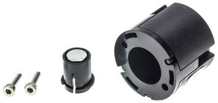
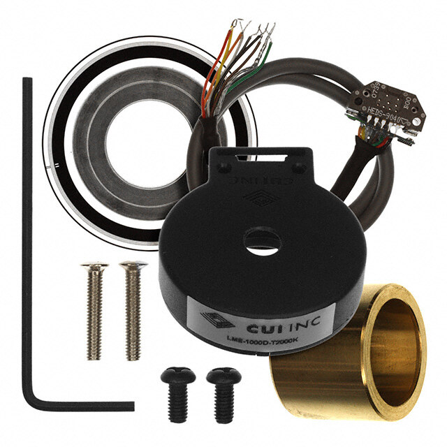
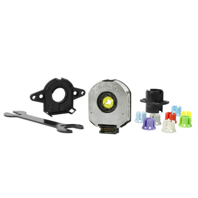
AEAT-6010/6012 Magnetic Encoder 10 or 12 bit Angular Detection Device Data Sheet Description Features Avago Technologies’ AEAT-60xx series of magnetic • 10 or 12 bits resolution encoders provides an integrated solution for angular • Contactless sensing technologies detection. With ease of use in mind, these magnetic • Wide temperature range from -40° to 125°C encoders are ideal for angular detection within 360°. Based on magnetic technologies, the device is non-con- • Absolute angular position detection tact and ensures reliable operations. It is able to provide • Synchronous serial interface (SSI) output for absolute absolute angle detection upon power-up, with a resolu- position data (binary format) tion of 0.0879°(12 bits version) or 0.35°(10bits version), • Code monotony error = ± 1 LSB which is equivalent to 4096 and 1024 positions per rev- olution respectively. The positional data is provided in • 5V supply serial bit stream. There is no upper speed limit; the only • Easy Assembly, No Signal Adjustment required restriction is that there will be fewer samples per revolu- • RoHS compliant tion as the speed increases. Exploded View Applications • Flow meter Magnetic Plastic • Angular detection Encoder Housing • Knob control • Rotary encoder Sensor PCB Assembly Magnet Plastic Snap Ring Hub Motor Plastic Base Plate 2 x screws Customer Note: “This product is not specifi cally designed or manufactured for use in any specifi c device. Customers are solely responsible for determining the suitability of this product for its intended application and solely liable for all loss, damage, expense or liability in connection with such use.”
Device Selection Guide [1] Part Number Resolution (bit) Operating Temperature (°C) Output Communication DC Supply Voltage (V), V DD AEAT-6012-A06 12 -40 to +125 Serial +5.0 AEAT-6010-A06 10 -40 to +125 Serial +5.0 Notes: 1. For other options of Magnetic Encoder, please refer to factory. Table 1. Absolute Maximum Ratings [2, 3] Parameter Symbol Limits Units Notes DC Supply Voltage at pin VDD = 5V VDD -0.3 to + 7 V Input Voltage Vi -0.3 to VDD+0.3 V Storage Temperature TSTG -40 to 125 °C Notes: 2. Stresses greater than those listed under Absolute Maximum Ratings may cause permanent damage to the device. This is stress rating only and functional operation of the device at these or any other conditions above those indicated in the operational sections of this specifi cation is not implied. 3. Exposure to absolute maximum rating conditions for extended periods may aff ect reliability. Table 2. Recommended Operating Condition Parameter Symbol Values Units Notes DC Supply Voltage at pin VDD = 5V VDD +4.5 / +5.5 V Ambient Temperature Tamb –40 to +125 °C Maximum Read-out Frequency fCLK ≤1 MHz >0 MHz Table 3. DC Characteristics DC Characteristics over Recommended Operating Range, typical at 25 °C Values Parameter Symbol Condition Min Typ. Max Units Notes VDD Supply Current IDD 16 20 mA Output High Voltage D0 VOH VDD-0.5 V Output Low Voltage D0 VOL VSS+0.4 V Output Current D0 IO 4 mA VDD pin = 4.5V Input High Voltage CLK, CSn VIH 0.7*VDD 4 Input Low Voltage CLK, CSn VIL 0.3*VDD Note: 4. CSn is internal pull-up. 2
Package Dimensions Base Plate Screw Mounting 8.5 ±1.0 C 0. 5 (cid:135)(cid:3)17 1 0 06-0. aft (cid:135) h S g n ti n ue Mobas 23mm 19mm Ø 23mm Figure 1. Package and recommended mounting dimension Parameters No. Parameter Value 1 Operating Temp(˚C) - 40 to +125 2 Shaft axial play (mm) ± 0.08 3 Shaft TIR (mm) 0.05 4 Mechanical speed (rpm) 12,000 5 Shaft diameter (mm) 6 + 0 / -0.01 6 Moment inertia (g-cm^2) 0.104 7 Shaft length – (mm) 8.5 ±1.0 8 Mounting screw size (mm) M2 x 0.4 x 8 (socket head cap screw, head Ø3.8 ± 0.18 mm) 9 Recommended screw torque 0.6 lb.inch 10 Encoder base plate thickness (mm) 2 11 Bolt circle ± 0.13 * Note:- For high temperature application, it is highly recommended that adhesive be applied at least to the screw and the base plate interface. Refer Application Note for further details. 3
Table 4. Timing Characteristics Timing Characteristics over Recommended Operating Range, typical at 25 °C Values Parameter Symbol Condition Min Typ. Max Units Notes Data output activated (logic high) TDO active 100 ns 1 First data shifted to output register tCLK FE 500 ns 2 Start of data output TCLK/2 500 ns 3 Data output valid TDO valid 375 ns 4 Data output tristate TDO tristate 100 ns 5 Pulse width of CSn TCSn 500 ns 6 Sampling rate for absolute output fabs 9.9 10.42 10.94 kHz 7 Power-up time tCF 8 10-bit version - - 50 ms 12-bit version - - 20 ms Notes: 1. Time between falling edge of CSn and data output activated 2. Time between falling edge of CSn and fi rst falling edge of CLK 3. Rising edge of CLK shifts out one bit a time 4. Time between rising edge of CLK and data output valid 5. After the last bit DO changes back to “tristate” 6. CSn=high; To initiate read-out of next angular position 7. Internal sampling rate. 8. Until internal compensation fi nished Timing Characteristics CS t CS tCLKFE TCLK/2 tCLKFE CLK 1 10 1 DO D9 D8 D7 D6 D5 D4 D3 D2 D1 D0 D9 t t t DO active DO valid DO Tristate Positional Data Bits Notes: 1. Please refer to Table 4 for Timing Characteristics. 2. For 12 bits version; the Positional Data Bits will start with D11 instead and end at D0. Figure 2. Timing Diagram for 10 bit Magnetic Encoder 4
Table 5. Linearity Parameter Symbol Min. Typ. Max Units Notes Integral Non-Linearity INL - ± 0.8 [1] ± 2.4 [2] Deg. Diff erential Non-Linearity 10-bit version DNL - - ± 0.176 Deg. No missing codes 12-bit version - - ± 0.044 Deg. No missing codes Notes: 1. Average value at typical operating and mounting conditions. 2. Maximum value over recommended operating range and over radial & axial mounting tolerances. Linearity Defi nitions Integral non-linearity Diff erential non-linearity Integral non-linearity (INL) is the maximum deviation Diff erential non-linearity (DNL) is the maximum deviation between actual angular position and the position of the step length from one position to the next. indicated by the encoder’s output count, over one revo- lution. It is defi ned as the most positive linearity error +INL or the most negative linearity error –INL from the best fi t line, whichever is larger. 1024 Most Negative Linearity Error nt -INL u o C ut utp 512 O er d o nc Most Positive Linearity Error E +INL Ideal Curve Actual Curve 0 0 90 180 270 360 Angular Position (Mechanical Degree) Figure 3. Integral non-linearity Table 6. Environmental Specifi cations Parameter Reference Standard Test Conditions Level Electromagnetic Compatibility (EMC) [1] Electrostatic discharge (ESD) immunity IEC/EN 61000-4-2 8kV Power frequency magnetic fi eld immunity IEC/EN 61000-4-8 30 A/m (continuous fi eld) 300 A/m (short duration fi eld) Level 4 Pulse magnetic fi eld immunity IEC/EN 61000-4-97 1000 A/m Level 5 Damped oscillatory magnetic fi eld immunity IEC/EN 61000-4-10 100 A/m Level 5 Mechanical Durability Vibration (Operating) IEC/EN 60068-2-6 10-500Hz at 5G Shock IEC/EN 60068-2-27 6ms at 200G Notes: 1. Suitable for applications in Industrial Environment Class 4. 5
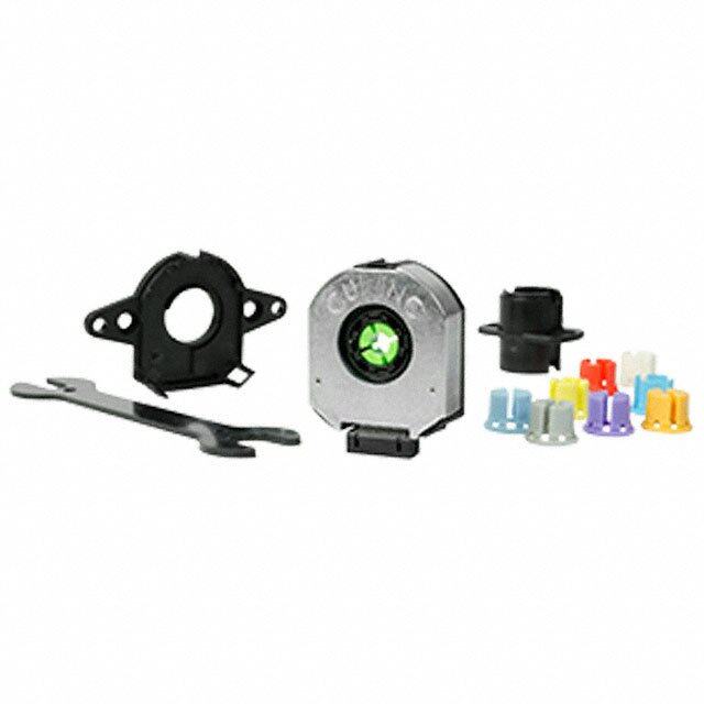
Electrical Connections VDD Vss DO Pin Symbol Description (cid:135) 22.6 1 VDD 5V Supply Voltage 2 CSn Chip Select – Input (See Figure 2) 3 VSS Supply Ground 4 CLK Serial Clock - Input (See Figure 2) CSn CLK 5 DO Serial Data - Output. (See Figure 2) 3.6 Figure 4. Electrical Connections 8.4 1.25 Figure 5. Basic connector dimensions Alignment Tool Set - Part number HEDS-8934 This optional alignment tool set consists of a gap setting plate and a centering jig. Refer to Application Note 5317 for the assembly guide. (cid:135)(cid:3)6.02 +0.01 11.0 0 (cid:135)(cid:3)11.98 0 -0.01 Centering Jig 0.50 ±0.01 R 3.02 0+0.1 R1 11.85 ±0.1 R1 Gap Setting Plate 5 31.5 Figure 6. Alignment tool set and recommended dimensions 6
Ordering Information A E A T - 6 0 1 - 0 - 5V 1 - Kit Encoder 0 - 10 bits A - Serial Output 06 - 6mm 2 - 12 bits For product information and a complete list of distributors, please go to our web site: www.avagotech.com Avago, Avago Technologies, and the A logo are trademarks of Avago Technologies in the United States and other countries. Data subject to change. Copyright © 2005-2011 Avago Technologies. All rights reserved. AV02-0188EN - August 12, 2011