ICGOO在线商城 > ADS8380EVM
- 型号: ADS8380EVM
- 制造商: Texas Instruments
- 库位|库存: xxxx|xxxx
- 要求:
| 数量阶梯 | 香港交货 | 国内含税 |
| +xxxx | $xxxx | ¥xxxx |
查看当月历史价格
查看今年历史价格
ADS8380EVM产品简介:
ICGOO电子元器件商城为您提供ADS8380EVM由Texas Instruments设计生产,在icgoo商城现货销售,并且可以通过原厂、代理商等渠道进行代购。 提供ADS8380EVM价格参考以及Texas InstrumentsADS8380EVM封装/规格参数等产品信息。 你可以下载ADS8380EVM参考资料、Datasheet数据手册功能说明书, 资料中有ADS8380EVM详细功能的应用电路图电压和使用方法及教程。
| 参数 | 数值 |
| ADC数 | 1 |
| 产品目录 | 编程器,开发系统半导体 |
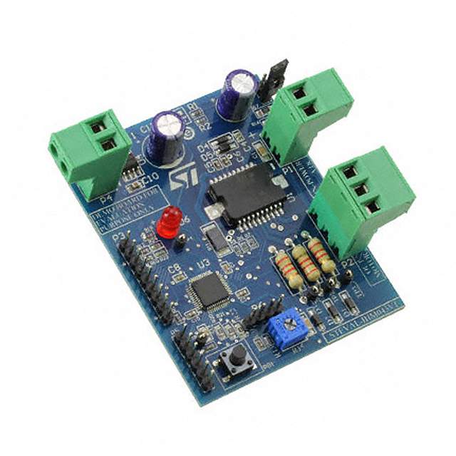
| 描述 | EVALUATION MODULE FOR ADS8380数据转换 IC 开发工具 ADS8380 Eval Mod |
| 产品分类 | 评估板 - 模数转换器 (ADC)工程技术开发工具 |
| 品牌 | Texas Instruments |
| 产品手册 | http://www.ti.com/lit/pdf/slau146 |
| 产品图片 |
|
| rohs | 否无铅 / 符合限制有害物质指令(RoHS)规范要求 |
| 产品系列 | 数据转换 IC 开发工具,Texas Instruments ADS8380EVM- |
| 数据手册 | 点击此处下载产品Datasheethttp://www.ti.com/lit/pdf/slau146 |
| 产品型号 | ADS8380EVM |
| 不同条件下的功率(典型值) | 115mW @ 600kSPS |
| 产品 | Evaluation Boards |
| 产品培训模块 | http://www.digikey.cn/PTM/IndividualPTM.page?site=cn&lang=zhs&ptm=13240 |
| 产品目录页面 | |
| 产品种类 | Development & Evaluation Tools (Kits, Modules, and Boards) |
| 位数 | 18 |
| 使用的IC/零件 | ADS8380 |
| 其它名称 | 296-18380 |
| 制造商产品页 | http://www.ti.com/general/docs/suppproductinfo.tsp?distId=10&orderablePartNumber=ADS8380EVM |
| 商标 | Texas Instruments |
| 工作温度 | -40°C ~ 85°C |
| 工作电源电压 | 3.3 V to 5 V |
| 工具用于评估 | ADS8380 |
| 工厂包装数量 | 1 |
| 所含物品 | 板 |
| 接口类型 | SMA |
| 数据接口 | 串行 |
| 标准包装 | 1 |
| 相关产品 | /product-detail/zh/ADS8380IRHPT/296-17634-6-ND/1944966/product-detail/zh/ADS8380IBRHPT/296-17633-6-ND/1944965/product-detail/zh/ADS8380IRHPRG4/ADS8380IRHPRG4-ND/1689752/product-detail/zh/ADS8380IRHPR/ADS8380IRHPR-ND/1689751/product-detail/zh/ADS8380IBRHPTG4/ADS8380IBRHPTG4-ND/1689750/product-detail/zh/ADS8380IBRHPRG4/ADS8380IBRHPRG4-ND/1689749/product-detail/zh/ADS8380IBRHPR/ADS8380IBRHPR-ND/1689748/product-detail/zh/ADS8380IRHPT/296-17634-1-ND/716495/product-detail/zh/ADS8380IBRHPT/296-17633-1-ND/716494/product-detail/zh/ADS8380IRHPT/296-17634-2-ND/716417/product-detail/zh/ADS8380IBRHPT/296-17633-2-ND/716416 |
| 类型 | ADC |
| 输入范围 | 0 ~ 4.2 V |
| 采样率(每秒) | 600k |





- 商务部:美国ITC正式对集成电路等产品启动337调查
- 曝三星4nm工艺存在良率问题 高通将骁龙8 Gen1或转产台积电
- 太阳诱电将投资9.5亿元在常州建新厂生产MLCC 预计2023年完工
- 英特尔发布欧洲新工厂建设计划 深化IDM 2.0 战略
- 台积电先进制程称霸业界 有大客户加持明年业绩稳了
- 达到5530亿美元!SIA预计今年全球半导体销售额将创下新高
- 英特尔拟将自动驾驶子公司Mobileye上市 估值或超500亿美元
- 三星加码芯片和SET,合并消费电子和移动部门,撤换高东真等 CEO
- 三星电子宣布重大人事变动 还合并消费电子和移动部门
- 海关总署:前11个月进口集成电路产品价值2.52万亿元 增长14.8%

PDF Datasheet 数据手册内容提取
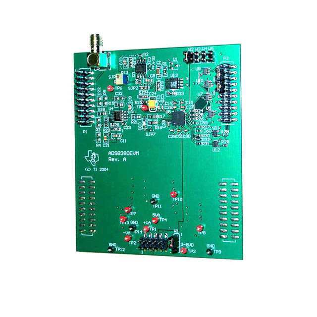
User's Guide SLAU146–December2004 ADS8380EVM This user's guide describes the characteristics, operation, and use of the ADS8380 18-bit, 600-kHz, high-speed, serial interface analog-to-digital converter evaluation board (EVM). A complete circuit description, schematic diagram, and bill of materials areincluded. ThefollowingrelateddocumentsareavailableontheTIWebsiteatwww.ti.com. DataSheets: LiteratureNumbers: ADS8380 SLAS387 REF1004C-2.5 SBVS002 SN74AHC1G125 SCLS377 THS4031 SLOS224 OPA132 SBOS054 Contents 1 EVMOverview............................................................................................................... 2 2 AnalogInterface.............................................................................................................. 2 3 DigitalInterface .............................................................................................................. 4 4 PowerSupplies .............................................................................................................. 5 5 UsingtheEVM............................................................................................................... 6 6 ADS8380EVMBillOfMaterials............................................................................................ 7 8 BoardLayers................................................................................................................. 9 9 Schematics.................................................................................................................. 13 ListofFigures 1 InputBufferCircuit........................................................................................................... 3 2 TopLayer..................................................................................................................... 9 3 PowerPlane................................................................................................................ 10 4 GroundPlane............................................................................................................... 11 5 BottomLayer................................................................................................................ 12 ListofTables 1 AnalogInputConnector..................................................................................................... 2 2 JumperSetting............................................................................................................... 4 3 PinoutforSerialControlConnectorP2................................................................................... 5 4 PowerSupplyTestPoints.................................................................................................. 5 5 PowerConnectorJ2Pinout................................................................................................ 5 7 ADS8380EVMBillofMaterials............................................................................................. 7 SLAU146–December2004 ADS8380EVM 1
www.ti.com EVMOverview 1 EVM Overview 1.1 Features • Full-featuredevaluationboardfortheADS838018-bit,600-kHz,single-channel,high-speed serial-interfaceanalog-to-digitalconverter(ADC) • Onboardsignalconditioning • Onboardreference • Inputandoutputdigitalbuffer 2 Analog Interface TheADS8380analog-to-digitalconverterhasbothapositiveandnegativeanaloginputpin.Asignalfor thepositiveinputpincanbeappliedatconnectorP1,pin2(showninTable1)orappliedtothecenterpin ofSMAconnectorJ1.TheEVMshipswiththenegativeinputpinshortedtogroundclosetotheconverter usingviaSJP7.Thenegativeandpositiveinputpinshavearangeof-200mVto+200mVand-200mV toVREF+200mV,respectively. Table1.AnalogInputConnector Description SignalName ConnectorPinNo. SignalName Description InvertingInput –IN P1.1 P1.2 +IN NoninvertingInput Reserved N/A P1.3 P1.4 N/A Reserved Reserved N/A P1.5 P1.6 N/A Reserved Reserved N/A P1.7 P1.8 N/A Reserved Ground AGND P1.9 P1.10 N/A Reserved Ground AGND P1.11 P1.12 N/A Reserved Reserved N/A P1.13 P1.14 N/A Reserved Ground AGND P1.15 P1.16 N/A Reserved Ground AGND P1.17 P1.18 N/A Reserved Reserved N/A P1.19 P1.20 REF+ ExternalReferenceInput 2.1 Signal Conditioning ItisarecommendedpracticetobuffertheanaloginputtoanySAR-typeconverterwithahigh-speed, fast-settling,low-noiseamplifier.TheamplifiercircuitshowninFigure1isthebuffercircuitusedonthe ADS8380EVM.ThiscircuitconsistsoftheTHS4031,ahigh-speed,low-noise,low-distortionamplifier configuredasaninvertinggainofone.ThecircuitshowninFigure1wasoptimizedtoachievetheac specifications(i.e.,SNR,THD,SFDR,etc.)listedintheADS8380datasheet.The12-W seriesresistor workswiththecapacitortofiltertheinputsignal,butalsoisolatestheamplifierfromthecapacitiveload. The6800-pFcapacitortogroundattheinputoftheADCworkswiththeseriesresistortofiltertheinput signal,behaveslikeachargereservoir,andprovidesashorttogroundforhigh-frequencynoiseand kickbackcurrentswhenthedeviceswitchesfromholdtosamplemode.Thisexternalfiltercapacitoralso workswiththeamplifiertochargetheinternalsamplingcapacitorduringsamplingmode. Thetypeofinputcapacitorsusedinthesignalpathcanmakeafewdecibelsofdifferenceinac performance.PolypropyleneorC0G-typecapacitorsarerecommendedfortheinputsignalpath. Polypropylenecapacitorscausetheleastdistortionoftheinputsignalandhaveexcellentlong-term stability,butareexpensiveandbulky.C0Gceramiccapacitorscostless,comeinsmallerpackages,and performaswellaspolypropylenecapacitorsinmanyapplications,butarenotasstableovertimeand temperature.The68-pFand6800-pFcapacitorsinstalledontheEVMarelow-costC0Gtype, manufacturedbyTDKCorporation. 2 ADS8380EVM SLAU146–December2004
www.ti.com AnalogInterface 604 (cid:1) VIN 604 (cid:1) −VCC 0.1 (cid:2)F 1 (cid:2)F 4.096 V _ 12 (cid:1) 100 (cid:1) THS4031 IN+ 10 k(cid:1) + 1 (cid:2)F 6800 pF 1 (cid:2)F 0.1 (cid:2)F IN− +VCC Figure1.InputBufferCircuit 2.2 Reference Voltage TheADS8380EVMallowsthedesignertoselectinternal,onboard,oruser-suppliedreference-voltage sources.Theinternalreferenceisa4.096-VreferencevoltagegeneratedbytheADS8380onpin9.The onboardreferencecanbeeitheraREF3040(U1)orREF1004-2.5(U13).TheEVMshipswiththe REF1004-2.5installed.Thereferenceamplifier,U3,issetforagainof1.6,enablingittotakea2.5-V inputandoutput4.1Vforusewiththeconverter,oraspartofthedcoffsetvoltagecircuitfortheinput buffer(U4).Theuser-suppliedreferencevoltageisappliedtoconnectorP1,pin20andcanberouted throughthereferencebufferandfiltered,ifdesired.TheEVMallowsanumberofconfigurations.See Table1forjumpersettingsorthefullschematicinSection9formoreinformation.ThecommonSOIC footprintofU13allowsuserstoevaluatethisconverterwithvariousreferenceICs. TheADS8380EVMshipswiththeinternalreferencetieddirectlytothereferencepinoftheconverter. SLAU146–December2004 ADS8380EVM 3
www.ti.com DigitalInterface Table2.JumperSetting Reference Pins/Pads Designator Description 1-2 2-3 SJP1 Bufferonboardreference(REF1004-2.5) Shorted(1) Open Bufferuser-suppliedreferencevoltageappliedatP1pin20 Open Shorted SJP2 ConnectexternalreferencedirectlytoSJP4 Shorted(1) Open ConnectbufferedexternalreferencetoSJP4 Open Shorted SJP3 ConnectU2negativesupplytoground Shorted Open ConnectU2negativesupplyto–VCC Open Shorted(1) SJP4 ConnectinternalreferencetoREFIN Shorted(1) Open ConnectexternalreferencetoREFIN Open Shorted SJP5 ConnectU4negativesupplytoground Shorted Open ConnectU4negativesupplyto–VCC Open Shorted(1) SJP6 ConnectDCoffsetvoltagetoU4 Shorted(1) N/A SJP7 Connect-INpintoanalogground Shorted(1) N/A W1 Connect+5VDtoBVDD Shorted(1) Open Connect+3.3VDtoBVDD Open Shorted W2 Setsignalstraightbinary/2scomplement(SB/2C)high Shorted N/A W3 Setpowerdownsignal(PD)high Shorted N/A W4 Setframesyncsignal(FS)high Shorted N/A W5 Setchipselectsignal(CS)low Shorted N/A (1) FactoryInstalled 3 Digital Interface TheADS8380EVMisdesignedforeasyinterfacingtomultipleplatforms.Samtecplugandsocket connectorsprovideaconvenientdualrowheader/socketcombinationatP1andP2toplugintoprototype boardsorthroughribboncabletousersystemboards. ThedigitalinputandoutputsignalsfortheconverterisavailableatconnectorP2ontheADS8380EVM; seeTable3fortheconnectorpinout. 4 ADS8380EVM SLAU146–December2004
www.ti.com PowerSupplies Table3.PinoutforSerialControlConnectorP2 Description SignalName ConnectorPin SignalName Description ChipSelect CS P2.1 P2.2 SB/2C Straightbinaryor2scomplementoutput SerialClock SCLK P2.3 P2.4 DGND Ground Reserved N/A P2.5 P2.6 N/A Reserved FrameSync FS P2.7 P2.8 N/A Reserved Reserved N/A P2.9 P2.10 N/A Reserved Reserved N/A P2.11 P2.12 N/A Reserved SerialDataOut SDO P2.13 P2.14 N/A Reserved BUSY BUSY P2.15 P2.16 N/A Reserved ConvertStart CONVST P2.17 P2.18 DGND Ground Powerdown PD P2.19 P2.20 N/A Reserved 4 Power Supplies TheEVMacceptsfourpowersupplies: • Adual– Vsdcsupplyforthedual-supplyoperationalamplifiers.Themaximumrecommendedvoltage is– 12Vdc. • Asingle+5-Vdcsupplyfortheanalogsectionoftheboard(A/D+Reference). • Asingle+5-Vdcor+3.3-Vdcsupplyforthedigitalsectionoftheboard(A/D+buffers). Therearetwowaystoprovidethesevoltages.Thefirstwayistoconnectthevoltagestothetestpoints listedinTable4. Table4.PowerSupplyTestPoints TestPoint Signal Description TP1 +VA Connect+12-Vdcsupplyforamplifier TP2 –VA Connect–12-Vdcsupplyforamplifier TP3 +BVDD Apply+3.3Vdcor+5Vdc.SeeADCdatasheetforfullrange. TP4 +AVCC Apply+5Vdc ThesecondwayistousethepowerconnectorJ2andderivethevoltageselsewhere.Table5givesthe pinoutforJ2.Ifusingthisconnector,setW1jumpertoconnect+3.3VDor+5VDfromJ2to+BVDD.Shunt pins1-2toselect+5VD,orpins2-3toselect+3.3VDasthesourceforthedigitalbuffervoltagesupply (+BVDD). Table5.PowerConnectorJ2Pinout Signal J2Pin Signal +VA(+12V) 1 2 –VA(–12V) +5VA 3 4 N/C DGND 5 6 AGND N/C 7 8 N/C +3.3VD 9 10 +5VD SLAU146–December2004 ADS8380EVM 5
www.ti.com UsingtheEVM 5 Using the EVM TheADS8380EVMservesthreefunctions: 1. Asareferencedesign 2. Asaprototypeboard 3. Asasoftwaretestplatform 5.1 Reference Design Asareferencedesign,theADS8380EVMcontainstheessentialcircuitrytoshowcasetheanalog-to-digital converter.Thisessentialcircuitryincludestheinputamplifier,referencecircuit,andbuffers.TheEVM analog-inputcircuitisoptimizedfora100-kHzinputsignal;therefore,usersmayneedtoadjustthe resistorandcapacitorvaluestoaccommodatehigherfrequencies.Inac-typeapplicationswheresignal distortionisaconcern,polypropyleneorC0G-typecapacitorsarerecommendedforuseinthesignalpath. 5.2 Prototype Board Asaprototypeboard,thebuffercircuithasresistorpadsforconfiguringtheinputaseithersingle-endedor fullydifferentialinput.Theinputcircuitcanbemodifiedtoaccommodateuserprototypeneeds,whetherit beevaluatinganotherdifferentialamplifierorlimitingnoiseforbestperformance.Theanalog,power,and digitalconnectorscanbemadetoplugintoastandard0.1-in.breadboardorribboncablestointerface directlytoFPGAsorprocessors. 5.3 Software Test Platform Asasoftwaretestplatform,connectorsP1andP2plugintotheserialinterfaceconnectorsofthe5-6K InterfaceBoard.The5-6KInterfaceBoardplugsintotheTMS320C5000andTMS320C6000DigitalSignal Processorstarterkits(DSK).Seethe5-6KInterfaceBoardUser’sGuide(SLAU104)formoreinformation. 6 ADS8380EVM SLAU146–December2004
www.ti.com ADS8380EVMBillOfMaterials 6 ADS8380EVM Bill Of Materials ThefollowingtablecontainsacompletebillofmaterialsfortheADS8380EVM.Theschematicdiagramis alsoprovidedforreference.ContacttheProductInformationCenteroremaildataconvapps@list.ti.comfor questionsregardingthisEVM. Table7.ADS8380EVMBillofMaterials Item Reference Manufacturer's QTY Value Footprint Manufacturer Description No. Designator PartNumber 1 1 49.9W R1 805 Panasonic-ECGor ERJ-6ENF49R9V RES49.9W 1/10W1%0805SMD Alternate 2 1 1.2kW R2 603 YageoAmericaor 9C06031A1201FKHFT RES1.20kW 1/10W1%0603SMD Alternate 3 2 NI R4,R5 805 NotInstalled NotInstalled 4 3 0W R6,R15,R30 603 Panasonic-ECGorAlter- ERJ-3GEY0R00V RES0W 1/16W5%0603SMD nate 5 7 10kW R7,R8,R9, 603 Panasonic-ECGor ERJ-3EKF1002V RES10KW 1/16W1%0603SMD R10,R11, Alternate R12,R32 6 1 10kW R13 BOURNS Bourns 3214W-1-103E TRIMPOT10KW 4MMTOPADJSMD _32X4W 7 1 768W R14 603 Panasonic-ECGor ERJ-3EKF7680V RES768W 1/16W1%0603SMD Alternate 8 2 0W R16,R17 805 Panasonic-ECGor ERJ-6GEY0R00V RES0W 1/10W5%0805SMD Alternate 9 2 604W R18,R19 805 Panasonic-ECGor ERJ-6ENF6040V RES604W 1/10W1%0805SMD Alternate 10 1 100W R20 805 Panasonic-ECGor ERJ-6ENF1000V RES100W 1/10W1%0805SMD Alternate 11 1 12W R21 805 Panasonic-ECGor ERJ-6GEYJ120V RES12W 1/8W5%0805SMD Alternate 12 8 100 R22,R23, 603 Panasonic-ECGor ERJ-3EKF1000V RES100W 1/16W1%0603SMD R24,R25, Alternate R26,R27, R28,R29 13 1 1kW R31 603 Panasonic-ECGor ERJ-3EKF1001V RES1kW 1/16W1%0603SMD Alternate 14 1 49.9kW R33 805 Panasonic-ECGor ERJ-6ENF4992V RES49.9kW 1/10W1%0805SMD Alternate 15 1 47µF C1 1206 TDKCorporationor C3216X5R0J476M CAPCER47µF6.3VX5R20%1206 Alternate 16 5 1µF C2,C3,C4, 805 TDKCorporationor C2012X7R1E105K CAPCER1µF25VX7R0805T/R C5,C31 Alternate 17 8 NI C6,C7,C21, 603 NotInstalled NotInstalled MultilayerCeramic C23,C44, C45,C59,C60 18 4 0.1µF C8,C9,C10, 805 TDKCorporationor C2012X7R1E104K CAPCER0.1µF25VX7R10%0805 C11 Alternate 19 12 0.1µF C12,C13, 603 TDKCorporationor C1608X7R1E104K CAPCER0.1µF25VX7R10%0603 C16,C17, Alternate C18,C52, C53,C54, C55,C56, C57,C58 20 6 2.2µF C14,C15, 603 TDKCorporationor C1608X5R1A225MT CAPCER2.2µF6.3VX5R20%0603 C19,C20, Alternate C28,C50 21 3 NI C22,C32,R3 805 NotInstalled NotInstalled MultilayerCeramic 22 1 10µF C24 3528 KemetorAlternate T491B106K016AS CAPACITORTANT10µF16V10%SMD 23 8 0.01µF C25,C26, 603 TDKCorporationor C1608X7R1H103KT CAPCER10000pF50VX7R10%0603 C27,C29, Alternate C30,C42, C43,C51 24 1 6800µF C33 805 TDKCorporationor C2012C0G1H682J CAPCER6800pF50VC0G5%0805 Alternate 25 4 10µF C34,C35, 1206 TDKCorporationor C3216X5R1C106KT CAPCER10µF16VX5R20%1206 C36,C37 Alternate 26 4 10µF C38,C39, 6032 Pansonic-ECGor ECS-T1EC106R CAP10µF25VTantalumTESMD C40,C41 Alternate 27 5 1000pF C46,C47, 603 TDKCorporationor C1608C0G1H102KT CAPCER1000pF50VC0G0603T/R C48,C49,C62 Alternate SLAU146–December2004 ADS8380EVM 7
www.ti.com ADS8380EVMBillOfMaterials Table7.ADS8380EVMBillofMaterials (continued) Item Reference Manufacturer's QTY Value Footprint Manufacturer Description No. Designator PartNumber 28 1 1µF C61 603 TDKCorporationor C1608X5R1A105KT CAPCER1µF10VX5R10%0603 Alternate 29 4 MMZ2 L1,L2,L3,L4 805 TDKCorporationor MMZ2012R601A FERRITECHIP600W 500mA0805 012R6 01A 30 1 NI U1 3-SOT-23 NotInstalled NotInstalled REF3040SOT23-3CMOSVoltageRefer- ence 31 1 OPA132 U2 8-SOP(D) TexasInstruments OPA132U High-SpeedFET-InputOperationalAmplifier 32 8 SN74X1G125 U3,U6,U7, 5-SOT(DBV) TexasInstruments SN74AHC1G125DBVR SingleBusBufferGate/LineDriverwith U8,U9,U10, 3-StateOutput U11,U12 33 1 THS4031 U4 8-SOT(D) TexasInstruments THS4031CD 100-MHzLow-NoiseHigh-SpeedAmplifier 34 1 ADS8380 U5 28-PQFP TexasInstruments ADS8380IBRHPT 18-Bit600kSPSSerialAnalog-to-Digital (QFN) Converter 35 1 REF1004-2.5 U13 8-SOP(D) TexasInstruments REF1004C-2.5 2.5-VMicropowerVoltageReference 36 1 SMA_PCB_ J1 SMA_JACK JohnsonComponentsInc. 142-0701-301 RightAngleSMAConnector MT 37 1 PowerSupply J2 5X2X.1_ Samtec SSW-105-22-S-D 0.025-In.SMTSocket-BottomSideofPWB SMT_Socket -VS 38 1 Samtec TSM-105-01-T-D-V 0.025-In.SMTPlug-TopSideofPWB -P 39 2 10X2X.1 P1,P2 10X2X.1 Samtec SSW-110-22-S-D-VS 0.025-In.SMTSocket-BottomSideofPWB _SMT_P LUG_&_ SOCKET 40 2 Samtec TSM-110-01-T-D-V-P 0.025-In.SMTPlug-TopSideofPWB 41 1 3POS_ W1 3pos_jump Samtec TSW-103-07-L-S 3-PositionJumper_0.1-In.Spacing JUMPER 42 4 2POS_ W2,W3,W4, 2pos_jump Samtec TSW-102-07-L-S 2-PositionJumper_0.1-In.Spacing JUMPER W5 43 2 SJP2 SJP6,SJP7 SJP2 NotInstalled NotInstalled Pad2PositionJumper 44 5 SJP3 SJP1,SJP2, SJP3 NotInstalled NotInstalled Pad3PositionJumper SJP3,SJP4, SJP5 45 10 TP_.025 TP1,TP2, test_point2 KeystoneElectronics 5000K-ND TestPointPCMini0.040-In.DRed TP3,TP4, TP5,TP6, TP7,TP8, TP10,TP13, 46 4 TP_0.25 TP9,TP11, test_point2 KeystoneElectronics 5001K-ND TestPointPCMini0.040-InDBlack TP12,TP14 8 ADS8380EVM SLAU146–December2004
www.ti.com BoardLayers 8 Board Layers Figure2.TopLayer SLAU146–December2004 ADS8380EVM 9
www.ti.com BoardLayers Figure3.PowerPlane 10 ADS8380EVM SLAU146–December2004
www.ti.com BoardLayers Figure4.GroundPlane SLAU146–December2004 ADS8380EVM 11
www.ti.com BoardLayers Figure5.BottomLayer 12 ADS8380EVM SLAU146–December2004
www.ti.com Schematics 9 Schematics Schematicdiagramsareappendedfollowingthispage. SLAU146–December2004 ADS8380EVM 13
1 2 3 4 5 6 Revision History REV ECN Number Approved D D J1 P1 1 2 +IN 3 4 5 6 7 8 9 10 11 12 13 14 15 16 17 18 19 20 EXT_REF Analog Input SB/2C P2 CS CS SCLK 1 2 SCLK 3 4 C TP1 FS FS 57 68 C 9 10 +VA B_SDO 11 12 +VA B_SDO B_BUSY 13 14 B_BUSY CONVST 15 16 TP2 CONVST PD 17 18 J2 PD 19 20 ++AVVACC 1 2 -VA -VA -VA Serial Control DGND 3 4 AGND 5 6 +3.3VD 7 8 +5VD 9 10 Power Supply TP3 W1 +BVDD +BVDD +AVCC +AVCC TP4 Circuits B B ti A A 12500 TI Boulevard. Dallas, Texas 75243 TITLE: ADS8370EVM/ADS8380EVM Engineer: Lijoy Philipose DOCUMENT CONTROL #: REV: Drawn By: Lijoy Philipose 6458769 A FILE: BlockDiagram.sch DATE: 30-Jun-2005 SIZE: SHEET: 1 OF: 2 1 2 3 4 5 6
1 2 3 4 5 6 +VBD Revision History C16 REV ECN Number Approved U3 D +5VCC R1 12 UNION1IUT GND 3 SJP11 2 +VCC C1u2F C0.81uF SJP2 1 2 B0_.S1BuF/2CC52B0_.P1DuF +45VBD45SYVNCC74YVXCGC1NOGDAE1G2NO5DAE 123U6123 W2 W+V3BD W4 R101k1 R101k2 D 49.9 C471uF E+X5TV_CRCEF 3 R1.22k 32 742 51 OPA613U22 R06 3 +5VCC C14 C2.125uF +5VCC CBC_5BF3_5SC4S0.01.u1+FuV+FBV45DB45DSNSYVNCYV74CC7X4CX1GG1GNOG1NDOAE21DAE52U5U78123123 CSFPSCSCBDSOL/N2KCVST R7 R8 R9 R10 W5 CSSOBCPCFN/DSSL2VKCST +5VCC 1 NUC13 NC 8R493.39k 1 SJP3 3 C1u4F -VC0C.110CuF 2C0..2206u1FuF C0.2071uF BC_C5OC5N5V06.S1Tu+FVB+DV45BDSNS7N4YVXC74C1XG11GG2NO51DAE25U9123 10k 10k 10k 10k C1u6F1 C106020pF 234 +EGVNNIDN VRNNECCF 567 CN2I1 SJP4 3 2 R15 R10202 B_SCL0K.1uF 45 SNYVC74CX1GGNO1DAE25U10123 C REF1004-2.5 R13 R14 1 0 C17 C25 100100100100100 C 3 10k 1 768 TP5 + C102u4F 0.1uF 0.01uF 7654321 RN3I TP2126 SJP6 R10200 C1u3F C0.91uF3 +VC7C81 T6UH4S4031 R21* R17 +5VCC 111110123489 RRNIINVNNAEECC+-FFAIONUDREFMAGNDTS8VAVAU375AGNDVA0/AAGNDAGNDD+VAAGNDS8AGNDBVDD38CSB/2CBGND0OBNSSUCVDSCPSLFOYDKSST 22222222345678 R23SBR24DUOSR25YR26R27 RR330CC15690 NNII 01k +VBR1D03k2 123 USUNOAG11127EN4DX1VGC1YC25 45++VVBBDDR10208C0C.55178uF B_SDO RN4I C1u3F1 2 4 5C23* 12 0 0.C1u1F8 2.2uCF28 15161718192021 123 OAGEND VCYC 45 R102009.1uF B_BUSY +IN C33* SN74X1G125 1 2 N3I 6800pF C29 C19 0.C013u0F 2.C2u2F0 B R60148 SJP5 C5 -VCC11C 2 R016 +5VCC 0.01uF +5VCC2.2uF +VBD B 1uF 0.1uF R5 C22 NI SJP7 NI C51 C50 1 0.01uF 2.2uF R19 604 C32* NI TP7 L3 +VCC L2 TP10 +5VCC +VA MMZ2012R601A +AVCC MMZ2012R601A + C41 C6 C44 C48 C103u5F +C103u9F C0.113uF 0.C0413uF C1n4F7 C103u6F TP12 10uF NI NI 1000pFTP14 ti TP11 A +BVDD MMLZ12012R601A TP8 +VBD C103u7F +C104u0F CN7I CN4I5 C104090pF A C103u4F + C103u8F C0.112uF 0.C0412uF C1n4F6 L4 TP13 TITLE: 12C5ir0c0ui tTsI Boulevard. Dallas, Texas 75243 -VA MMZ2012R601A -VCC DEnragwinne eBry:: LLiijjooyy PPhhiilliippoossee DOCUMENT CONTROL #:6458769 RAEV: TP9 FILE: Circuits DATE: 30-Jun-2005 SIZE: SHEET: 2 OF: 2 1 2 3 4 5 6
IMPORTANT NOTICE Texas Instruments Incorporated and its subsidiaries (TI) reserve the right to make corrections, modifications, enhancements, improvements, and other changes to its products and services at any time and to discontinue any product or service without notice. Customers should obtain the latest relevant information before placing orders and should verify that such information is current and complete. All products are sold subject to TI’s terms and conditions of sale supplied at the time of order acknowledgment. TI warrants performance of its hardware products to the specifications applicable at the time of sale in accordance with TI’s standard warranty. Testing and other quality control techniques are used to the extent TI deems necessary to support this warranty. Except where mandated by government requirements, testing of all parameters of each product is not necessarily performed. TI assumes no liability for applications assistance or customer product design. Customers are responsible for their products and applications using TI components. To minimize the risks associated with customer products and applications, customers should provide adequate design and operating safeguards. TI does not warrant or represent that any license, either express or implied, is granted under any TI patent right, copyright, mask work right, or other TI intellectual property right relating to any combination, machine, or process in which TI products or services are used. Information published by TI regarding third-party products or services does not constitute a license from TI to use such products or services or a warranty or endorsement thereof. Use of such information may require a license from a third party under the patents or other intellectual property of the third party, or a license from TI under the patents or other intellectual property of TI. Reproduction of information in TI data books or data sheets is permissible only if reproduction is without alteration and is accompanied by all associated warranties, conditions, limitations, and notices. Reproduction of this information with alteration is an unfair and deceptive business practice. TI is not responsible or liable for such altered documentation. Resale of TI products or services with statements different from or beyond the parameters stated by TI for that product or service voids all express and any implied warranties for the associated TI product or service and is an unfair and deceptive business practice. TI is not responsible or liable for any such statements. Following are URLs where you can obtain information on other Texas Instruments products and application solutions: Products Applications Amplifiers amplifier.ti.com Audio www.ti.com/audio Data Converters dataconverter.ti.com Automotive www.ti.com/automotive DSP dsp.ti.com Broadband www.ti.com/broadband Interface interface.ti.com Digital Control www.ti.com/digitalcontrol Logic logic.ti.com Military www.ti.com/military Power Mgmt power.ti.com Optical Networking www.ti.com/opticalnetwork Microcontrollers microcontroller.ti.com Security www.ti.com/security Telephony www.ti.com/telephony Video & Imaging www.ti.com/video Wireless www.ti.com/wireless Mailing Address: Texas Instruments Post Office Box 655303 Dallas, Texas 75265 Copyright 2004, Texas Instruments Incorporated
 Datasheet下载

