ICGOO在线商城 > 开发板,套件,编程器 > 评估板 - 模数转换器(ADC) > ADS5404EVM
- 型号: ADS5404EVM
- 制造商: Texas Instruments
- 库位|库存: xxxx|xxxx
- 要求:
| 数量阶梯 | 香港交货 | 国内含税 |
| +xxxx | $xxxx | ¥xxxx |
查看当月历史价格
查看今年历史价格
ADS5404EVM产品简介:
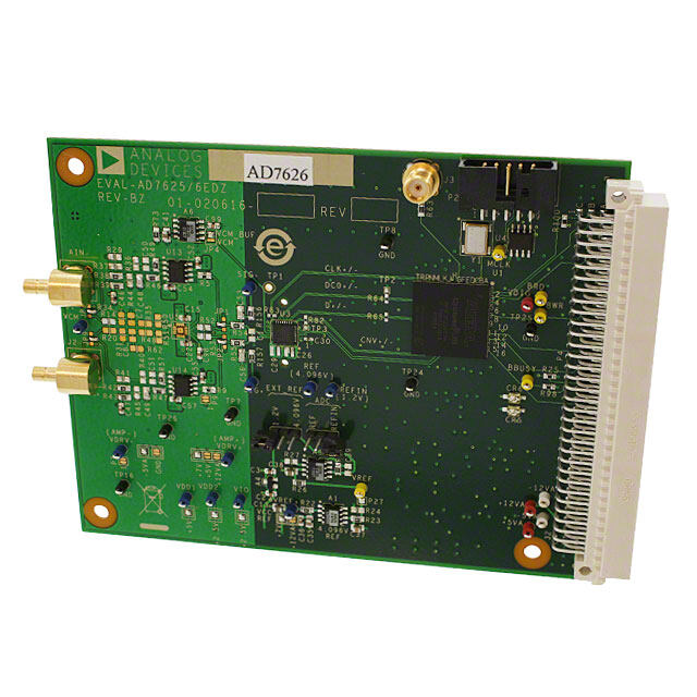
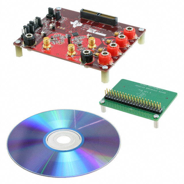
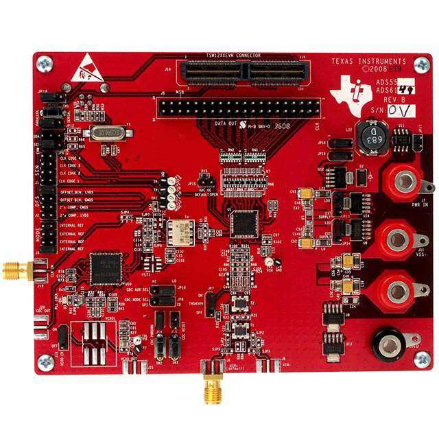
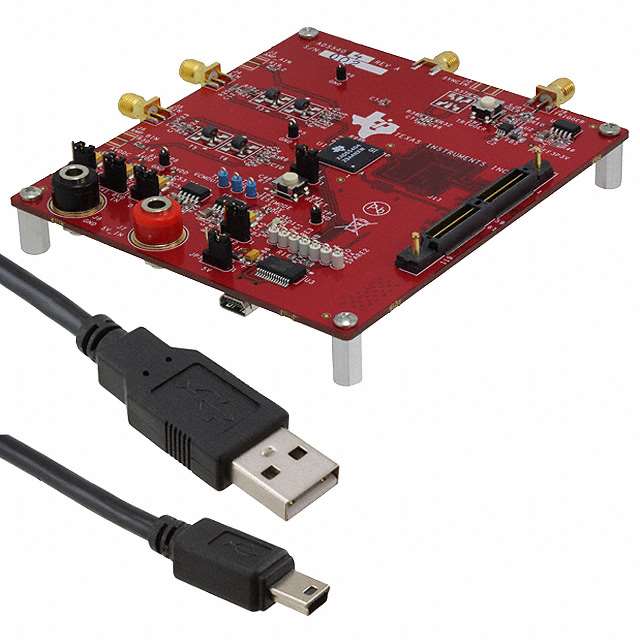
ICGOO电子元器件商城为您提供ADS5404EVM由Texas Instruments设计生产,在icgoo商城现货销售,并且可以通过原厂、代理商等渠道进行代购。 ADS5404EVM价格参考¥3773.05-¥3773.05。Texas InstrumentsADS5404EVM封装/规格:评估板 - 模数转换器(ADC), ADS5404 - 12 Bit 500M Samples per Second Analog to Digital Converter (ADC) Evaluation Board。您可以下载ADS5404EVM参考资料、Datasheet数据手册功能说明书,资料中有ADS5404EVM 详细功能的应用电路图电压和使用方法及教程。
| 参数 | 数值 |
| ADC数 | 2 |
| 产品目录 | 编程器,开发系统嵌入式解决方案 |
| 描述 | ADS5404EVM EVALUATION MODULE数据转换 IC 开发工具 ADS5404 EVAL MOD |
| 产品分类 | 评估板 - 模数转换器 (ADC)工程工具 |
| 品牌 | Texas Instruments |
| 产品手册 | http://www.ti.com/litv/pdf/slau450 |
| 产品图片 |
|
| rohs | 符合RoHS含铅 / 不符合限制有害物质指令(RoHS)规范要求 |
| 产品系列 | 模拟与数字IC开发工具,数据转换 IC 开发工具,Texas Instruments ADS5404EVM- |
| mouser_ship_limit | 根据美国政府的出口法规规定,Mouser无法将此产品销售到您所在的国家。 |
| 数据手册 | http://www.ti.com/lit/pdf/slau450点击此处下载产品Datasheet |
| 产品型号 | ADS5404EVM |
| 不同条件下的功率(典型值) | 1.84W @ 500MSPS |
| 产品 | Evaluation Modules |
| 产品种类 | 数据转换 IC 开发工具 |
| 位数 | 12 |
| 使用的IC/零件 | ADS5404 |
| 其它名称 | 296-36188 |
| 商标 | Texas Instruments |
| 工作温度 | -40°C ~ 85°C |
| 工作电源电压 | 5 V |
| 工具用于评估 | ADS540x, ADS54T0x |
| 所含物品 | 板 |
| 接口类型 | SPI, USB |
| 描述/功能 | Provides a platform for evaluating a two-channel, 12-bit ADC operating at sampling rates of up to 800 MSPS |
| 数据接口 | DDR LVDS |
| 标准包装 | 1 |
| 用于 | ADS540x, ADS54T0x |
| 类型 | ADC |
| 系列 | ADS5404 |
| 输入范围 | 1 Vpp |
| 采样率(每秒) | 500M |



- 商务部:美国ITC正式对集成电路等产品启动337调查
- 曝三星4nm工艺存在良率问题 高通将骁龙8 Gen1或转产台积电
- 太阳诱电将投资9.5亿元在常州建新厂生产MLCC 预计2023年完工
- 英特尔发布欧洲新工厂建设计划 深化IDM 2.0 战略
- 台积电先进制程称霸业界 有大客户加持明年业绩稳了
- 达到5530亿美元!SIA预计今年全球半导体销售额将创下新高
- 英特尔拟将自动驾驶子公司Mobileye上市 估值或超500亿美元
- 三星加码芯片和SET,合并消费电子和移动部门,撤换高东真等 CEO
- 三星电子宣布重大人事变动 还合并消费电子和移动部门
- 海关总署:前11个月进口集成电路产品价值2.52万亿元 增长14.8%

PDF Datasheet 数据手册内容提取
User's Guide SLAU450–July2012 ADS540x and ADS54T0x Evaluation Module (EVM) This user's guide describes the operation of the Texas Instruments ADS540x or ADS54T0x evaluation module (EVM). The EVM provides a platform for evaluating the ADS540x or ADS54T0x, a two-channel, 12-bit ADC operating at sampling rates of up to 800 MSPS with the digital data output on two 12-bit LVDS parallelbussesonaSamtecconnector. This EVM is ideally suited for mating with the TSW1400 or TSW1405 Capture Card for performing a data capture into a capture buffer, uploading the sample data to a PC, performing a Fast Fourier Transform (FFT), and reporting on signal-to-noise ratio (SNR), spurious-free dynamic range (SFDR), and other performancemetrics. Contents 1 Introduction .................................................................................................................. 2 1.1 EVMBlockDiagram ............................................................................................... 2 1.2 EVMPowerSupply ................................................................................................ 3 1.3 EVMJumpersandSwitches...................................................................................... 4 1.4 EVMSolderOptions ............................................................................................... 5 2 SoftwareControl ............................................................................................................ 7 2.1 InstallationInstructions ............................................................................................ 7 2.2 SoftwareOperation ................................................................................................ 7 3 BasicTestProcedure....................................................................................................... 9 3.1 TestBlockDiagram ................................................................................................ 9 3.2 TestSet-upConnection ........................................................................................... 9 3.3 ADS540xSoftwareQuickStartGuide ......................................................................... 10 ListofFigures 1 SimplifiedEVMBlockDiagram............................................................................................ 2 2 SimplifiedEVMPowerSupply............................................................................................. 3 3 EVMJumpersandSwitches............................................................................................... 4 4 EVMSolderOptions........................................................................................................ 5 5 ControlOption............................................................................................................... 8 6 TestSetupBlockDiagram................................................................................................. 9 7 TriggerOptionDialogWindow........................................................................................... 11 8 TSW1405FFTResult..................................................................................................... 11 ListofTables 1 SquarePostJumpers...................................................................................................... 6 2 SurfaceMountJumpers.................................................................................................... 6 SLAU450–July2012 ADS540xandADS54T0xEvaluationModule(EVM) 1 SubmitDocumentationFeedback Copyright©2012,TexasInstrumentsIncorporated
Introduction www.ti.com 1 Introduction 1.1 EVM Block Diagram Figure1showsasimplifiedblockdiagramofthedefaultconfigurationoftheEVM.Eachanaloginputis suppliedtotheEVMthroughasingle-endedSMAconnection,thentransformercoupledtoturnthesingle- endedsignalintoabalanceddifferentialsignal,andtheninputtotheADS540x.Adualtransformerinput circuitisusedforbetterphaseandamplitudebalanceoftheinputsignalthanwouldtypicallybeproduced byasingletransformerinputcircuit. SPI Port USB J4 Analog Inputs J11 J5 LVDS DDR ADS5402 CLK, DATA J1 Clock J2 Sync (not Installed) Trigger J9 5V Power J7 Supply Circuits Figure1.SimplifiedEVMBlockDiagram Theclockinputissuppliedbywayofasingle-endedsignaltoanSMAconnectorandtransformercoupled toproduceadifferentialclocksignalfortheADS540x. PowertotheEVMissuppliedusingasingle5-Vconnectionbywayofbananajacks.Allnecessary voltagesfortheADS540xarederivedfromthe5-Vinputconnection. FortheADS54T0xEVM,atriggersignalmaybeinputtothetriggerSMAconnectortotriggertheburstof highresolutionsampledatafromtheADC.ThistriggersignalmaybesourcedbytheTSW1400Capture Card. 2 ADS540xandADS54T0xEvaluationModule(EVM) SLAU450–July2012 SubmitDocumentationFeedback Copyright©2012,TexasInstrumentsIncorporated
www.ti.com Introduction 1.2 EVM Power Supply Figure2illustratesthepowersupplyoptionsavailableontheEVM.Jumpersareusedtochoosethe powersupplyoptions,withthedefaultjumperpositionsindicatedbythedarkerportionofthejumperthat representsthepresenceofthejumper. TheEVMrequiresa5-Vinputsupply,inputdirectlytothebananajack,J7.Fromthe5-Vsupplyrail,linear lowdropout(LDO)regulatorsareusedtogeneratethe1.8Vfortheanaloganddigitalsuppliesforthe ADS540x,the3.3Vforthe3.3-VanalogsupplyoftheADS540x,andthe3.3-Vsupplyneededforan LVDSbuffertobuffertheoptionaltriggersignalintotheADS540x. J7 TPS79601 JP12 Analog 3.3 V LDO Regultor 1 VDD 3.3 V 5 V ToADC D1 J8 JP14 Analog 1.8 V TPS79601 1 VDD LDO 1.8 V ToADC GND JP15 Analog 1 VDD ToADC JP13 Digital 1 VDD ToADC TPS79601 To LVDS buffer for trigger LDO 3.3 V Figure2.SimplifiedEVMPowerSupply SLAU450–July2012 ADS540xandADS54T0xEvaluationModule(EVM) 3 SubmitDocumentationFeedback Copyright©2012,TexasInstrumentsIncorporated
Introduction www.ti.com 1.3 EVM Jumpers and Switches ThereareanumberofjumpersontheEVMforselectingoperationalmodesoftheADC,powersupply options,andSPIportoptions.ManyofthejumperselectionsthatinvolveDCinputsorstaticcontrol signalsarebywayofpush-onsquarepostjumpers.Figure3illustratesthepositionofthejumpersrelative tothemorerecognizablefeaturesoftheEVMsuchasthebananajacksorSMAinputs.Jumperselections thatinvolvehigh-speedswitchingsignalsareimplementedbywayofsurfacemount0-Ω jumperresistors, andthesearerepresentedinFigure4.Inbothfigures,defaultpositionsofthejumpersastheEVMis normallyshippedareindicated.Notethatsomeofthejumpersare,bydefault,leftopencircuit.The surface-mountjumperresistorsrequiresolderingtochangefromdefaulttoanyotherdesired configuration. Thefunctionsoftheconnectors,LEDsandpushbuttonswitchesaredescribedbytheirlabelsinFigure2. Thepresenceofthe5-VsupplyvoltagestotheEVMisindicatedbyLEDD1lighting. J1 J2 J9 Sync Trigger CLKIN In In SW2 Trigger /AIN J3 AIN ADC J4 S D V L JP1 S Enable D 1 V L BIN J11 J5 SW1 /BIN J6 JP15 JP14 JP13 JP12 1 1 1 GND 5V 1 J10 J8 J7 JP5 SB U 1 Figure3.EVMJumpersandSwitches TherearetwopushbuttonswitchesontheEVM.PushbuttonswitchSW1isusedtoassertaresetsignal totheADS540x.TheADS540xrequiresaresetbeforeitisconfiguredforuse,butitisnotnecessaryto useSW1.TheADS540xSPIGUImaybeusedtotoggletheresetregisterbitintheADS540xregister map. ThetriggersignaltotheADS54T0xmaybesourcedbytheSMAconnectorJ9,theSamtecconnectorJ11, orthepushbuttonSW2dependingonthepositionofthesurfacemountjumperSJP1. 4 ADS540xandADS54T0xEvaluationModule(EVM) SLAU450–July2012 SubmitDocumentationFeedback Copyright©2012,TexasInstrumentsIncorporated
www.ti.com Introduction 1.4 EVM Solder Options Figure4.EVMSolderOptions Table1liststhejumperoptionsoftheEVMbycategory,thedefaultpositionofthejumper,anda descriptionofwhatthejumperdoesinthepossiblepositionsthatthejumpermightbeset.Threepin jumpershaveanindicationofpin1positionbothinFigure2andinthesilkscreenonthetopoftheEVM itself.Ajumperinstalledbetweenpins1and2isdesignatedby1-2whileajumperinstalledbetweenpins 2and3isdesignatedby2-3.Formoredetailedinformationonthefunctionofeachjumperposition, consulttheADS540xdatasheet. SLAU450–July2012 ADS540xandADS54T0xEvaluationModule(EVM) 5 SubmitDocumentationFeedback Copyright©2012,TexasInstrumentsIncorporated
Introduction www.ti.com Table1.SquarePostJumpers Jumper Default Description PowerSupply JP12 1-2 Connects3.3-Vsupplytoanalog3.3-VsupplyofADS540x JP13 1-2 Connects1.8-Vsupplytodigital1.8-VsupplyofADS540x JP14 1-2 Connects1.8-Vsupplytoanalog1.8-VsupplyofADS540x JP15 1-2 Connects1.8-Vsupplytoanalog1.8-VsupplyAVDDCofADS540x (JumpersJP12,JP13,JP14,JP15haveagroundconnectiononpost3allowinguseofa2-postexternalsupplycableconnectedto posts2and3,ifthedifferentADCsupplydomainsaredrivenindividually) ADCControlPins SJP1 1-3 Position1-3connectstriggerinputtoSMAJ9 Position2-3connectstriggerinputtopushbuttonswitchSW2 Position4-3connectstriggerinputtoSamtecconnectorfortriggerfromthecapturecard JP1 1-2 ConnectsEnablepintoDVDD.(Position2-3connectsEnabletoGnd) USBPortPower JP5 1-2 IOSupplySelection(1-2powerfromUSBport)(2-3powerfromEVM) Surfacemount0-Ω resistorjumpersaredescribedinTable2.ThefourSPIlinestotheADC(SCLK,SEN, SDATA,SDO)are,bydefault,drivenbytheUSBportontheEVMunderthecontroloftheADS540xSPI GUIsoftware.Alternatively,drivetheSPIsignalsintotheADCbyafield-programmablegatearray(FPGA) locatedonthecapturecardthatconnectstotheSamtecconnector,inwhichcasefoursurfacemount resistorsmustberemovedfromtheirdefaultpositionsandsolderedinthealternatepositions. TheADS540xoutputsacommonmodevoltagethatmaybeusedtobiasthecommonmodelevelofthe analogsignal.SincetheADS540xhasabufferedanaloginputandtheinputsignalisinternallybiasedto VCMifthesignalisACcoupled,theVCMpinis,bydefault,unconnected.Installa0-Ω jumperresistorto connecttheVCMtotheanaloginputterminationnetwork. Table2.SurfaceMountJumpers Jumper Default Description R5 open ConnectsVCMtotransformerterminationmid-pointforchannel1 R6 open ConnectsVCMtotransformerterminationmid-pointforchannel2 R12 open ConnectstheoptionaltriggersignaltotheSamtecconnectorfortriggersourcedfromthecapturecard FPGA R18 open ConnectsSENtoTSW140x R16 installed ConnectsSENtoUSBport R15 installed ConnectsSDATAtoUSBport R38 open ConnectsSDATAtoTSW140x R14 installed ConnectsSCLKtoUSBport R43 open ConnectsSCLKtoTSW140x R17 open ConnectsSDOtoUSBport R45 open ConnectsSDOtoTSW140x AnalogInputChannelSingleEndedvs.DifferentialOption R20 open ConnectsSMAChannelA+inputtobypassinputtransformers L1 0-ΩR ConnectsSMAChannelA+inputtoinputtransformers R19 open ConnectsSMAChannelA-inputtoGND L2 0-ΩR ConnectsSMAChannelA-inputtobypassinputtransformers R39 open ConnectsChannelA+inputbypassingtransformers C14 1µF ConnectsChannelA+inputfromtransformers R40 open ConnectsChannelA–inputbypassingtransformers C15 1µF ConnectsChannelA–inputfromtransformers R23 open ConnectsSMAChannelB+inputtobypassinputtransformers 6 ADS540xandADS54T0xEvaluationModule(EVM) SLAU450–July2012 SubmitDocumentationFeedback Copyright©2012,TexasInstrumentsIncorporated
www.ti.com SoftwareControl Table2.SurfaceMountJumpers(continued) Jumper Default Description L3 0-ΩR ConnectsSMAChannelB+inputtoinputtransformers R30 open ConnectsSMAChannelB–inputtoGND L4 0-ΩR ConnectsSMAChannelB–inputtobypassinputtransformers R42 open ConnectsChannelB+inputbypassingtransformers C16 Installed ConnectsChannelB+inputfromtransformers R41 Installed ConnectsChannelB–inputbypassingtransformers C17 Installed ConnectsChannelB–inputfromtransformers 2 Software Control 2.1 Installation Instructions • OpenfoldernamedADS540x_Installer_vxpx(xpxrepresentsthelatestversion,whichis1.3atthetime ofthiswriting) • RunSetup.exe • Followtheon-screeninstructions • Onceinstalled,launchbyclickingontheADS540x_GUI_vxpxprograminStart→TexasInstruments ADCs • WhenpluggingintheUSBcableforthefirsttime,theFound-New-Hardware-Wizardpromptsforthe installationoftheUSBdrivers. – Whenapop-upscreenopens,selectContinueDownloading. – Followtheon-screeninstructionsforinstallingtheUSBdrivers – Ifneeded,accessthedriversdirectlyintheinstalldirectory 2.2 Software Operation ThesoftwareallowsprogrammingcontroloftheADCdevice.Thefrontpanelprovidesatabforfull programmingoftheregistermapoftheADS540x.TheGUItabsprovideaconvenientandsimplified interfacetothemostusedregistersofeachdevice. SLAU450–July2012 ADS540xandADS54T0xEvaluationModule(EVM) 7 SubmitDocumentationFeedback Copyright©2012,TexasInstrumentsIncorporated
SoftwareControl www.ti.com 2.2.1 ControlOptions Figure5.ControlOption 2.2.2 RegisterControl • SendAll:Sendstheregisterconfigurationtoallregisters • ReadAll:ReadsregisterconfigurationfromADS540xregisters(Notimplementedinv1.3) • SaveRegs:Savestheregisterconfigurationforallregisters • LoadRegs:Loadaregisterfileforallregisters.Sampleconfigurationfilesforcommonfrequency plansarelocatedintheinstalldirectory. – SelectLoadRegsbutton. – Doubleclickonthedatafolder. – Doubleclickonthedesiredregisterfile. – ClickSendAll,ensuringallofthevaluesareloadedproperly. 2.2.3 MiscSettings • ResetUSB:TogglethisbuttoniftheUSBportisnotresponding.ThisgeneratesanewUSBhandle address Note:ResettheboardaftereverypowercycleandclicktheResetUSBPortbuttonontheGUI. • Exit:Stopstheprogram 8 ADS540xandADS54T0xEvaluationModule(EVM) SLAU450–July2012 SubmitDocumentationFeedback Copyright©2012,TexasInstrumentsIncorporated
www.ti.com BasicTestProcedure 3 Basic Test Procedure ThissectionoutlinesthebasictestprocedurefortestingtheEVM. 3.1 Test Block Diagram Thetestset-upforevaluationoftheEVMwiththeTSW140xCaptureCardisshowninFigure6.Asseen inthisfigure,theevaluationsetupinvolvesaclockfromahigh-qualitysignalgeneratorandasinewave fortheanaloginputfromahigh-qualitysignalgenerator.High-order,narrow-bandpassfiltersareusually requiredonclockandinputfrequencyforremovingphasenoiseandharmoniccontentfromtheinputsine waves.Ifthetwosignalgeneratorsarenotsynchronizedbyanexternalreferencesignaltomaketheclock andinputfrequencycoherent,thentheresultingFFTfirstneedstohaveawindowingfunctionsuchas HanningorBlackman-Harrisappliedtothedata. Figure6.TestSetupBlockDiagram 3.2 Test Set-up Connection • ConnecttheJ11connectoroftheEVMtotheJ3connectorofTSW1400ortheJ3connectorof TSW1405 • Connect5VtothesupplyinputoftheTSW1400and5VtothesupplyinputoftheEVM • ProvidesampleclockatJ1oftheEVM • ProvideanaloginputsinewavetoChannelA,J4,orChannelB,J5 • ConnecttheUSBcablefromtheTSW140xtoaPCforthecapturecardGUI • ConnecttheUSBcablefromtheADS540xtothecomputerifusingtheADS540xSPIGUI • Makesurethefollowingjumpersattheirdefaultsetting – InitialjumpersettingofADS540xasperTable1(ifdefaultusageoftheADCisdesired) SLAU450–July2012 ADS540xandADS54T0xEvaluationModule(EVM) 9 SubmitDocumentationFeedback Copyright©2012,TexasInstrumentsIncorporated
BasicTestProcedure www.ti.com 3.3 ADS540x Software Quick Start Guide Figure5introducedthefrontpaneloftheADS540xSPIGUI.ThissectioncoverstheinitialuseoftheSPI GUInecessaryformostevaluationsoftheADS540x. • PresstheResetUSBPortbuttoniftheUSBconnectionhasbeendisruptedsincethelastuse,orifan errormessagepopsupwarningthattheUSBconnectionisnotvalid. • SelecttheResetpositionoftheresetswitchwiththemouse.Thisswitchisself-clearing. • Fromthispoint,selectdigitalfunctionssuchastestpatternmodes,ifdesired.Allcommonlyused registerbitslistedintheregistermapoftheADS540xdatasheethaveaswitchonthefrontpanelof theSPIGUIforeasyconfigurationoftheADS540x. • Inmostapplications,usetheSPIGUItoenabletheHPMode1. • Inmostapplications,usetheSPIGUItoenabletheOffsetCorrectionforchannelAandChannelB. • FortheADS54T0x,usetheSPIGUItosetburstlengthtosomethinglargeenoughthattheTSW1400 capturewillcaptureall12-bitresolutiondata. • OtherGUIswitchesforBias,Sync,orLPModeshouldbeleftalone,inmostcases. Notethatanygreyed-outfrontpanelswitchesareunavailableforusebecausetheyhaveadependency uponotherswitchsettings.Thesefunctionsmustfirstbeenabledbyselectionofadifferentswitch,as indicatedintheADS540xdatasheet. TSW140xQuickStartOperation ReferencetheHighSpeedDataConverterProUser’sGuideformoredetailedexplanationsofthe TSW1400orTSW1405set-upandoperation.ThisdocumentassumestheHighSpeedDataConverter Prosoftwareisinstalledandfunctioningproperly. SingletoneFFTtest • SelecttheADS5402astheTIADCDeviceSelection.Ifthisdevicedoesnotappearinthedevice selection,thentheinitializationfileADS5402.iniismissingfromtheADCFilesfolderwheretheHigh SpeedDataConverterProUserInterfaceisinstalled.ClosetheGUI,copytheADS5402.inifileintothe ADCFilesfolderandrelaunchtheGUI. • SelectSingleToneFFTTest • Selectthenumberofsamplepoints(andresultingnumberofFFTbins)touse. • EntertheADCsamplingrate. • Entertheinputfrequencydesired.Iftheclockandinputfrequencysignalgeneratorsaresynchronized, thenmakesurethecheckboxforcoherentfrequencyischeckedandsettheinputfrequencysignal generatortotheinputfrequencydisplayed. • PresstheCapturebutton. • ObserveanFFTresultsimilartothatofFigure8. • FortheADS54T0x,theTSW1400maybeusedtosourcethetriggertotheADS54T0xEVMbyusing theTriggermenuintheHighSpeedDataConverterProGUIasshowninFigure7. 10 ADS540xandADS54T0xEvaluationModule(EVM) SLAU450–July2012 SubmitDocumentationFeedback Copyright©2012,TexasInstrumentsIncorporated
www.ti.com BasicTestProcedure Figure7.TriggerOptionDialogWindow Ifthebasiccaptureatthispointiscorrect,thenvarythefrontpaneloptionsoftheSPIGUIandthefront paneloptionsoftheHighSpeedDataConverterProGUIfordifferentmodesofoperationordifferent operatingconditions. Figure8.TSW1405FFTResult SLAU450–July2012 ADS540xandADS54T0xEvaluationModule(EVM) 11 SubmitDocumentationFeedback Copyright©2012,TexasInstrumentsIncorporated
EVALUATIONBOARD/KIT/MODULE(EVM)ADDITIONALTERMS TexasInstruments(TI)providestheenclosedEvaluationBoard/Kit/Module(EVM)underthefollowingconditions: Theuserassumesallresponsibilityandliabilityforproperandsafehandlingofthegoods.Further,theuserindemnifiesTIfromallclaims arisingfromthehandlingoruseofthegoods. Shouldthisevaluationboard/kitnotmeetthespecificationsindicatedintheUser’sGuide,theboard/kitmaybereturnedwithin30daysfrom thedateofdeliveryforafullrefund.THEFOREGOINGLIMITEDWARRANTYISTHEEXCLUSIVEWARRANTYMADEBYSELLERTO BUYERANDISINLIEUOFALLOTHERWARRANTIES,EXPRESSED,IMPLIED,ORSTATUTORY,INCLUDINGANYWARRANTYOF MERCHANTABILITYORFITNESSFORANYPARTICULARPURPOSE.EXCEPTTOTHEEXTENTOFTHEINDEMNITYSETFORTH ABOVE,NEITHERPARTYSHALLBELIABLETOTHEOTHERFORANYINDIRECT,SPECIAL,INCIDENTAL,ORCONSEQUENTIAL DAMAGES. PleasereadtheUser'sGuideand,specifically,theWarningsandRestrictionsnoticeintheUser'sGuidepriortohandlingtheproduct.This noticecontainsimportantsafetyinformationabouttemperaturesandvoltages.ForadditionalinformationonTI'senvironmentaland/orsafety programs,pleasevisitwww.ti.com/eshorcontactTI. NolicenseisgrantedunderanypatentrightorotherintellectualpropertyrightofTIcoveringorrelatingtoanymachine,process,or combinationinwhichsuchTIproductsorservicesmightbeorareused.TIcurrentlydealswithavarietyofcustomersforproducts,and thereforeourarrangementwiththeuserisnotexclusive.TIassumesnoliabilityforapplicationsassistance,customerproductdesign, softwareperformance,orinfringementofpatentsorservicesdescribedherein. REGULATORYCOMPLIANCEINFORMATION AsnotedintheEVMUser’sGuideand/orEVMitself,thisEVMand/oraccompanyinghardwaremayormaynotbesubjecttotheFederal CommunicationsCommission(FCC)andIndustryCanada(IC)rules. ForEVMsnotsubjecttotheaboverules,thisevaluationboard/kit/moduleisintendedforuseforENGINEERINGDEVELOPMENT, DEMONSTRATIONOREVALUATIONPURPOSESONLYandisnotconsideredbyTItobeafinishedendproductfitforgeneralconsumer use.Itgenerates,uses,andcanradiateradiofrequencyenergyandhasnotbeentestedforcompliancewiththelimitsofcomputing devicespursuanttopart15ofFCCorICES-003rules,whicharedesignedtoprovidereasonableprotectionagainstradiofrequency interference.Operationoftheequipmentmaycauseinterferencewithradiocommunications,inwhichcasetheuserathisownexpensewill berequiredtotakewhatevermeasuresmayberequiredtocorrectthisinterference. GeneralStatementforEVMsincludingaradio UserPower/FrequencyUseObligations:Thisradioisintendedfordevelopment/professionaluseonlyinlegallyallocatedfrequencyand powerlimits.Anyuseofradiofrequenciesand/orpoweravailabilityofthisEVManditsdevelopmentapplication(s)mustcomplywithlocal lawsgoverningradiospectrumallocationandpowerlimitsforthisevaluationmodule.Itistheuser’ssoleresponsibilitytoonlyoperatethis radioinlegallyacceptablefrequencyspaceandwithinlegallymandatedpowerlimitations.Anyexceptionstothisarestrictlyprohibitedand unauthorizedbyTexasInstrumentsunlessuserhasobtainedappropriateexperimental/developmentlicensesfromlocalregulatory authorities,whichisresponsibilityofuserincludingitsacceptableauthorization. ForEVMsannotatedasFCC–FEDERALCOMMUNICATIONSCOMMISSIONPart15Compliant Caution Thisdevicecomplieswithpart15oftheFCCRules.Operationissubjecttothefollowingtwoconditions:(1)Thisdevicemaynotcause harmfulinterference,and(2)thisdevicemustacceptanyinterferencereceived,includinginterferencethatmaycauseundesiredoperation. Changesormodificationsnotexpresslyapprovedbythepartyresponsibleforcompliancecouldvoidtheuser'sauthoritytooperatethe equipment. FCCInterferenceStatementforClassAEVMdevices ThisequipmenthasbeentestedandfoundtocomplywiththelimitsforaClassAdigitaldevice,pursuanttopart15oftheFCCRules. Theselimitsaredesignedtoprovidereasonableprotectionagainstharmfulinterferencewhentheequipmentisoperatedinacommercial environment.Thisequipmentgenerates,uses,andcanradiateradiofrequencyenergyand,ifnotinstalledandusedinaccordancewiththe instructionmanual,maycauseharmfulinterferencetoradiocommunications.Operationofthisequipmentinaresidentialareaislikelyto causeharmfulinterferenceinwhichcasetheuserwillberequiredtocorrecttheinterferenceathisownexpense.
FCCInterferenceStatementforClassBEVMdevices ThisequipmenthasbeentestedandfoundtocomplywiththelimitsforaClassBdigitaldevice,pursuanttopart15oftheFCCRules. Theselimitsaredesignedtoprovidereasonableprotectionagainstharmfulinterferenceinaresidentialinstallation.Thisequipment generates,usesandcanradiateradiofrequencyenergyand,ifnotinstalledandusedinaccordancewiththeinstructions,maycause harmfulinterferencetoradiocommunications.However,thereisnoguaranteethatinterferencewillnotoccurinaparticularinstallation.If thisequipmentdoescauseharmfulinterferencetoradioortelevisionreception,whichcanbedeterminedbyturningtheequipmentoffand on,theuserisencouragedtotrytocorrecttheinterferencebyoneormoreofthefollowingmeasures: • Reorientorrelocatethereceivingantenna. • Increasetheseparationbetweentheequipmentandreceiver. • Connecttheequipmentintoanoutletonacircuitdifferentfromthattowhichthereceiverisconnected. • Consultthedealeroranexperiencedradio/TVtechnicianforhelp. ForEVMsannotatedasIC–INDUSTRYCANADACompliant ThisClassAorBdigitalapparatuscomplieswithCanadianICES-003. Changesormodificationsnotexpresslyapprovedbythepartyresponsibleforcompliancecouldvoidtheuser’sauthoritytooperatethe equipment. ConcerningEVMsincludingradiotransmitters ThisdevicecomplieswithIndustryCanadalicence-exemptRSSstandard(s).Operationissubjecttothefollowingtwoconditions:(1)this devicemaynotcauseinterference,and(2)thisdevicemustacceptanyinterference,includinginterferencethatmaycauseundesired operationofthedevice. ConcerningEVMsincludingdetachableantennas UnderIndustryCanadaregulations,thisradiotransmittermayonlyoperateusinganantennaofatypeandmaximum(orlesser)gain approvedforthetransmitterbyIndustryCanada.Toreducepotentialradiointerferencetootherusers,theantennatypeanditsgainshould besochosenthattheequivalentisotropicallyradiatedpower(e.i.r.p.)isnotmorethanthatnecessaryforsuccessfulcommunication. ThisradiotransmitterhasbeenapprovedbyIndustryCanadatooperatewiththeantennatypeslistedintheuserguidewiththemaximum permissiblegainandrequiredantennaimpedanceforeachantennatypeindicated.Antennatypesnotincludedinthislist,havingagain greaterthanthemaximumgainindicatedforthattype,arestrictlyprohibitedforusewiththisdevice. CetappareilnumériquedelaclasseAouBestconformeàlanormeNMB-003duCanada. Leschangementsoulesmodificationspasexpressémentapprouvésparlapartieresponsabledelaconformitéontpuviderl’autoritéde l'utilisateurpouractionnerl'équipement. ConcernantlesEVMsavecappareilsradio LeprésentappareilestconformeauxCNRd'IndustrieCanadaapplicablesauxappareilsradioexemptsdelicence.L'exploitationest autoriséeauxdeuxconditionssuivantes:(1)l'appareilnedoitpasproduiredebrouillage,et(2)l'utilisateurdel'appareildoitacceptertout brouillageradioélectriquesubi,mêmesilebrouillageestsusceptibled'encompromettrelefonctionnement. ConcernantlesEVMsavecantennesdétachables Conformémentàlaréglementationd'IndustrieCanada,leprésentémetteurradiopeutfonctionneravecuneantenned'untypeetd'ungain maximal(ouinférieur)approuvépourl'émetteurparIndustrieCanada.Danslebutderéduirelesrisquesdebrouillageradioélectriqueà l'intentiondesautresutilisateurs,ilfautchoisirletyped'antenneetsongaindesortequelapuissanceisotroperayonnéeéquivalente (p.i.r.e.)nedépassepasl'intensiténécessaireàl'établissementd'unecommunicationsatisfaisante. LeprésentémetteurradioaétéapprouvéparIndustrieCanadapourfonctionneraveclestypesd'antenneénumérésdanslemanuel d’usageetayantungainadmissiblemaximaletl'impédancerequisepourchaquetyped'antenne.Lestypesd'antennenoninclusdans cetteliste,oudontlegainestsupérieuraugainmaximalindiqué,sontstrictementinterditspourl'exploitationdel'émetteur. SPACER SPACER SPACER SPACER SPACER SPACER SPACER SPACER
【【ImportantNoticeforUsersofthisProductinJapan】】 ThisdevelopmentkitisNOTcertifiedasConfirmingtoTechnicalRegulationsofRadioLawofJapan IfyouusethisproductinJapan,youarerequiredbyRadioLawofJapantofollowtheinstructionsbelowwithrespecttothisproduct: 1. Usethisproductinashieldedroomoranyothertestfacilityasdefinedinthenotification#173issuedbyMinistryofInternalAffairsand CommunicationsonMarch28,2006,basedonSub-section1.1ofArticle6oftheMinistry’sRuleforEnforcementofRadioLawof Japan, 2. UsethisproductonlyafteryouobtainedthelicenseofTestRadioStationasprovidedinRadioLawofJapanwithrespecttothis product,or 3. UseofthisproductonlyafteryouobtainedtheTechnicalRegulationsConformityCertificationasprovidedinRadioLawofJapanwith respecttothisproduct.Also,pleasedonottransferthisproduct,unlessyougivethesamenoticeabovetothetransferee.Pleasenote thatifyoucouldnotfollowtheinstructionsabove,youwillbesubjecttopenaltiesofRadioLawofJapan. TexasInstrumentsJapanLimited (address)24-1,Nishi-Shinjuku6chome,Shinjuku-ku,Tokyo,Japan http://www.tij.co.jp 【ご使用にあたっての注】 本開発キットは技術基準適合証明を受けておりません。 本製品のご使用に際しては、電波法遵守のため、以下のいずれかの措置を取っていただく必要がありますのでご注意ください。 1. 電波法施行規則第6条第1項第1号に基づく平成18年3月28日総務省告示第173号で定められた電波暗室等の試験設備でご使用いただく。 2. 実験局の免許を取得後ご使用いただく。 3. 技術基準適合証明を取得後ご使用いただく。 なお、本製品は、上記の「ご使用にあたっての注意」を譲渡先、移転先に通知しない限り、譲渡、移転できないものとします。 上記を遵守頂けない場合は、電波法の罰則が適用される可能性があることをご留意ください。 日本テキサス・インスツルメンツ株式会社 東京都新宿区西新宿6丁目24番1号 西新宿三井ビル http://www.tij.co.jp SPACER SPACER SPACER SPACER SPACER SPACER SPACER SPACER SPACER SPACER SPACER SPACER SPACER SPACER SPACER SPACER
EVALUATIONBOARD/KIT/MODULE(EVM) WARNINGS,RESTRICTIONSANDDISCLAIMERS ForFeasibilityEvaluationOnly,inLaboratory/DevelopmentEnvironments.Unlessotherwiseindicated,thisEVMisnotafinished electricalequipmentandnotintendedforconsumeruse.Itisintendedsolelyforuseforpreliminaryfeasibilityevaluationin laboratory/developmentenvironmentsbytechnicallyqualifiedelectronicsexpertswhoarefamiliarwiththedangersandapplicationrisks associatedwithhandlingelectricalmechanicalcomponents,systemsandsubsystems.Itshouldnotbeusedasallorpartofafinishedend product. YourSoleResponsibilityandRisk.Youacknowledge,representandagreethat: 1. YouhaveuniqueknowledgeconcerningFederal,Stateandlocalregulatoryrequirements(includingbutnotlimitedtoFoodandDrug Administrationregulations,ifapplicable)whichrelatetoyourproductsandwhichrelatetoyouruse(and/orthatofyouremployees, affiliates,contractorsordesignees)oftheEVMforevaluation,testingandotherpurposes. 2. Youhavefullandexclusiveresponsibilitytoassurethesafetyandcomplianceofyourproductswithallsuchlawsandotherapplicable regulatoryrequirements,andalsotoassurethesafetyofanyactivitiestobeconductedbyyouand/oryouremployees,affiliates, contractorsordesignees,usingtheEVM.Further,youareresponsibletoassurethatanyinterfaces(electronicand/ormechanical) betweentheEVMandanyhumanbodyaredesignedwithsuitableisolationandmeanstosafelylimitaccessibleleakagecurrentsto minimizetheriskofelectricalshockhazard. 3. YouwillemployreasonablesafeguardstoensurethatyouruseoftheEVMwillnotresultinanypropertydamage,injuryordeath,even iftheEVMshouldfailtoperformasdescribedorexpected. 4. YouwilltakecareofproperdisposalandrecyclingoftheEVM’selectroniccomponentsandpackingmaterials. CertainInstructions.ItisimportanttooperatethisEVMwithinTI’srecommendedspecificationsandenvironmentalconsiderationsperthe userguidelines.ExceedingthespecifiedEVMratings(includingbutnotlimitedtoinputandoutputvoltage,current,power,and environmentalranges)maycausepropertydamage,personalinjuryordeath.Iftherearequestionsconcerningtheseratingspleasecontact aTIfieldrepresentativepriortoconnectinginterfaceelectronicsincludinginputpowerandintendedloads.Anyloadsappliedoutsideofthe specifiedoutputrangemayresultinunintendedand/orinaccurateoperationand/orpossiblepermanentdamagetotheEVMand/or interfaceelectronics.PleaseconsulttheEVMUser'sGuidepriortoconnectinganyloadtotheEVMoutput.Ifthereisuncertaintyastothe loadspecification,pleasecontactaTIfieldrepresentative.Duringnormaloperation,somecircuitcomponentsmayhavecasetemperatures greaterthan60°Caslongastheinputandoutputaremaintainedatanormalambientoperatingtemperature.Thesecomponentsinclude butarenotlimitedtolinearregulators,switchingtransistors,passtransistors,andcurrentsenseresistorswhichcanbeidentifiedusingthe EVMschematiclocatedintheEVMUser'sGuide.Whenplacingmeasurementprobesnearthesedevicesduringnormaloperation,please beawarethatthesedevicesmaybeverywarmtothetouch.Aswithallelectronicevaluationtools,onlyqualifiedpersonnelknowledgeable inelectronicmeasurementanddiagnosticsnormallyfoundindevelopmentenvironmentsshouldusetheseEVMs. AgreementtoDefend,IndemnifyandHoldHarmless.Youagreetodefend,indemnifyandholdTI,itslicensorsandtheirrepresentatives harmlessfromandagainstanyandallclaims,damages,losses,expenses,costsandliabilities(collectively,"Claims")arisingoutoforin connectionwithanyuseoftheEVMthatisnotinaccordancewiththetermsoftheagreement.ThisobligationshallapplywhetherClaims ariseunderlawoftortorcontractoranyotherlegaltheory,andeveniftheEVMfailstoperformasdescribedorexpected. Safety-CriticalorLife-CriticalApplications.Ifyouintendtoevaluatethecomponentsforpossibleuseinsafetycriticalapplications(such aslifesupport)whereafailureoftheTIproductwouldreasonablybeexpectedtocauseseverepersonalinjuryordeath,suchasdevices whichareclassifiedasFDAClassIIIorsimilarclassification,thenyoumustspecificallynotifyTIofsuchintentandenterintoaseparate AssuranceandIndemnityAgreement. MailingAddress:TexasInstruments,PostOfficeBox655303,Dallas,Texas75265 Copyright©2012,TexasInstrumentsIncorporated
IMPORTANTNOTICE TexasInstrumentsIncorporatedanditssubsidiaries(TI)reservetherighttomakecorrections,enhancements,improvementsandother changestoitssemiconductorproductsandservicesperJESD46,latestissue,andtodiscontinueanyproductorserviceperJESD48,latest issue.Buyersshouldobtainthelatestrelevantinformationbeforeplacingordersandshouldverifythatsuchinformationiscurrentand complete.Allsemiconductorproducts(alsoreferredtohereinas“components”)aresoldsubjecttoTI’stermsandconditionsofsale suppliedatthetimeoforderacknowledgment. TIwarrantsperformanceofitscomponentstothespecificationsapplicableatthetimeofsale,inaccordancewiththewarrantyinTI’sterms andconditionsofsaleofsemiconductorproducts.TestingandotherqualitycontroltechniquesareusedtotheextentTIdeemsnecessary tosupportthiswarranty.Exceptwheremandatedbyapplicablelaw,testingofallparametersofeachcomponentisnotnecessarily performed. TIassumesnoliabilityforapplicationsassistanceorthedesignofBuyers’products.Buyersareresponsiblefortheirproductsand applicationsusingTIcomponents.TominimizetherisksassociatedwithBuyers’productsandapplications,Buyersshouldprovide adequatedesignandoperatingsafeguards. TIdoesnotwarrantorrepresentthatanylicense,eitherexpressorimplied,isgrantedunderanypatentright,copyright,maskworkright,or otherintellectualpropertyrightrelatingtoanycombination,machine,orprocessinwhichTIcomponentsorservicesareused.Information publishedbyTIregardingthird-partyproductsorservicesdoesnotconstitutealicensetousesuchproductsorservicesorawarrantyor endorsementthereof.Useofsuchinformationmayrequirealicensefromathirdpartyunderthepatentsorotherintellectualpropertyofthe thirdparty,oralicensefromTIunderthepatentsorotherintellectualpropertyofTI. ReproductionofsignificantportionsofTIinformationinTIdatabooksordatasheetsispermissibleonlyifreproductioniswithoutalteration andisaccompaniedbyallassociatedwarranties,conditions,limitations,andnotices.TIisnotresponsibleorliableforsuchaltered documentation.Informationofthirdpartiesmaybesubjecttoadditionalrestrictions. ResaleofTIcomponentsorserviceswithstatementsdifferentfromorbeyondtheparametersstatedbyTIforthatcomponentorservice voidsallexpressandanyimpliedwarrantiesfortheassociatedTIcomponentorserviceandisanunfairanddeceptivebusinesspractice. TIisnotresponsibleorliableforanysuchstatements. Buyeracknowledgesandagreesthatitissolelyresponsibleforcompliancewithalllegal,regulatoryandsafety-relatedrequirements concerningitsproducts,andanyuseofTIcomponentsinitsapplications,notwithstandinganyapplications-relatedinformationorsupport thatmaybeprovidedbyTI.Buyerrepresentsandagreesthatithasallthenecessaryexpertisetocreateandimplementsafeguardswhich anticipatedangerousconsequencesoffailures,monitorfailuresandtheirconsequences,lessenthelikelihoodoffailuresthatmightcause harmandtakeappropriateremedialactions.BuyerwillfullyindemnifyTIanditsrepresentativesagainstanydamagesarisingoutoftheuse ofanyTIcomponentsinsafety-criticalapplications. Insomecases,TIcomponentsmaybepromotedspecificallytofacilitatesafety-relatedapplications.Withsuchcomponents,TI’sgoalisto helpenablecustomerstodesignandcreatetheirownend-productsolutionsthatmeetapplicablefunctionalsafetystandardsand requirements.Nonetheless,suchcomponentsaresubjecttotheseterms. NoTIcomponentsareauthorizedforuseinFDAClassIII(orsimilarlife-criticalmedicalequipment)unlessauthorizedofficersoftheparties haveexecutedaspecialagreementspecificallygoverningsuchuse. OnlythoseTIcomponentswhichTIhasspecificallydesignatedasmilitarygradeor“enhancedplastic”aredesignedandintendedforusein military/aerospaceapplicationsorenvironments.BuyeracknowledgesandagreesthatanymilitaryoraerospaceuseofTIcomponents whichhavenotbeensodesignatedissolelyattheBuyer'srisk,andthatBuyerissolelyresponsibleforcompliancewithalllegaland regulatoryrequirementsinconnectionwithsuchuse. TIhasspecificallydesignatedcertaincomponentsasmeetingISO/TS16949requirements,mainlyforautomotiveuse.Inanycaseofuseof non-designatedproducts,TIwillnotberesponsibleforanyfailuretomeetISO/TS16949. Products Applications Audio www.ti.com/audio AutomotiveandTransportation www.ti.com/automotive Amplifiers amplifier.ti.com CommunicationsandTelecom www.ti.com/communications DataConverters dataconverter.ti.com ComputersandPeripherals www.ti.com/computers DLP®Products www.dlp.com ConsumerElectronics www.ti.com/consumer-apps DSP dsp.ti.com EnergyandLighting www.ti.com/energy ClocksandTimers www.ti.com/clocks Industrial www.ti.com/industrial Interface interface.ti.com Medical www.ti.com/medical Logic logic.ti.com Security www.ti.com/security PowerMgmt power.ti.com Space,AvionicsandDefense www.ti.com/space-avionics-defense Microcontrollers microcontroller.ti.com VideoandImaging www.ti.com/video RFID www.ti-rfid.com OMAPApplicationsProcessors www.ti.com/omap TIE2ECommunity e2e.ti.com WirelessConnectivity www.ti.com/wirelessconnectivity MailingAddress:TexasInstruments,PostOfficeBox655303,Dallas,Texas75265 Copyright©2012,TexasInstrumentsIncorporated
 Datasheet下载

