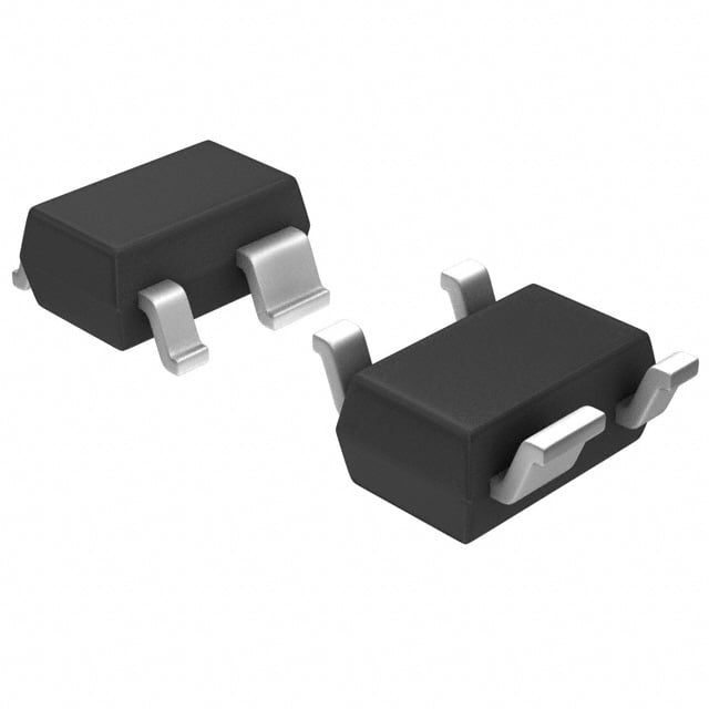
ICGOO在线商城 > 集成电路(IC) > PMIC - 监控器 > ADM6713LAKSZ-REEL7
- 型号: ADM6713LAKSZ-REEL7
- 制造商: Analog
- 库位|库存: xxxx|xxxx
- 要求:
| 数量阶梯 | 香港交货 | 国内含税 |
| +xxxx | $xxxx | ¥xxxx |
查看当月历史价格
查看今年历史价格
ADM6713LAKSZ-REEL7产品简介:
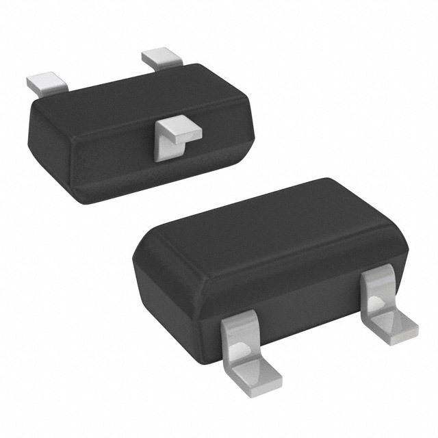
ICGOO电子元器件商城为您提供ADM6713LAKSZ-REEL7由Analog设计生产,在icgoo商城现货销售,并且可以通过原厂、代理商等渠道进行代购。 ADM6713LAKSZ-REEL7价格参考¥2.96-¥5.93。AnalogADM6713LAKSZ-REEL7封装/规格:PMIC - 监控器, 开路漏极或开路集电极 监控器 1 通道 SC-70-4。您可以下载ADM6713LAKSZ-REEL7参考资料、Datasheet数据手册功能说明书,资料中有ADM6713LAKSZ-REEL7 详细功能的应用电路图电压和使用方法及教程。
| 参数 | 数值 |
| 产品目录 | 集成电路 (IC)半导体 |
| 描述 | IC SUPERVISOR OD 4.63V SC70-4监控电路 Microprocessor Reset Circuit IC |
| 产品分类 | |
| 品牌 | Analog Devices Inc |
| 产品手册 | |
| 产品图片 |
|
| rohs | 符合RoHS无铅 / 符合限制有害物质指令(RoHS)规范要求 |
| 产品系列 | 电源管理 IC,监控电路,Analog Devices ADM6713LAKSZ-REEL7- |
| NumberofInputsMonitored | 1 Input |
| 数据手册 | |
| 产品型号 | ADM6713LAKSZ-REEL7 |
| 产品目录页面 | |
| 产品种类 | 监控电路 |
| 人工复位 | Manual Reset |
| 供应商器件封装 | SC-70-4 |
| 其它名称 | ADM6713LAKSZ-REEL7CT |
| 功率失效检测 | No |
| 包装 | 剪切带 (CT) |
| 受监控电压数 | 1 |
| 商标 | Analog Devices |
| 复位 | 低有效 |
| 复位超时 | 最小为 140 ms |
| 安装类型 | 表面贴装 |
| 安装风格 | SMD/SMT |
| 封装 | Reel |
| 封装/外壳 | SC-82A,SOT-343 |
| 封装/箱体 | SC70-4 |
| 工作温度 | -40°C ~ 125°C |
| 工作电源电流 | 35 uA |
| 工厂包装数量 | 3000 |
| 最大工作温度 | + 125 C |
| 最小工作温度 | - 40 C |
| 标准包装 | 1 |
| 欠电压阈值 | 4.56 V |
| 电压-阈值 | 4.63V |
| 电池备用开关 | No Backup |
| 电源电压-最大 | 5.5 V |
| 电源电压-最小 | 1 V |
| 监视器 | No Watchdog |
| 类型 | 简单复位/加电复位 |
| 系列 | ADM6713 |
| 芯片启用信号 | No Chip Enable |
| 被监测输入数 | 1 Input |
| 输出 | 开路漏极或开路集电极 |
| 输出类型 | Open Drain, Push-Pull |
| 过电压阈值 | 4.7 V |
| 重置延迟时间 | 640 ms |
| 阈值电压 | 2.5 V, 3 V, 3.3 V, 5 V |






- 商务部:美国ITC正式对集成电路等产品启动337调查
- 曝三星4nm工艺存在良率问题 高通将骁龙8 Gen1或转产台积电
- 太阳诱电将投资9.5亿元在常州建新厂生产MLCC 预计2023年完工
- 英特尔发布欧洲新工厂建设计划 深化IDM 2.0 战略
- 台积电先进制程称霸业界 有大客户加持明年业绩稳了
- 达到5530亿美元!SIA预计今年全球半导体销售额将创下新高
- 英特尔拟将自动驾驶子公司Mobileye上市 估值或超500亿美元
- 三星加码芯片和SET,合并消费电子和移动部门,撤换高东真等 CEO
- 三星电子宣布重大人事变动 还合并消费电子和移动部门
- 海关总署:前11个月进口集成电路产品价值2.52万亿元 增长14.8%



PDF Datasheet 数据手册内容提取
Microprocessor Supervisory Circuit in 4-Lead SC70 Data Sheet ADM6711/ADM6713 FEATURES FUNCTIONAL BLOCK DIAGRAMS Specified over temperature ADM6711 Low power consumption (12 μA) Precision monitoring of 2.5 V, 3 V, 3.3 V, VCC RESET and 5 V power supply voltages VREF GEN2E40RmAsTOR RESET Reset timeout period of 140 ms (minimum) Manual reset input OuPtpuusht -sptauglle RsE SET output (ADM6711) MR DEBOUNCE GND 03754-011 Open-drain RESET output (ADM6713) Figure 1. Reset assertion down to 1 V V CC ADM6713 Power supply glitch immunity 4-lead SC70 package VCC RESET GENERATOR RESET APPLICATIONS VREF 240ms Microprocessor systems Computers CInotnetllrioglelenrts i nstruments MR DEBOUNCE GND 03754-001 Figure 2. Automotive systems GENERAL DESCRIPTION The ADM6711/ADM6713 are reset generator circuits suitable The parts are highly reliable with accurate voltage references for use in microprocessor-based systems. They provide a reset and immunity to fast, negative-going transients on V . Low CC signal on power-up, power-down, and whenever the supply current consumption and space-efficient, 4-lead SC70 packaging voltage falls below a preset threshold. In addition, both parts make the ADM6711/ADM6713 ideal for use in low power have a debounced manual reset input so that a reset signal can portable applications. also be initiated with an external switch or logic signal. With six different reset threshold options available ranging from 2.32 V to 4.63 V, the ADM6711/ADM6713 are suitable for VCC *RPULL-UP VCC ADM6711/ MICROPROCESSOR monitoring 2.5 V, 3 V, 3.3 V, and 5 V supplies. A reset timeout ADM6713 SYSTEM of at least 140 ms occurs when V rises above the threshold. CC MR RESET RESET This gives the supply voltage time to stabilize before the microprocessor starts up. GND GND cTohme ApoDnMen6t7s1 a1r eh anse ae dpeudsh. T-phuel lA oDutMpu6t,7 s1o3 noop aednd-ditrioainna lo euxttpeurnt al *ADM6713 ONLY 03754-002 Figure 3. Typical Operating Circuit requires an external pull-up resistor that can be connected to a voltage higher than V , if desired. CC Rev. B Information furnished by Analog Devices is believed to be accurate and reliable. However, no responsibility is assumed by Analog Devices for its use, nor for any infringements of patents or other One Technology Way, P.O. Box 9106, Norwood, MA 02062-9106, U.S.A. rights of third parties that may result from its use. Specifications subject to change without notice. No license is granted by implication or otherwise under any patent or patent rights of Analog Devices. Tel: 781.329.4700 www.analog.com Trademarks and registered trademarks are the property of their respective owners. Fax: 781.461.3113 ©2006–2011 Analog Devices, Inc. All rights reserved.
ADM6711/ADM6713 Data Sheet TABLE OF CONTENTS Features..............................................................................................1 Typical Performance Characteristics..............................................7 Applications.......................................................................................1 Circuit Description............................................................................8 Functional Block Diagrams.............................................................1 Manual Reset Input.......................................................................8 General Description.........................................................................1 Power Supply Glitch Immunity...................................................8 Revision History...............................................................................2 ADM6713 RESET Output Logic Levels.....................................8 Specifications.....................................................................................3 Ensuring a Valid RESET Output Down To V = 0 V............8 CC Absolute Maximum Ratings............................................................5 Outline Dimensions..........................................................................9 ESD Caution..................................................................................5 Ordering Guide.............................................................................9 Pin Configuration and Function Descriptions.............................6 REVISION HISTORY 9/11—Rev. A to Rev. B Changes to Input Threshold Parameter, Table 1..........................4 Updated Outline Dimensions.........................................................9 12/06—Rev. 0 to Rev. A Updated Format..................................................................Universal Changes to Specifications Table......................................................3 Changes to Figure 10........................................................................8 Changes to Ordering Guide............................................................9 8/03—Revision 0: Initial Version Rev. B | Page 2 of 12
Data Sheet ADM6711/ADM6713 SPECIFICATIONS V = full operating range; T = T to T ; V typ = 5 V for L/M models, 3.3 V for T/S models, 3 V for R models, and 2.5 V for Z models, CC A MIN MAX CC unless otherwise noted. Table 1. Parameter Min Typ Max Unit Test Conditions/Comments SUPPLY V Operating Voltage Range 1.0 5.5 V T = 0°C to 70°C CC A 1.2 5.5 V T = −40°C to +125°C A Supply Current 16 35 μA V < 5.5 V, ADM671_L/M, CC T = −40°C to +85°C A 12 30 μA V < 3.6 V, ADM671_R/S/T/Z, CC T = −40°C to +85°C A 60 μA V < 5.5 V, ADM671_L/M, CC T = 85°C to 125°C A 60 μA V < 3.6 V, ADM671_R/S/T/Z, CC T = 85°C to 125°C A RESET VOLTAGE THRESHOLD ADM671_L 4.56 4.63 4.70 V T = 25°C A 4.50 4.75 V T = −40°C to +85°C A 4.44 4.82 V T = 85°C to 125°C A ADM671_M 4.31 4.38 4.45 V T = 25°C A 4.25 4.50 V T = −40°C to +85°C A 4.20 4.56 V T = 85°C to 125°C A ADM671_T 3.04 3.08 3.11 V T = 25°C A 3.00 3.15 V T = −40°C to +85°C A 2.95 3.21 V T = 85°C to 125°C A ADM671_S 2.89 2.93 2.96 V T = 25°C A 2.85 3.00 V T = −40°C to +85°C A 2.81 3.05 V T = 85°C to 125°C A ADM671_R 2.59 2.63 2.66 V T = 25°C A 2.55 2.70 V T = −40°C to +85°C A 2.52 2.74 V T = 85°C to 125°C A ADM671_Z 2.28 2.32 2.35 V T = 25°C A 2.25 2.38 V T = −40°C to +85°C A 2.22 2.42 V T = 85°C to 125°C A RESET THRESHOLD TEMPERATURE COEFFICIENT 30 ppm/°C V to RESET DELAY 20 μs V = V to (V − 100 mV) CC CC TH TH RESET ACTIVE TIMEOUT PERIOD 140 240 460 ms T = −40°C to +85°C A 100 640 ms T = 85°C to 125°C A RESET OUTPUT VOLTAGE Low (ADM6711/ADM6713) 0.3 V V = V min, I = 1.2 mA, CC TH SINK ADM671_R/S/T/Z 0.4 V V = V min, I = 3.2 mA, CC TH SINK ADM671_L/M 0.3 V V >1.0 V, I = 50 μA CC SINK High (ADM6711) 0.8 V V V > V max, I = 500 μA, CC CC TH SOURCE ADM6711R/S/T/Z 0.8 V V V > V max, I = 800 μA, CC CC TH SOURCE ADM6711L/M Rev. B | Page 3 of 12
ADM6711/ADM6713 Data Sheet Parameter Min Typ Max Unit Test Conditions/Comments RESET OPEN-DRAIN OUTPUT LEAKAGE CURRENT 1 μA V > V , RESET deasserted CC TH MANUAL RESET (MR) Input Threshold 0.3 V V V CC IL 0.7 V V V CC IH Pull-Up Resistance 10 20 kΩ Minimum Pulse width 1 μs Glitch Immunity 100 ns Reset Delay 200 ns Rev. B | Page 4 of 12
Data Sheet ADM6711/ADM6713 ABSOLUTE MAXIMUM RATINGS T = 25°C, unless otherwise noted. A Table 3. RESET Threshold Options Table 2. Model RESET Threshold (V) Parameter Rating ADM671_L 4.63 V −0.3 V to +6 V ADM671_M 4.38 CC RESET (Push-Pull) −0.3 V to (V + 0.3 V) ADM671_T 3.08 CC RESET (Open-Drain) −0.3 V to +6 V ADM671_S 2.93 ADM671_R 2.63 MR −0.3 V to (V + 0.3 V) CC ADM671_Z 2.32 Input Current VCC, MR 20 mA Output Current ESD CAUTION RESET 20 mA Rate of Rise, V 100 V/μs CC θ Thermal Impedance, SC70 146°C/W JA Operating Temperature Range −40°C to +125°C Storage Temperature Range −65°C to +150°C Lead Temperature (Soldering, 10 sec) 300°C Stresses above those listed under Absolute Maximum Ratings may cause permanent damage to the device. This is a stress rating only; functional operation of the device at these or any other conditions above those indicated in the operational section of this specification is not implied. Exposure to absolute maximum rating conditions for extended periods may affect device reliability. Rev. B | Page 5 of 12
ADM6711/ADM6713 Data Sheet PIN CONFIGURATION AND FUNCTION DESCRIPTIONS GND 1 ADM6711/ 4 VCC ADM6713 TOP VIEW (Not to Scale) RESET 2 3 MR 03754-003 Figure 4. Pin Configuration Table 4. Pin Function Descriptions Pin No. Mnemonic Description 1 GND Ground Reference for All Signals (0 V). 2 RESET Active Low Logic Input. RESET remains low while V is below the reset threshold and remains low for CC 240 ms (typical) after V rises above the reset threshold. CC 3 MR Manual Reset. This active low debounced input ignores input pulses of 100 ns (typical) and is guaranteed to accept input pulses greater than 1 μs. Leave floating when not used. 4 V Supply Voltage Being Monitored. CC Rev. B | Page 6 of 12
Data Sheet ADM6711/ADM6713 TYPICAL PERFORMANCE CHARACTERISTICS 12 1.007 1.006 10 IDD @ VCC = 5.5V D 1.005 L O H 1.004 S E 8 R 1.003 A) IDD @ VCC = 3V ET TH 1.002 I (µDD 6 D RES 11..000010 E 4 LIZ 0.999 A M 0.998 R O 2 IDD @ VCC = 1V N 0.997 0 03754-004 00..999965 03754-008 –40 –20 0 20 30 50 70 85 100 120 –40 –20 0 20 30 50 70 85 100 120 TEMPERATURE (°C) TEMPERATURE (°C) Figure 5. Supply Current vs. Temperature Figure 8. RESET Threshold Deviation vs. Temperature 1000 400 900 Y (µs) 800 ON (µs) 335000 SET DELA 760000 T DURATI 250 RE 500 EN 200 N SI ADM671_L/M OW 400 VOD = 20mV RAN 150 D T R- 300 M WE MU 100 PO 200 AXI ADM671_R/S/T/Z 1000–40VVOODD –==2 0210205mmVV0 20 30 50 70 85 100 120 03754-005 M 5000 10 100 10003754-0090 TEMPERATURE (°C) RESET COMPARATOR OVERDRIVE, VTH – VCC(mV) Figure 6. Power-Down RESET Delay vs. Temperature: ADM671_R/ Figure 9. Maximum Transient Duration (Without Causing a RESET Pulse) vs. ADM671_S/ADM671_T/ADM671_Z RESET Comparator Overdrive 900 800 s) Y (µ 700 A L E 600 D T SE 500 RE VOD = 20mV N 400 W O D 300 R- E W 200 O P 1000 VVOODD == 122050mmVV 03754-006 –40 –20 0 20 30 50 70 85 100 120 TEMPERATURE (°C) Figure 7. Power-Down RESET Delay vs. Temperature: ADM671_L/ ADM671_M Rev. B | Page 7 of 12
ADM6711/ADM6713 Data Sheet CIRCUIT DESCRIPTION ADM6713 RESET OUTPUT LOGIC LEVELS The ADM6711/ADM6713 are designed to protect the integrity of a system’s operation by ensuring the proper operation of the The ADM6713 open-drain RESET output is designed for use with system during power-up, power-down, and brownout conditions. an external pull-up resistor. This resistor can be tied to V or CC When the ADM6711/ADM6713 are powered up, the RESET any other reasonable voltage level, offering the flexibility to use output remains low for a period equal to the typical reset active the ADM6713 to drive a variety of different logic level circuitry. timeout period. This is designed to give the system time to power ENSURING A VALID RESET OUTPUT DOWN TO up correctly and for the power supply to stabilize before any V = 0 V CC devices are brought out of reset and allowed to begin executing instructions. Initializing a system in this way provides a more When VCC falls below 0.8 V, the ADM6711/ADM6713 RESET reliable startup for microprocessor systems. output no longer sinks current, and a high impedance CMOS logic input connected to RESET may drift to undetermined MANUAL RESET INPUT logic levels. To eliminate this problem, a pull-down resistor is The ADM6711/ADM6713 manual reset (MR) input allows the connected from RESET to ground. A 100 kΩ resistor is large enough system operator to reset a system by means of an external manual not to load RESET and small enough to pull RESET to ground. switch. Alternatively, a logic signal from another digital circuit can be used to trigger a reset via the MR input. VCC The MR input ignores negative-going pulses faster than 100 ns VCC (typical) and is guaranteed to accept any negative-going input ADM6711 pulse of a duration greater than or equal to 1 μs. The RESET RESET output remains low while MR is held low and for 240 ms 100kΩ I(ft yMpiRc aisl) c aofntenre cMteRd rtoet luornngs c haibglhes. or is used in a noisy environment, GND 03754-010 then placing a 0.1 μF capacitor between the MR input and ground ADM6711 helps to remove any fast, negative-going transients. VCC RESET GENERATOR RESET POWER SUPPLY GLITCH IMMUNITY VREF 240ms The ADM6711/ADM6713 contain internal filtering circuitry that provides immunity to fast transient glitches on the power sshuopwpliyn gli nthee. Fmigaxuirme u9m ill tursatnrsaiteenst g dluitrcaht iiomn mwuitnhoituyt pcearufsoirnmg aa nrecsee bt y MR DEBOUNCE GND 03754-011 Figure 10. Ensuring a Valid RESET Output Down to VCC = 0 V pulse for glitches with amplitudes in the range of 1 mV to 1000 mV. Glitch immunity makes the ADM6711/ADM6713 suitable for use in noisy environments. Mounting a 0.1 μF decoupling capacitor as close as possible to the V pin improves glitch CC immunity further. Rev. B | Page 8 of 12
Data Sheet ADM6711/ADM6713 OUTLINE DIMENSIONS 2.20 1.80 1.35 1.15 4 3 2.40 1.80 1 2 0.65BSC 0.50BSC 1.00 1.10 0.40 0.80 0.80 0.10 0.10MAX SEATING 0.18 0.30 COPLANARITY *0.70 PLANE 0.10 0.10 0.10 0.30 0.50 0.15 *PEAXCCEKPATGFEOORUWTLIDINTEHCOOFRPRINES2PAOSNSDHSOINWFNU.LLTOEIAJSC82 072809-A Figure 11. 4-Lead Thin Shrink Small Outline Transistor Package [SC70] (KS-4) Dimensions shown in millimeters ORDERING GUIDE RESET Temperature Package Package Ordering Model1 Threshold (V) Range Description Option Quantity (k) Branding ADM6711LAKS-REEL 4.63 −40°C to +125°C 4-Lead SC70 KS-4 10 M0B ADM6711LAKSZ-REEL 4.63 −40°C to +125°C 4-Lead SC70 KS-4 10 M4U ADM6711LAKSZ-REEL7 4.63 −40°C to +125°C 4-Lead SC70 KS-4 3 M4U ADM6711MAKS-REEL 4.38 −40°C to +125°C 4-Lead SC70 KS-4 10 M0C ADM6711MAKS-REEL7 4.38 −40°C to +125°C 4-Lead SC70 KS-4 3 M0C ADM6711MAKSZ-REEL7 4.38 −40°C to +125°C 4-Lead SC70 KS-4 3 M86 ADM6711TAKS-REEL 3.08 −40°C to +125°C 4-Lead SC70 KS-4 10 M0D ADM6711TAKSZ-REEL 3.08 −40°C to +125°C 4-Lead SC70 KS-4 10 M4A ADM6711TAKS-REEL7 3.08 −40°C to +125°C 4-Lead SC70 KS-4 3 M0D ADM6711TAKSZ-REEL7 3.08 −40°C to +125°C 4-Lead SC70 KS-4 3 M4A ADM6711SAKS-REEL 2.93 −40°C to +125°C 4-Lead SC70 KS-4 10 M0E ADM6711SAKSZ-REEL 2.93 −40°C to +125°C 4-Lead SC70 KS-4 10 M4B ADM6711SAKS-REEL7 2.93 −40°C to +125°C 4-Lead SC70 KS-4 3 M0E ADM6711SAKSZ-REEL7 2.93 −40°C to +125°C 4-Lead SC70 KS-4 3 M4B ADM6711RAKS-REEL 2.63 −40°C to +125°C 4-Lead SC70 KS-4 10 M0F ADM6711RAKSZ-REEL 2.63 −40°C to +125°C 4-Lead SC70 KS-4 10 M5F ADM6711RAKS-REEL7 2.63 −40°C to +125°C 4-Lead SC70 KS-4 3 M0F ADM6711RAKSZ-REEL7 2.63 −40°C to +125°C 4-Lead SC70 KS-4 3 M5F ADM6711ZAKS-REEL 2.32 −40°C to +125°C 4-Lead SC70 KS-4 10 M0G ADM6711ZAKSZ-REEL 2.32 −40°C to +125°C 4-Lead SC70 KS-4 10 M4H ADM6711ZAKS-REEL7 2.32 −40°C to +125°C 4-Lead SC70 KS-4 3 M0G ADM6711ZAKSZ-REEL7 2.32 −40°C to +125°C 4-Lead SC70 KS-4 3 M4H ADM6713LAKS-REEL 4.63 −40°C to +125°C 4-Lead SC70 KS-4 10 M0H ADM6713LAKSZ-REEL 4.63 −40°C to +125°C 4-Lead SC70 KS-4 10 M87 ADM6713LAKSZ-REEL7 4.63 −40°C to +125°C 4-Lead SC70 KS-4 3 M87 ADM6713MAKS-REEL 4.38 −40°C to +125°C 4-Lead SC70 KS-4 10 M0J ADM6713MAKS-REEL7 4.38 −40°C to +125°C 4-Lead SC70 KS-4 3 M0J ADM6713MAKSZ-REEL7 4.38 −40°C to +125°C 4-Lead SC70 KS-4 3 M88 ADM6713TAKS-REEL 3.08 −40°C to +125°C 4-Lead SC70 KS-4 10 M0K Rev. B | Page 9 of 12
ADM6711/ADM6713 Data Sheet RESET Temperature Package Package Ordering Model1 Threshold (V) Range Description Option Quantity (k) Branding ADM6713TAKS-REEL7 3.08 −40°C to +125°C 4-Lead SC70 KS-4 3 M0K ADM6713TAKSZ-REEL7 3.08 −40°C to +125°C 4-Lead SC70 KS-4 3 M89 ADM6713SAKS-REEL 2.93 −40°C to +125°C 4-Lead SC70 KS-4 10 M0L ADM6713SAKSZ-REEL 2.93 −40°C to +125°C 4-Lead SC70 KS-4 10 M57 ADM6713SAKS-REEL7 2.93 −40°C to +125°C 4-Lead SC70 KS-4 3 M0L ADM6713SAKSZ-REEL7 2.93 −40°C to +125°C 4-Lead SC70 KS-4 3 M57 ADM6713RAKS-REEL 2.63 −40°C to +125°C 4-Lead SC70 KS-4 10 M0M ADM6713RAKSZ-REEL 2.63 −40°C to +125°C 4-Lead SC70 KS-4 10 M4S ADM6713RAKS-REEL7 2.63 −40°C to +125°C 4-Lead SC70 KS-4 3 M0M ADM6713RAKSZ-REEL7 2.63 −40°C to +125°C 4-Lead SC70 KS-4 3 M4S ADM6713ZAKS-REEL 2.32 −40°C to +125°C 4-Lead SC70 KS-4 10 M0N ADM6713ZAKSZ-REEL 2.32 −40°C to +125°C 4-Lead SC70 KS-4 10 M4R ADM6713ZAKS-REEL7 2.32 −40°C to +125°C 4-Lead SC70 KS-4 3 M0N ADM6713ZAKSZ-REEL7 2.32 −40°C to +125°C 4-Lead SC70 KS-4 3 M4R 1 Z = RoHS Compliant Part. Rev. B | Page 10 of 12
Data Sheet ADM6711/ADM6713 NOTES Rev. B | Page 11 of 12
ADM6711/ADM6713 Data Sheet NOTES ©2006–2011 Analog Devices, Inc. All rights reserved. Trademarks and registered trademarks are the property of their respective owners. D03754-0-9/11(B) Rev. B | Page 12 of 12
Mouser Electronics Authorized Distributor Click to View Pricing, Inventory, Delivery & Lifecycle Information: A nalog Devices Inc.: ADM6711TAKSZ-REEL7 ADM6711TAKSZ-REEL ADM6711LAKS-REEL ADM6711LAKSZ-REEL ADM6711LAKSZ- REEL7 ADM6711MAKS-REEL ADM6711MAKS-REEL7 ADM6711MAKSZ-REEL7 ADM6711RAKS-REEL7 ADM6711RAKSZ-REEL ADM6711RAKSZ-REEL7 ADM6711SAKS-REEL7 ADM6711SAKSZ-REEL7 ADM6711TAKS- REEL ADM6711ZAKS-REEL ADM6711ZAKS-REEL7 ADM6711ZAKSZ-REEL ADM6711ZAKSZ-REEL7 ADM6713LAKSZ-REEL ADM6713LAKSZ-REEL7 ADM6713MAKS-REEL ADM6713MAKS-REEL7 ADM6713MAKSZ- REEL7 ADM6713RAKS-REEL7 ADM6713RAKSZ-REEL7 ADM6713SAKS-REEL7 ADM6713SAKSZ-REEL ADM6713SAKSZ-REEL7 ADM6713TAKS-REEL ADM6713TAKS-REEL7 ADM6713TAKSZ-REEL7 ADM6713ZAKS- REEL ADM6713ZAKS-REEL7 ADM6713ZAKSZ-REEL ADM6713ZAKSZ-REEL7 ADM6713RAKS-REEL ADM6713RAKSZ-REEL ADM6711SAKS-REEL ADM6713SAKS-REEL ADM6713LAKS-REEL ADM6711RAKS-REEL ADM6711SAKSZ-REEL
 Datasheet下载
