ICGOO在线商城 > 集成电路(IC) > 数据采集 - 模数转换器 > ADC0831
- 型号: ADC0831
- 制造商: Parallax
- 库位|库存: xxxx|xxxx
- 要求:
| 数量阶梯 | 香港交货 | 国内含税 |
| +xxxx | $xxxx | ¥xxxx |
查看当月历史价格
查看今年历史价格
ADC0831产品简介:
ICGOO电子元器件商城为您提供ADC0831由Parallax设计生产,在icgoo商城现货销售,并且可以通过原厂、代理商等渠道进行代购。 ADC0831价格参考。ParallaxADC0831封装/规格:数据采集 - 模数转换器, 8 Bit Analog to Digital Converter 1 Input 1 。您可以下载ADC0831参考资料、Datasheet数据手册功能说明书,资料中有ADC0831 详细功能的应用电路图电压和使用方法及教程。
| 参数 | 数值 |
| 品牌 | Parallax |
| 产品目录 | 半导体 |
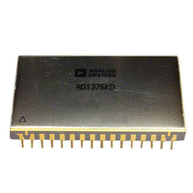
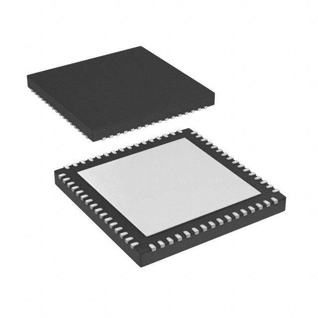
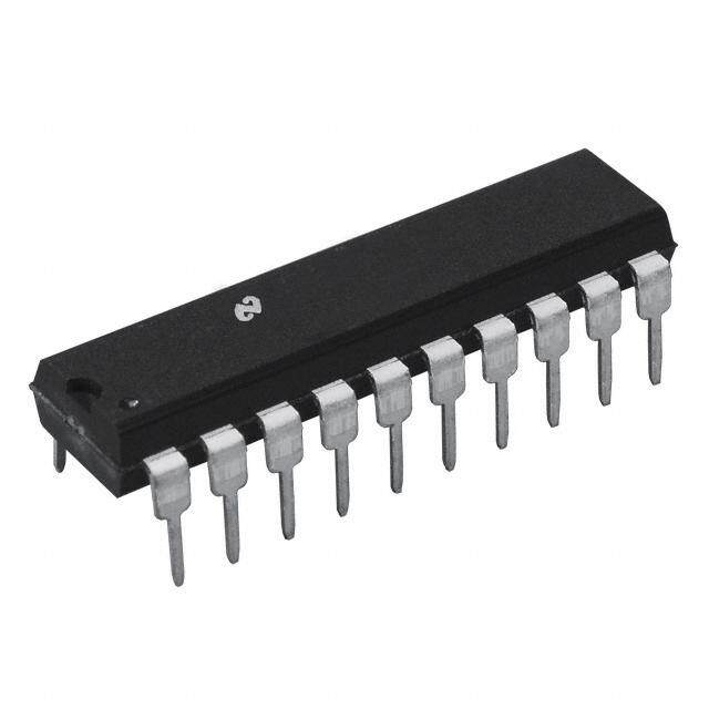
| 描述 | 模数转换器 - ADC 8-bit ADC DIP ADC0831 |
| 产品分类 | 集成电路 - IC |
| 产品手册 | |
| 产品图片 |
|
| rohs | 符合RoHS |
| 产品系列 | 数据转换器IC,模数转换器 - ADC,Parallax ADC0831 |
| mouser_ship_limit | 该产品可能需要其他文件才能进口到中国。 |
| 产品型号 | ADC0831 |
| 产品种类 | 模数转换器 - ADC |
| 分辨率 | 8 bit |
| 单位重量 | 2.268 g |
| 商标 | Parallax |
| 安装风格 | Through Hole |
| 封装/箱体 | DIP-8 |
| 工作电源电压 | 5 V |
| 接口类型 | Serial |
| 最大功率耗散 | 0.8 W |
| 最大工作温度 | + 70 C |
| 最小工作温度 | 0 C |
| 电压参考 | 5 V |
| 结构 | SAR |
| 转换器数量 | 1 |
| 输入类型 | Differential |
| 通道数量 | 1 Channel |


- 商务部:美国ITC正式对集成电路等产品启动337调查
- 曝三星4nm工艺存在良率问题 高通将骁龙8 Gen1或转产台积电
- 太阳诱电将投资9.5亿元在常州建新厂生产MLCC 预计2023年完工
- 英特尔发布欧洲新工厂建设计划 深化IDM 2.0 战略
- 台积电先进制程称霸业界 有大客户加持明年业绩稳了
- 达到5530亿美元!SIA预计今年全球半导体销售额将创下新高
- 英特尔拟将自动驾驶子公司Mobileye上市 估值或超500亿美元
- 三星加码芯片和SET,合并消费电子和移动部门,撤换高东真等 CEO
- 三星电子宣布重大人事变动 还合并消费电子和移动部门
- 海关总署:前11个月进口集成电路产品价值2.52万亿元 增长14.8%


PDF Datasheet 数据手册内容提取
A August1999 D C 0 8 3 1 ADC0831/ADC0832/ADC0834/ADC0838 / A 8-Bit Serial I/O A/D Converters with Multiplexer Options D C 0 General Description n Operatesratiometricallyorwith5VDCvoltage 8 reference 3 TheADC0831seriesare8-bitsuccessiveapproximationA/D n Nozeroorfull-scaleadjustrequired 2 converterswithaserialI/Oandconfigurableinputmultiplex- n 2-,4-or8-channelmultiplexeroptionswithaddresslogic /A ers with up to 8 channels. The serial I/O is configured to complywiththeNSCMICROWIRE™serialdataexchange n Shuntregulatorallowsoperationwithhighvoltage D standardforeasyinterfacetotheCOPS™familyofproces- supplies C sors,andcaninterfacewithstandardshiftregistersorµPs. n 0Vto5Vinputrangewithsingle5Vpowersupply 08 The2-,4-or8-channelmultiplexersaresoftwareconfigured n Remoteoperationwithserialdigitaldatalink 3 forsingle-endedordifferentialinputsaswellaschannelas- n TTL/MOSinput/outputcompatible 4 / signment. n 0.3"standardwidth,8-,14-or20-pinDIPpackage A The differential analog voltage input allows increasing the n 20PinMoldedChipCarrierPackage(ADC0838only) D common-moderejectionandoffsettingtheanalogzeroinput n Surface-MountPackage C voltagevalue.Inaddition,thevoltagereferenceinputcanbe 0 adjustedtoallowencodinganysmalleranalogvoltagespan Key Specifications 8 3 tothefull8bitsofresolution. n Resolution 8Bits 8 Features n TotalUnadjustedError ±1⁄2LSBand±1LSB 8 n SingleSupply 5VDC -B n NSCMICROWIREcompatible—directinterfaceto n LowPower 15mW i COPSfamilyprocessors n ConversionTime 32µs t n Easyinterfacetoallmicroprocessors,oroperates S “stand-alone” e r i a Typical Application l I / O A / D C o n v e r t e r s w i t h M u l t i p l e x e r DS005583-1 O p t i o n s TRI-STATE®isaregisteredtrademarkofNationalSemiconductorCorporation. COPS™andMICROWIRE™aretrademarksofNationalSemiconductorCorporation. ©1999NationalSemiconductorCorporation DS005583 www.national.com
Connection Diagrams ADC08388-ChannelMux SmallOutline/Dual-In-LinePackage ADC08344-ChannelMUX ADC08322-ChannelMUX (WMandN) SmallOutline/Dual-In-LinePackage Dual-In-LinePackage(N) (WMandN) DS005583-31 COMinternallyconnectedtoGND. VREFinternallyconnectedtoVCC. TopView DS005583-30 COMinternallyconnectedtoAGND TopView TopView DS005583-8 TopView TopView ADC08322-ChannelMUX ADC0831Single SmallOutlinePackage(WM) DifferentialInput ADC0831SingleDifferentialInput Dual-In-LinePackage(N) SmallOutlinePackage(WM) DS005583-32 TopView DS005583-41 TopView DS005583-42 TopView ADC08388-ChannelMUX MoldedChipCarrier(PCC) Package(V) DS005583-33 www.national.com 2
Ordering Information PartNumber AnalogInput Total Package Temperature Channels UnadjustedError Range ADC0831CCN 1 ±1 Molded(N) 0˚Cto+70˚C ADC0831CCWM SO(M) 0˚Cto+70˚C ADC0832CIWM 2 ±1 SO(M) −40˚Cto+85˚C ADC0832CCN Molded(N) 0˚Cto+70˚C ADC0832CCWM SO(M) 0˚Cto+70˚C ADC0834BCN 4 ±1⁄2 Molded(N) 0˚Cto+70˚C ADC0834CCN ±1 Molded(N) 0˚Cto+70˚C ADC0834CCWM SO(M) 0˚Cto+70˚C ADC0838BCV 8 ±1⁄2 PCC(V) 0˚Cto+70˚C ADC0838CCV ±1 PCC(V) 0˚Cto+70˚C ADC0838CCN Molded(N) 0˚Cto+70˚C ADC0838CIWM SO(M) −40˚Cto+85˚C ADC0838CCWM SO(M) 0˚Cto+70˚C SeeNSPackageNumberM14B,M20B,N08E,N14A,N20AorV20A 3 www.national.com
AbsoluteMaximumRatings (Notes1,2) LeadTemperature(Soldering10sec.) If Military/Aerospace specified devices are required, Dual-In-LinePackage(Plastic) 260˚C pleasecontacttheNationalSemiconductorSalesOffice/ MoldedChipCarrierPackage Distributorsforavailabilityandspecifications. VaporPhase(60sec.) 215˚C Infrared(15sec.) 220˚C CurrentintoV+(Note3) 15mA ESDSusceptibility(Note5) 2000V SupplyVoltage,V (Note3) 6.5V CC Voltage OperatingRatings (Notes1,2) LogicInputs −0.3VtoV +0.3V CC AnalogInputs −0.3VtoVCC+0.3V SupplyVoltage,VCC 4.5VDCto6.3VDC InputCurrentperPin(Note4) ±5mA TemperatureRange TMIN£ TA£ TMAX Package ±20mA ADC0832/8CIWM −40˚Cto+85˚C StorageTemperature −65˚Cto+150˚C ADC0834BCN, PackageDissipation ADC0838BCV, atT =25˚C(BoardMount) 0.8W ADC0831/2/4/8CCN, A ADC0838CCV, ADC0831/2/4/8CCWM 0˚Cto+70˚C ConverterandMultiplexerElectricalCharacteristics Thefollowingspecificationsapplyfor V =V+=V =5V,V £ V +0.1V,T =T =25˚C,andf =250kHzunlessotherwisespecified.Boldfacelimits CC REF REF CC A j CLK applyfromT toT . MIN MAX Conditions CIWMDevices BCV,CCV,CCWM,BCN andCCNDevices Parameter Typ Tested Design Typ Tested Design Units (Note12) Limit Limit (Note12) Limit Limit (Note13) (Note14) (Note13) (Note14) CONVERTERANDMULTIPLEXERCHARACTERISTICS TotalUnadjustedError VREF=5.00V ADC0838BCV (Note6) ±1⁄2 ±1⁄2 ADC0834BCN ±1⁄2 ±1⁄2 LSB (Max) ADC0838CCV ±1 ±1 ADC0831/2/4/8CCN ±1 ±1 ADC0831/2/4/8CCWM ±1 ±1 ADC0832/8CIWM ±1 MinimumReference 3.5 1.3 3.5 1.3 1.3 kW InputResistance(Note7) MaximumReference 3.5 5.9 3.5 5.4 5.9 kW InputResistance(Note7) MaximumCommon-Mode VCC+0.05 VCC+0.05 VCC+0.05 V InputRange(Note8) MinimumCommon-Mode GND−0.05 GND−0.05 GND−0.05 V InputRange(Note8) DCCommon-ModeError ±1/16 ±1⁄4 ±1/16 ±1⁄4 ±1⁄4 LSB Changeinzero 15mAintoV+ errorfromVCC=5V VCC=N.C. tointernalzener VREF=5V operation(Note3) 1 1 1 LSB VZ,internal MIN 15mAintoV+ 6.3 6.3 6.3 diodebreakdown MAX 8.5 8.5 8.5 V (atV+)(Note3) PowerSupplySensitivity VCC=5V±5% ±1/16 ±1⁄4 ±1⁄4 ±1/16 ±1⁄4 ±1⁄4 LSB IOFF,OffChannelLeakage OnChannel=5V, −0.2 −0.2 −1 µA Current(Note9) OffChannel=0V −1 OnChannel=0V, +0.2 +0.2 +1 µA OffChannel=5V +1 www.national.com 4
ConverterandMultiplexerElectricalCharacteristics Thefollowingspecificationsapplyfor VCC=V+=VREF=5V,VREF£ VCC+0.1V,TA=Tj=25˚C,andfCLK=250kHzunlessotherwisespecified.Boldfacelimits applyfromT toT . (Continued) MIN MAX Conditions CIWMDevices BCV,CCV,CCWM,BCN andCCNDevices Parameter Typ Tested Design Typ Tested Design Units (Note12) Limit Limit (Note12) Limit Limit (Note13) (Note14) (Note13) (Note14) CONVERTERANDMULTIPLEXERCHARACTERISTICS ION,OnChannelLeakage OnChannel=0V, −0.2 −0.2 −1 µA Current(Note9) OffChannel=5V −1 OnChannel=5V, +0.2 +0.2 +1 µA OffChannel=0V +1 DIGITALANDDCCHARACTERISTICS VIN(1),Logical“1”Input VCC=5.25V 2.0 2.0 2.0 V Voltage(Min) VIN(0),Logical“0”Input VCC=4.75V 0.8 0.8 0.8 V Voltage(Max) IIN(1),Logical“1”Input VIN=5.0V 0.005 1 0.005 1 1 µA Current(Max) IIN(0),Logical“0”Input VIN=0V −0.005 −1 −0.005 −1 −1 µA Current(Max) VOUT(1),Logical“1”Output VCC=4.75V Voltage(Min) IOUT=−360µA 2.4 2.4 2.4 V IOUT=−10µA 4.5 4.5 4.5 V VOUT(0),Logical“0”Output VCC=4.75V 0.4 0.4 0.4 V Voltage(Max) IOUT=1.6mA IOUT,TRI-STATEOutput VOUT=0V −0.1 −3 −0.1 −3 −3 µA Current(Max) VOUT=5V 0.1 3 0.1 +3 +3 µA ISOURCE,OutputSource VOUT=0V −14 −6.5 −14 −7.5 −6.5 mA Current(Min) ISINK,OutputSinkCurrent(Min) VOUT=VCC 16 8.0 16 9.0 8.0 mA ICC,SupplyCurrent(Max) ADC0831,ADC0834, 0.9 2.5 0.9 2.5 2.5 mA ADC0838 ADC0832 IncludesLadder 2.3 6.5 2.3 6.5 6.5 mA Current AC Characteristics ThefollowingspecificationsapplyforV =5V,t =t =20nsand25˚Cunlessotherwisespecified. CC r f Typ Tested Design Limit Parameter Conditions (Note12) Limit Limit Units (Note13) (Note14) f ,ClockFrequency Min 10 kHz CLK Max 400 kHz t ,ConversionTime NotincludingMUXAddressingTime 8 1/f C CLK ClockDutyCycle Min 40 % (Note10) Max 60 % t ,CSFallingEdgeor 250 ns SET-UP DataInputValidtoCLK RisingEdge t ,DataInputValid 90 ns HOLD afterCLKRisingEdge 5 www.national.com
AC Characteristics (Continued) ThefollowingspecificationsapplyforV =5V,t =t =20nsand25˚Cunlessotherwisespecified. CC r f Typ Tested Design Limit Parameter Conditions (Note12) Limit Limit Units (Note13) (Note14) t ,t —CLKFalling C =100pF pd1 pd0 L EdgetoOutputDataValid DataMSBFirst 650 1500 ns (Note11) DataLSBFirst 250 600 ns t ,t ,—RisingEdgeof C =10pF,R =10k 125 250 ns 1H 0H L L CStoDataOutputand (seeTRI-STATE®TestCircuits) SARSHi–Z C =100pf,R =2k 500 ns L L C ,CapacitanceofLogic 5 pF IN Input C ,CapacitanceofLogic 5 pF OUT Outputs Note1: AbsoluteMaximumRatingsindicatelimitsbeyondwhichdamagetothedevicemayoccur.DCandACelectricalspecificationsdonotapplywhenoperating thedevicebeyonditsspecifiedoperatingconditions. Note2: Allvoltagesaremeasuredwithrespecttothegroundplugs. Note3: Internalzenerdiodes(6.3to8.5V)areconnectedfromV+toGNDandVCCtoGND.ThezeneratV+canoperateasashuntregulatorandisconnected toVCCviaaconventionaldiode.SincethezenervoltageequalstheA/D’sbreakdownvoltage,thediodeinsuresthatVCCwillbebelowbreakdownwhenthedevice ispoweredfromV+.FunctionalityisthereforeguaranteedforV+operationeventhoughtheresultantvoltageatVCCmayexceedthespecifiedAbsoluteMaxof6.5V. ItisrecommendedthataresistorbeusedtolimitthemaxcurrentintoV+.(SeeFigure3inFunctionalDescriptionSection6.0) Note4: Whentheinputvoltage(VIN)atanypinexceedsthepowersupplyrails(VIN<V−orVIN>V+)theabsolutevalueofcurrentatthatpinshouldbelimited to5mAorless.The20mApackageinputcurrentlimitsthenumberofpinsthatcanexceedthepowersupplyboundarieswitha5mAcurrentlimittofour. Note5: Humanbodymodel,100pFdischargedthrougha1.5kW resistor. Note6: Totalunadjustederrorincludesoffset,full-scale,linearity,andmultiplexererrors. Note7: CannotbetestedforADC0832. Note8: ForVIN(−)‡ VIN(+)thedigitaloutputcodewillbe00000000.Twoon-chipdiodesaretiedtoeachanaloginput(seeBlockDiagram)whichwillforwardconduct foranaloginputvoltagesonediodedropbelowgroundoronediodedropgreaterthantheVCCsupply.Becareful,duringtestingatlowVCClevels(4.5V),ashigh levelanaloginputs(5V)cancausethisinputdiodetoconduct—especiallyatelevatedtemperatures,andcauseerrorsforanaloginputsnearfull-scale.Thespec allows50mVforwardbiasofeitherdiode.ThismeansthataslongastheanalogVINorVREFdoesnotexceedthesupplyvoltagebymorethan50mV,theoutput codewillbecorrect.Toachieveanabsolute0VDCto5VDCinputvoltagerangewillthereforerequireaminimumsupplyvoltageof4.950VDCovertemperaturevaria- tions,initialtoleranceandloading. Note9: Leakagecurrentismeasuredwiththeclocknotswitching. Note10: A40%to60%clockdutycyclerangeinsuresproperoperationatallclockfrequencies.Inthecasethatanavailableclockhasadutycycleoutsideofthese limits,theminimum,timetheclockishighortheminimumtimetheclockislowmustbeatleast1µs.Themaximumtimetheclockcanbehighis60µs.Theclock canbestoppedwhenlowsolongastheanaloginputvoltageremainsstable. Note11: Sincedata,MSBfirst,istheoutputofthecomparatorusedinthesuccessiveapproximationloop,anadditionaldelayisbuiltin(seeBlockDiagram)toallow forcomparatorresponsetime. Note12: Typicalsareat25˚Candrepresentmostlikelyparametricnorm. Note13: TestedlimitsareguaranteedtoNational’sAOQL(AverageOutgoingQualityLevel). Note14: Guaranteedbutnot100%productiontested.Theselimitsarenotusedtocalculateoutgoingqualitylevels. Typical Performance Characteristics UnadjustedOffsetError LinearityErrorvsVREF LinearityErrorvs vsVREFVoltage Voltage Temperature DS005583-43 DS005583-44 DS005583-45 www.national.com 6
Typical Performance Characteristics (Continued) LinearityErrorvsfCLK PowerSupplyCurrentvs OutputCurrentvs Temperature(ADC0838, Temperature ADC0831,ADC0834) DS005583-46 DS005583-48 DS005583-47 Note:ForADC0832addIREF. PowerSupplyCurrent vsf CLK DS005583-29 Leakage Current Test Circuit DS005583-3 7 www.national.com
TRI-STATE Test Circuits and Waveforms t t 1H 0H DS005583-49 DS005583-50 t t 1H 0H DS005583-51 DS005583-52 Timing Diagrams DataInputTiming DataOutputTiming DS005583-24 DS005583-25 ADC0831StartConversionTiming DS005583-26 www.national.com 8
Timing Diagrams (Continued) ADC0831Timing DS005583-27 *LSBfirstoutputnotavailableonADC0831. ADC0832Timing DS005583-28 ADC0834Timing DS005583-5 9 www.national.com
Timing Diagrams (Continued) DS005583-6 g n mi Ti 8 3 8 0 C D A w o l n e ak t is E S e or ef b B S L e h t n i ocks cl 8 1 # e g d e ock cl e ur s e ak M * www.national.com 10
ADC0838 Functional Block Diagram DS005583-7 orcedto f is 0 T C E L E S N. G SI D/ D O of ut p n i DI e h t o t ectly dir ut p n i is DI 2, 3 8 0 C D A e h t or F 1”. “ a o t d e orc f is 0 T C E L E S 1. T C E L ns.SE optioutof otherDinp withothe et functions/pinsarenotavailablADC0834,D1isinputdirectlyCT1isforcedtoa“1”. eofthese1:FortheandSELE *SomNotea“0” 11 www.national.com
Functional Description 1.0MULTIPLEXERADDRESSING Thedesignoftheseconvertersutilizesasample-datacom- In the differential case, it also assigns the polarity of the paratorstructurewhichprovidesforadifferentialanalogin- channels.Differentialinputsarerestrictedtoadjacentchan- puttobeconvertedbyasuccessiveapproximationroutine. nelpairs.Forexamplechannel0andchannel1maybese- The actual voltage converted is always the difference be- lectedasadifferentpairbutchannel0or1cannotactdiffer- tweenanassigned“+”inputterminalanda“−”inputterminal. entially with any other channel. In addition to selecting The polarity of each input terminal of the pair being con- differentialmodethesignmayalsobeselected.Channel0 vertedindicateswhichlinetheconverterexpectstobethe maybeselectedasthepositiveinputandchannel1asthe mostpositive.Iftheassigned“+”inputislessthanthe“−”in- negativeinputorviceversa.Thisprogrammabilityisbestil- puttheconverterrespondswithanallzerosoutputcode. lustratedbytheMUXaddressingcodesshowninthefollow- ingtablesforthevariousproductoptions. Auniqueinputmultiplexingschemehasbeenutilizedtopro- vide multiple analog channels with software-configurable TheMUXaddressisshiftedintotheconverterviatheDIline. single-ended,differential,oranewpseudo-differentialoption Because theADC0831 contains only one differential input whichwillconvertthedifferencebetweenthevoltageatany channelwithafixedpolarityassignment,itdoesnotrequire analoginputandacommonterminal.Theanalogsignalcon- addressing. ditioningrequiredintransducer-baseddataacquisitionsys- ThecommoninputlineontheADC0838canbeusedasa temsissignificantlysimplifiedwiththistypeofinputflexibility. pseudo-differentialinput.Inthismode,thevoltageonthispin Oneconverterpackagecannowhandlegroundreferenced istreatedasthe“−”inputforanyoftheotherinputchannels. inputs and true differential inputs as well as signals with Thisvoltagedoesnothavetobeanalogground;itcanbe somearbitraryreferencevoltage. anyreferencepotentialwhichiscommontoalloftheinputs. AparticularinputconfigurationisassignedduringtheMUX Thisfeatureismostusefulinsingle-supplyapplicationwhere addressingsequence,priortothestartofaconversion.The theanalogcircuitrymaybebiaseduptoapotentialother MUXaddressselectswhichoftheanaloginputsaretobe thangroundandtheoutputsignalsareallreferredtothis enabledandwhetherthisinputissingle-endedordifferential. potential. TABLE1.Multiplexer/PackageOptions Part NumberofAnalogChannels Numberof Number Single-Ended Differential PackagePins ADC0831 1 1 8 ADC0832 2 1 8 ADC0834 4 2 14 ADC0838 8 4 20 www.national.com 12
Functional Description (Continued) TABLE2.MUXAddressing:ADC0838 Single-EndedMUXMode MUXAddress AnalogSingle-EndedChannel# SGL/ ODD/ SELECT 0 1 2 3 4 5 6 7 COM DIF SIGN 1 0 1 0 0 0 + − 1 0 0 1 + − 1 0 1 0 + − 1 0 1 1 + − 1 1 0 0 + − 1 1 0 1 + − 1 1 1 0 + − 1 1 1 1 + − TABLE3.MUXAddressing:ADC0838 DifferentialMUXMode MUXAddress AnalogDifferentialChannel-Pair# SGL/ ODD/ SELECT 0 1 2 3 DIF SIGN 1 0 0 1 2 3 4 5 6 7 0 0 0 0 + − 0 0 0 1 + − 0 0 1 0 + − 0 0 1 1 + − 0 1 0 0 − + 0 1 0 1 − + 0 1 1 0 − + 0 1 1 1 − + TABLE4.MUXAddressing:ADC0834 Single-EndedMUXMode MUXAddress Channel# SGL/ ODD/ SELECT DIF SIGN 1 0 1 2 3 1 0 0 + 1 0 1 + 1 1 0 + 1 1 1 + COMisinternallytiedtoAGND TABLE5.MUXAddressing:ADC0834 DifferentialMUXMode MUXAddress Channel# SGL/ ODD/ SELECT DIF SIGN 1 0 1 2 3 0 0 0 + − 0 0 1 + − 0 1 0 − + 0 1 1 − + 13 www.national.com
Functional Description (Continued) TABLE6.MUXAddressing:ADC0832 Single-EndedMUXMode MUXAddress Channel# SGL/ ODD/ 0 1 DIF SIGN 1 0 + 1 1 + COMisinternallytiedtoAGND TABLE7.MUXAddressing:ADC0832 DifferentialMUXMode MUXAddress Channel# SGL/ ODD/ 0 1 DIF SIGN 0 0 + − 0 1 − + Sincetheinputconfigurationisundersoftwarecontrol,itcan converterpackagewithnoincreaseinpackagesizeandit bemodified,asrequired,ateachconversion.Achannelcan caneliminatethetransmissionoflowlevelanalogsignalsby be treated as a single-ended, ground referenced input for locatingtheconverterrightattheanalogsensor;transmitting oneconversion;thenitcanbereconfiguredaspartofadif- highlynoiseimmunedigitaldatabacktothehostprocessor. ferentialchannelforanotherconversion.Figure1illustrates Tounderstandtheoperationoftheseconvertersitisbestto theinputflexibilitywhichcanbeachieved. refertotheTimingDiagramsandFunctionalBlockDiagram Theanaloginputvoltagesforeachchannelcanrangefrom andtofollowacompleteconversionsequence.Forclaritya 50mVbelowgroundto50mVaboveV (typically5V)with- separatediagramisshownofeachdevice. CC outdegradingconversionaccuracy. 1.AconversionisinitiatedbyfirstpullingtheCS(chipselect) linelow.Thislinemustbeheldlowfortheentireconversion. 2.0THEDIGITALINTERFACE TheconverterisnowwaitingforastartbitanditsMUXas- Amostimportantcharacteristicoftheseconvertersistheir signmentword. serialdatalinkwiththecontrollingprocessor.Usingaserial 2.Aclockisthengeneratedbytheprocessor(ifnotprovided communicationformatofferstwoverysignificantsystemim- continuously)andoutputtotheA/Dclockinput. provements; it allows more function to be included in the www.national.com 14
Functional Description (Continued) 8Single-Ended 8Pseudo-Differential DS005583-53 DS005583-54 4Differential MixedMode DS005583-55 DS005583-56 FIGURE1.AnalogInputMultiplexerOptionsfortheADC0838 3.Oneachrisingedgeoftheclockthestatusofthedatain 7.After 8 clock periods the conversion is completed. The (DI)lineisclockedintotheMUXaddressshiftregister.The SAR status line returns low to indicate this 1⁄2 clock cycle startbitisthefirstlogic“1”thatappearsonthisline(alllead- later. ingzerosareignored).Followingthestartbittheconverter 8.Iftheprogrammerprefers,thedatacanbeprovidedinan expectsthenext2to4bitstobetheMUXassignmentword. LSBfirstformat[thismakesuseoftheshiftenable(SE)con- 4.Whenthestartbithasbeenshiftedintothestartlocation trolline].All8bitsoftheresultarestoredinanoutputshift oftheMUXregister,theinputchannelhasbeenassigned register.OndeviceswhichdonotincludetheSEcontrolline, andaconversionisabouttobegin.Anintervalof1⁄2clockpe- thedata,LSBfirst,isautomaticallyshiftedouttheDOline, riod(wherenothinghappens)isautomaticallyinsertedtoal- aftertheMSBfirstdatastream.TheDOlinethengoeslow lowtheselectedMUXchanneltosettle.TheSARstatusline andstayslowuntilCSisreturnedhigh.OntheADC0838the goeshighatthistimetosignalthataconversionisnowin SElineisbroughtoutandifheldhigh,thevalueoftheLSB progress and the DI line is disabled (it no longer accepts remainsvalidontheDOline.WhenSEisforcedlow,the data). dataisthenclockedoutLSBfirst.TheADC0831isanexcep- 5.Thedataout(DO)linenowcomesoutofTRI-STATEand tioninthatitsdataisonlyoutputinMSBfirstformat. providesaleadingzeroforthisoneclockperiodofMUXset- 9.AllinternalregistersareclearedwhentheCSlineishigh. tlingtime. Ifanotherconversionisdesired,CSmustmakeahightolow 6.Whentheconversionbegins,theoutputoftheSARcom- transitionfollowedbyaddressinformation. parator,whichindicateswhethertheanaloginputisgreater The DI and DO lines can be tied together and controlled than(high)orlessthan(low)eachsuccessivevoltagefrom throughabidirectionalprocessorI/Obitwithonewire.Thisis theinternalresistorladder,appearsattheDOlineoneach possiblebecausetheDIinputisonly“looked-at”duringthe fallingedgeoftheclock.Thisdataistheresultoftheconver- MUXaddressingintervalwhiletheDOlineisstillinahigh sionbeingshiftedout(withtheMSBcomingfirst)andcanbe impedancestate. readbytheprocessorimmediately. 15 www.national.com
Functional Description (Continued) For absolute accuracy, where the analog input varies be- tweenveryspecificvoltagelimits,thereferencepincanbe 3.0REFERENCECONSIDERATIONS biasedwithatimeandtemperaturestablevoltagesource. Thevoltageappliedtothereferenceinputtotheseconvert- TheLM385andLM336referencediodesaregoodlowcur- ersdefinesthevoltagespanoftheanaloginput(thediffer- rentdevicestousewiththeseconverters. ence between V and V ) over which the 256 ThemaximumvalueofthereferenceislimitedtotheV IN(MAX) IN(MIN) CC possibleoutputcodesapply.Thedevicescanbeusedinei- supplyvoltage.Theminimumvalue,however,canbequite therratiometricapplicationsorinsystemsrequiringabsolute small(seeTypicalPerformanceCharacteristics)toallowdi- accuracy.Thereferencepinmustbeconnectedtoavoltage rectconversionsoftransduceroutputsprovidinglessthana sourcecapableofdrivingthereferenceinputresistanceof 5Voutputspan.Particularcaremustbetakenwithregardto typically3.5kW .Thispinisthetopofaresistordividerstring noisepickup,circuitlayoutandsystemerrorvoltagesources usedforthesuccessiveapproximationconversion. whenoperatingwithareducedspanduetotheincreased Inaratiometricsystem,theanaloginputvoltageispropor- sensitivityoftheconverter(1LSBequalsVREF/256). tionaltothevoltageusedfortheA/Dreference.Thisvoltage istypicallythesystempowersupply,sotheV pincanbe REF tiedtoV (doneinternallyontheADC0832).Thistechnique CC relaxesthestabilityrequirementsofthesystemreferenceas theanaloginputandA/Dreferencemovetogethermaintain- ingthesameoutputcodeforagiveninputcondition. DS005583-57 DS005583-58 a)Ratiometric b)AbsolutewithareducedSpan FIGURE2.ReferenceExamples 4.0THEANALOGINPUTS V isitspeakvoltagevalue PEAK Themostimportantfeatureoftheseconvertersisthatthey andf ,istheA/Dclockfrequency. CLK canbelocatedrightattheanalogsignalsourceandthrough Fora60Hzcommon-modesignaltogeneratea1⁄4LSBerror justafewwirescancommunicatewithacontrollingproces- (» 5mV)withtheconverterrunningat250kHz,itspeakvalue sorwithahighlynoiseimmuneserialbitstream.Thisinitself wouldhavetobe6.63Vwhichwouldbelargerthanallowed greatly minimizes circuitry to maintain analog signal accu- asitexceedsthemaximumanaloginputlimits. racy which otherwise is most susceptible to noise pickup. Duetothesamplingnatureoftheanaloginputsshortspikes However,afewwordsareinorderwithregardtotheanalog of current enter the “+” input and exit the “−” input at the inputs should the input be noisy to begin with or possibly clock edges during the actual conversion. These currents ridingonalargecommon-modevoltage. decayrapidlyanddonotcauseerrorsastheinternalcom- The differential input of these converters actually reduces paratorisstrobedattheendofaclockperiod.Bypassca- theeffectsofcommon-modeinputnoise,asignalcommon pacitorsattheinputswillaveragethesecurrentsandcause tobothselected“+”and“−”inputsforaconversion(60Hzis aneffectiveDCcurrenttoflowthroughtheoutputresistance mosttypical).Thetimeintervalbetweensamplingthe“+”in- oftheanalogsignalsource.Bypasscapacitorsshouldnotbe putandthenthe“−”inputis1⁄2ofaclockperiod.Thechange usedifthesourceresistanceisgreaterthan1kW . inthecommon-modevoltageduringthisshorttimeinterval Thissourceresistancelimitationisimportantwithregardto can cause conversion errors. For a sinusoidal the DC leakage currents of input multiplexer as well. The common-modesignalthiserroris: worst-caseleakagecurrentof ±1µAovertemperaturewill createa1mVinputerrorwitha1kW sourceresistance.An opampRCactivelowpassfiltercanprovidebothimped- ancebufferingandnoisefilteringshouldahighimpedance signalsourceberequired. wheref isthefrequencyofthecommon-modesignal, CM www.national.com 16
Functional Description (Continued) 5.0OPTIONALADJUSTMENTS 5.1ZeroError ThezerooftheA/Ddoesnotrequireadjustment.Ifthemini- mumanaloginputvoltagevalue,V ,isnotgrounda IN(MIN) zerooffsetcanbedone.Theconvertercanbemadetoout- put00000000digitalcodeforthisminimuminputvoltageby biasinganyV (−)inputatthisV value.Thisutilizes IN IN(MIN) thedifferentialmodeoperationoftheA/D. ThezeroerroroftheA/Dconverterrelatestothelocationof thefirstriserofthetransferfunctionandcanbemeasuredby groundingtheV (−)inputandapplyingasmallmagnitude IN DS005583-11 positivevoltagetotheV (+)input.Zeroerroristhediffer- IN FIGURE3.AnOn-ChipShuntRegulatorDiode encebetweentheactualDCinputvoltagewhichisneces- sarytojustcauseanoutputdigitalcodetransitionfrom0000 Thiszenerisintendedforuseasashuntvoltageregulatorto 0000to00000001andtheideal1⁄2LSBvalue(1⁄2LSB=9.8 eliminatetheneedforanyadditionalregulatingcomponents. mVforV =5.000V ). REF DC Thisismostdesirableiftheconverteristoberemotelylo- catedfromthesystempowersource.Figure4andFigure5il- 5.2Full-Scale lustratetwousefulapplicationsofthison-boardzenerwhen Thefull-scaleadjustmentcanbemadebyapplyingadiffer- anexternaltransistorcanbeafforded. entialinputvoltagewhichis11⁄2LSBdownfromthedesired AnimportantuseoftheinterconnectingdiodebetweenV+ analogfull-scalevoltagerangeandthenadjustingthemag- andV isshowninFigure6andFigure7.Here,thisdiode nitudeoftheV input(orV fortheADC0832)foradigi- CC REF CC isusedasarectifiertoallowtheV supplyfortheconverter taloutputcodewhichisjustchangingfrom11111110to1111 CC tobederivedfromtheclock.Thelowcurrentrequirementsof 1111. theA/Dandtherelativelyhighclockfrequenciesused(typi- 5.3AdjustingforanArbitraryAnalogInputVoltage callyintherangeof10k–400kHz)allowsusingthesmall Range valuefiltercapacitorshowntokeeptherippleontheVCCline IftheanalogzerovoltageoftheA/Disshiftedawayfrom towellunder1⁄4ofanLSB.Theshuntzenerregulatorcan also be used in this mode. This requires a clock voltage ground(forexample,toaccommodateananaloginputsignal swingwhichisinexcessofV .Acurrentlimitforthezeneris which does not go to ground), this new zero reference Z needed,eitherbuiltintotheclockgeneratororaresistorcan should be properly adjusted first.AVIN (+) voltage which beusedfromtheCLKpintotheV+pin. equalsthisdesiredzeroreferenceplus1⁄2LSB(wherethe LSBiscalculatedforthedesiredanalogspan,using1LSB= analog span/256) is applied to selected “+” input and the zeroreferencevoltageatthecorresponding“−”inputshould thenbeadjustedtojustobtainthe00 to01 codetran- HEX HEX sition. Thefull-scaleadjustmentshouldbemade[withtheproper V (−)voltageapplied]byforcingavoltagetotheV (+)in- IN IN putwhichisgivenby: where: V =thehighendoftheanaloginputrange MAX and V = the low end (the offset zero) of the analog MIN range. (Botharegroundreferenced.) TheV (orV )voltageisthenadjustedtoprovideacode REF CC change from FE to FF . This completes the adjust- HEX HEX mentprocedure. 6.0POWERSUPPLY AuniquefeatureoftheADC0838andADC0834istheinclu- sion of a zener diode connected from the V+ terminal to groundwhichalsoconnectstotheV terminal(whichisthe CC actualconvertersupply)throughasilicondiode,asshownin Figure3.(Note3) 17 www.national.com
Applications DS005583-12 FIGURE4.OperatingwithaTemperature CompensatedReference DS005583-35 *4.5V£ VCC£ 6.3V FIGURE6.GeneratingV fromtheConverterClock CC DS005583-34 DS005583-36 FIGURE5.UsingtheA/Das theSystemSupplyRegulator *4.5V£ VCC£ 6.3V FIGURE7.RemoteSensing— ClockandPoweron1Wire DigitalLinkandSampleControllingSoftwareforthe SeriallyOrientedCOP420andtheBitProgrammableI/OINS8048 DS005583-13 www.national.com 18
Applications (Continued) 8048CODINGEXAMPLE Mnemonic Instruction COPCODINGEXAMPLE START: ANL P1, ;SELECTA/D(CS=0) Mnemonic Instruction #0F7H LEI ENABLESSIO’sINPUTANDOUTPUT MOV B,#5 ;BITCOUNTER‹ 5 SC C=1 MOV A, ;A‹ MUXADDRESS OGI G0=0(CS=0) #ADDR CLRA CLEARSACCUMULATOR LOOP1: RRC A ;CY‹ ADDRESSBIT AISC1 LOADSACCUMULATORWITH1 JC ONE ;TESTBIT XAS EXCHANGESSIOWITH ;BIT=0 ACCUMULATOR ZERO: ANL P1, ;DI‹ 0 ANDSTARTSSKCLOCK #0FEH LDD LOADSMUXADDRESSFROMRAM JMP CONT ;CONTINUE INTOACCUMULATOR ;BIT=1 NOP — ONE: ORL P1,#1 ;DI‹ 1 XAS LOADSMUXADDRESSFROM CONT: CALL PULSE ;PULSESK0fi 1fi 0 ACCUMULATORTOSIOREGISTER DJNZ B,LOOP ;CONTINUEUNTIL › 1 DONE 8INSTRUCTIONS CALL PULSE ;EXTRACLOCKFOR fl SYNC XAS READSHIGHORDERNIBBLE(4BITS) MOV B,#8 ;BITCOUNTER‹ 8 INTOACCUMULATOR LOOP2: CALL PULSE ;PULSESK0fi 1fi 0 XIS PUTSHIGHORDERNIBBLEINTORAM IN A,P1 ;CY‹ DO CLRA CLEARSACCUMULATOR RRC A RC C=0 RRC A XAS READSLOWORDERNIBBLEINTO MOV A,C ;A‹ RESULT ACCUMULATORANDSTOPSSK RLC A ;A(0)‹ BITANDSHIFT XIS PUTSLOWORDERNIBBLEINTORAM MOV C,A ;C‹ RESULT OGI G0=1(CS=1) DJNZ B,LOOP ;CONTINUEUNTIL 2 DONE LEI DISABLESSIO’sINPUTANDOUTPUT RETR ;PULSESUBROUTINE PULSE: ORL P1,#04 ;SK‹ 1 NOP ;DELAY ANL P1, ;SK‹ 0 #0FBH RET 19 www.national.com
Applications (Continued) A“Stand-Alone”Hook-UpforADC0838Evaluation DS005583-59 *PinoutsshownforADC0838. Forallotherproductstieto pinfunctionsasshown. Low-CostRemoteTemperatureSensor DS005583-60 www.national.com 20
Applications (Continued) DigitizingaCurrentFlow DS005583-15 OperatingwithRatiometricTransducers DS005583-37 *VIN(−)=0.15VCC 15%ofVCC£ VXDR£ 85%ofVCC 21 www.national.com
Applications (Continued) SpanAdjust:0V£ V £ 3V IN DS005583-61 Zero-ShiftandSpanAdjust:2V£ V £ 5V IN DS005583-62 www.national.com 22
Applications (Continued) ObtainingHigherResolution DS005583-63 a)9-BitA/D DS005583-64 Controllerperformsaroutinetodeterminewhichinputpolarity(9-bitexample)orwhichchannelpair(10-bitexample)providesanon-zerooutputcode.This informationprovidestheextrabits. b)10-BitA/D 23 www.national.com
Applications (Continued) ProtectingtheInput DS005583-18 Diodesare1N914 HighAccuracyComparators DS005583-38 DO=all1sif+VIN>−VIN DO=all0sif+VIN<−VIN www.national.com 24
Applications (Continued) DigitalLoadCell DS005583-19 •Usesonemorewirethanloadcellitself •Twomini-DIPscouldbemountedinsideloadcellfordigitaloutputtransducer •Electronicoffsetandgaintrimsrelaxmechanicalspecsforgaugefactorandoffset •Lowlevelcelloutputisconvertedimmediatelyforhighnoiseimmunity 4mA-20mACurrentLoopConverter DS005583-20 •Allpowersuppliedbyloop •1500Visolationatoutput 25 www.national.com
Applications (Continued) IsolatedDataConverter DS005583-39 •Nopowerrequiredremotely •1500Visolation www.national.com 26
Applications (Continued) TwoWireInterfacefor8Channels DS005583-21 27 www.national.com
Applications (Continued) TwoWire1-ChannelsInterface DS005583-22 www.national.com 28
PhysicalDimensions inches(millimeters)unlessotherwisenoted HermeticDual-In-LinePackage(WM) NSPackageNumberM14B 29 www.national.com
PhysicalDimensions inches(millimeters)unlessotherwisenoted (Continued) HermeticDual-In-LinePackage(WM) NSPackageNumberM20B MoldedDual-In-LinePackage(N) NSPackageNumberN08E www.national.com 30
PhysicalDimensions inches(millimeters)unlessotherwisenoted (Continued) MoldedDual-In-LinePackage(N) NSPackageNumberN14A Molded-Dual-In-LinePackage(N) NSPackageNumberN20A 31 www.national.com
s n PhysicalDimensions inches(millimeters)unlessotherwisenoted (Continued) o i t p O r e x e l p i t l u M h t i w s r e t r e v n o C D MoldedChipCarrierPackage(V) / A OrderNumberADC0838BCVorADC0838CCV NSPackageNumberV20A O / I l a i r e S t i B - 8 8 3 8 0 C D A / 4 3 8 0 LIFESUPPORTPOLICY C D NATIONAL’S PRODUCTS ARE NOT AUTHORIZED FOR USE AS CRITICAL COMPONENTS IN LIFE SUPPORT A DEVICES ORSYSTEMS WITHOUT THEEXPRESS WRITTENAPPROVAL OFTHE PRESIDENT ANDGENERAL / COUNSELOFNATIONALSEMICONDUCTORCORPORATION.Asusedherein: 2 3 1. Life support devices or systems are devices or 2. A critical component is any component of a life 8 0 systemswhich,(a)areintendedforsurgicalimplant support device or system whose failure to perform C into the body, or (b) support or sustain life, and can be reasonably expected to cause the failure of D whose failure to perform when properly used in the life support device or system, or to affect its A accordancewithinstructionsforuseprovidedinthe safetyoreffectiveness. / labeling, can be reasonably expected to result in a 1 significantinjurytotheuser. 3 8 0 NationalSemiconductor NationalSemiconductor NationalSemiconductor NationalSemiconductor C Corporation Europe AsiaPacificCustomer JapanLtd. Americas Fax:+49(0)180-5308586 ResponseGroup Tel:81-3-5639-7560 D Tel:1-800-272-9959 Email:europe.support@nsc.com Tel:65-2544466 Fax:81-3-5639-7507 A Fax:1-800-737-7018 Deutsch Tel:+49(0)180-5308585 Fax:65-2504466 Email:support@nsc.com English Tel:+49(0)180-5327832 Email:sea.support@nsc.com FrançaisTel:+49(0)180-5329358 www.national.com Italiano Tel:+49(0)180-5341680 Nationaldoesnotassumeanyresponsibilityforuseofanycircuitrydescribed,nocircuitpatentlicensesareimpliedandNationalreservestherightatanytimewithoutnoticetochangesaidcircuitryandspecifications.

 Datasheet下载

