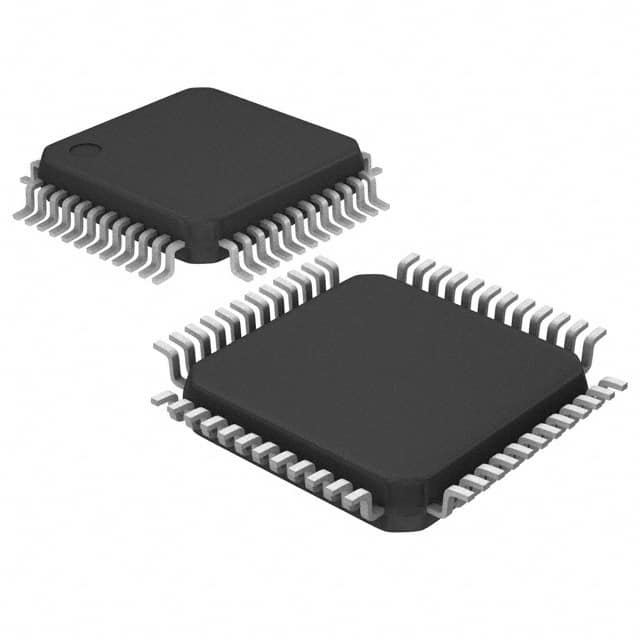
ICGOO在线商城 > 集成电路(IC) > 数据采集 - 模数转换器 > AD9218BSTZ-40
- 型号: AD9218BSTZ-40
- 制造商: Analog
- 库位|库存: xxxx|xxxx
- 要求:
| 数量阶梯 | 香港交货 | 国内含税 |
| +xxxx | $xxxx | ¥xxxx |
查看当月历史价格
查看今年历史价格
AD9218BSTZ-40产品简介:
ICGOO电子元器件商城为您提供AD9218BSTZ-40由Analog设计生产,在icgoo商城现货销售,并且可以通过原厂、代理商等渠道进行代购。 AD9218BSTZ-40价格参考¥76.56-¥81.52。AnalogAD9218BSTZ-40封装/规格:数据采集 - 模数转换器, 10 Bit Analog to Digital Converter 2 Input 2 Pipelined 48-LQFP (7x7)。您可以下载AD9218BSTZ-40参考资料、Datasheet数据手册功能说明书,资料中有AD9218BSTZ-40 详细功能的应用电路图电压和使用方法及教程。
| 参数 | 数值 |
| 产品目录 | 集成电路 (IC)半导体 |
| 描述 | IC ADC 10BIT DUAL 40MSPS 48-LQFP模数转换器 - ADC 10B 40 MSPS 3V Dual |
| 产品分类 | |
| 品牌 | Analog Devices Inc |
| 产品手册 | |
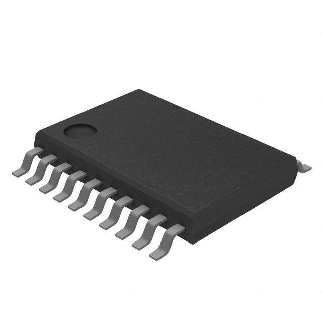
| 产品图片 |
|
| rohs | 符合RoHS无铅 / 符合限制有害物质指令(RoHS)规范要求 |
| 产品系列 | 数据转换器IC,模数转换器 - ADC,Analog Devices AD9218BSTZ-40- |
| 数据手册 | |
| 产品型号 | AD9218BSTZ-40 |
| 产品目录页面 | |
| 产品种类 | 模数转换器 - ADC |
| 位数 | 10 |
| 供应商器件封装 | 48-LQFP(7x7) |
| 信噪比 | 59 dB |
| 其它名称 | AD9218BSTZ40 |
| 分辨率 | 10 bit |
| 包装 | 托盘 |
| 商标 | Analog Devices |
| 安装类型 | 表面贴装 |
| 安装风格 | SMD/SMT |
| 封装 | Tray |
| 封装/外壳 | 48-LQFP |
| 封装/箱体 | LQFP-48 |
| 工作温度 | -40°C ~ 85°C |
| 工作电源电压 | 3.3 V |
| 工厂包装数量 | 250 |
| 接口类型 | Parallel |
| 数据接口 | 并联 |
| 最大功率耗散 | 565 mW |
| 最大工作温度 | + 85 C |
| 最小工作温度 | - 40 C |
| 标准包装 | 1 |
| 特性 | 同步采样 |
| 电压参考 | Internal, External |
| 电压源 | 模拟和数字 |
| 系列 | AD9218 |
| 结构 | Pipeline |
| 转换器数 | 2 |
| 转换器数量 | 2 |
| 转换速率 | 80 MS/s |
| 输入数和类型 | 2 个差分,单极 |
| 输入类型 | Differential |
| 通道数量 | 2 Channel |
| 采样率(每秒) | 40M |







- 商务部:美国ITC正式对集成电路等产品启动337调查
- 曝三星4nm工艺存在良率问题 高通将骁龙8 Gen1或转产台积电
- 太阳诱电将投资9.5亿元在常州建新厂生产MLCC 预计2023年完工
- 英特尔发布欧洲新工厂建设计划 深化IDM 2.0 战略
- 台积电先进制程称霸业界 有大客户加持明年业绩稳了
- 达到5530亿美元!SIA预计今年全球半导体销售额将创下新高
- 英特尔拟将自动驾驶子公司Mobileye上市 估值或超500亿美元
- 三星加码芯片和SET,合并消费电子和移动部门,撤换高东真等 CEO
- 三星电子宣布重大人事变动 还合并消费电子和移动部门
- 海关总署:前11个月进口集成电路产品价值2.52万亿元 增长14.8%



PDF Datasheet 数据手册内容提取
10-Bit, 105 MSPS, 3 V, Dual ADC Enhanced Product AD9218-EP FEATURES GENERAL DESCRIPTION Dual, 10-bit, 105 MSPS ADC The AD9218-EP is a dual, 10-bit, monolithic sampling analog- Low power: 275 mW at 105 MSPS per channel to-digital converter (ADC) with on-chip track-and-hold On-chip reference and track-and-hold circuits. The product is low cost, low power, and is small and 300 MHz analog bandwidth for each channel easy to use. The AD9218-EP operates at a 105 MSPS conversion SNR = 54 dB at 51 MHz, encode = 105 MSPS rate with dynamic performance over its full operating range. 1 V p-p analog input range for each channel Each channel can be operated independently. 3.0 V single-supply operation (2.7 V to 3.6 V) The ADC requires only a single 3.0 V (2.7 V to 3.6 V) power Power-down mode for single-channel operation supply and a clock for full operation. No external reference or Twos complement or offset binary output mode driver components are required for many applications. The Output data alignment mode digital outputs are transistor-to-transistor logic (TTL)/ –75 dBc crosstalk between channels complementary metal-oxide semiconductor (CMOS) ENHANCED PRODUCT FEATURES compatible, and a separate output power supply pin supports interfacing with 3.3 V or 2.5 V logic. Supports defense and aerospace applications (AQEC standard) The clock input is TTL/CMOS compatible and the 10-bit digital Extended industrial temperature range: −55°C to +105°C outputs can be operated from a 3.0 V (2.5 V to 3.6 V) supply. Controlled manufacturing baseline User-selectable options offer a combination of power-down 1 assembly/test site modes, digital data formats, and digital data timing schemes. 1 fabrication site In power-down mode, the digital outputs are driven to a high Product change notification impedance state. Qualification data available on request The AD9218-EP is fabricated on an advanced CMOS process APPLICATIONS and is available in a 48-lead, 7 mm × 7 mm, low profile quad flat package (LQFP), and is specified over the extended Radar industrial temperature range of −55°C to +105°C. Avionics Unmanned systems Additional application and technical information can be found Military communications in the AD9218 data sheet. Missiles and munitions FUNCTIONAL BLOCK DIAGRAM ENCA TIMING AD9218-EP AINA OUTPUT T/H ADC / REGISTER / D9ATO D0A AINA 10 10 S1 REFINA REFOUT REF S2 REFINB DFS/GAIN AAIINNBB T/H ADC 1/0 ROEUGTISPTUETR1/0 D9BTO D0B ENCB TIMING VD GND VDD 17309-001 Figure 1. Rev. 0 Document Feedback Information furnished by Analog Devices is believed to be accurate and reliable. However, no responsibility is assumed by Analog Devices for its use, nor for any infringements of patents or other One Technology Way, P.O. Box 9106, Norwood, MA 02062-9106, U.S.A. rights of third parties that may result from its use. Specifications subject to change without notice. No license is granted by implication or otherwise under any patent or patent rights of Analog Devices. Tel: 781.329.4700 ©2018 Analog Devices, Inc. All rights reserved. Trademarks and registered trademarks are the property of their respective owners. Technical Support www.analog.com
AD9218-EP Enhanced Product TABLE OF CONTENTS Features .............................................................................................. 1 Switching Specifications ...............................................................6 Enhanced Product Features ............................................................ 1 Timing Diagrams ..........................................................................6 Applications ....................................................................................... 1 Absolute Maximum Ratings ............................................................8 General Description ......................................................................... 1 Explanation of Test Levels ............................................................8 Functional Block Diagram .............................................................. 1 Thermal Resistance .......................................................................8 Revision History ............................................................................... 2 ESD Caution...................................................................................8 Specifications ..................................................................................... 3 Pin Configuration and Function Descriptions ..............................9 DC Specifications ......................................................................... 3 Typical Performance Characteristics ........................................... 10 Digital Specifications ................................................................... 4 Outline Dimensions ....................................................................... 11 AC Specifications .......................................................................... 5 Ordering Guide .......................................................................... 11 REVISION HISTORY 12/2018—Revision 0: Initial Version Rev. 0 | Page 2 of 11
Enhanced Product AD9218-EP SPECIFICATIONS DC SPECIFICATIONS V = 3.0 V, V = 3.0 V; external reference, unless otherwise noted. DD D Table 1. Parameter Temperature Test Level Min Typ Max Unit RESOLUTION 10 Bits ACCURACY No Missing Codes1 Full VI Guaranteed, not tested Offset Error2 25°C I –18 +2 +18 LSB Gain Error2 25°C I –2 +3.5 +8 % FS Differential Nonlinearity 25°C I –1 ±0.8 +1.7 LSB (DNL) Full VI ±0.9 LSB Integral Nonlinearity (INL) 25°C I –2.7 ±2 +2.7 LSB Full VI ±2.3 LSB TEMPERATURE DRIFT Offset Error Full V 4 ppm/°C Gain Error2 Full V 100 ppm/°C Reference Full V 40 ppm/°C REFERENCE Internal Reference Voltage 25°C I 1.18 1.24 1.28 V (REF ) OUT Input Resistance (REF A, REF B) Full VI 9 11 13 kΩ IN IN ANALOG INPUTS Differential Input Voltage Range (A x A x)3 Full V 1 V IN , IN Common-Mode Voltage3 Full V V /3 V D Input Resistance Full VI 7 10 16 kΩ Input Capacitance 25°C V 3 pF POWER SUPPLY V Full IV 2.7 3 3.6 V D V Full IV 2.5 3 3.6 V DD Supply Currents IV (V = 3.0 V)4 Full VI 183 188 mA D D IV (V = 3.0 V)4 25°C V 17 mA DD DD Power Dissipation DC5 Full VI 550 565 mW IV Power-Down Current6 Full VI 22 mA D Power Supply Rejection Ratio 25°C I ±1 mV/V 1 No missing codes at room temperature guaranteed. 2 Gain error and gain temperature coefficients are based on the ADC only (with a fixed 1.25 V external reference) in 1 V p-p range. 3 (AINx – AINx) = ±0.5 V in 1 V range (full-scale). The analog inputs self-bias to VD/3. This common-mode voltage can be overdriven externally by a low impedance source by ±300 mV (differential drive, gain = 1). 4 AC power dissipation measured with rated encode and a 10 MHz analog input at 0.5 dBFS, CLOAD = 5 pF. 5 DC power dissipation measured with rated encode and a dc analog input (outputs static, IVDD = 0). 6 In power-down state, IVDD = ±10 µA typical. Rev. 0 | Page 3 of 11
AD9218-EP Enhanced Product DIGITAL SPECIFICATIONS V = 3.0 V, V = 3.0 V; external reference, unless otherwise noted. DD D Table 2. Parameter Temperature Test Level Min Typ Max Unit DIGITAL INPUTS Encode Input Common Mode Full V V /2 V D Encode 1 Voltage Full VI 2 V Encode 0 Voltage Full VI 0.8 V Encode Input Resistance Full VI 1.75 2.0 2.4 kΩ Logic 1 Voltage—S1, S2, DFS Full VI 2 V Logic 0 Voltage—S1, S2, DFS Full VI 0.8 V Logic 1 Current—S1 Full VI –50 ±0 50 µA Logic 0 Current—S1 Full VI –400 –230 –50 µA Logic 1 Current—S2 Full VI 50 230 400 µA Logic 0 Current—S2 Full VI –50 ±0 50 µA Logic 1 Current—DFS Full VI 30 100 200 µA Logic 0 Current—DFS Full VI –400 –230 –50 µA Input Capacitance—S1, S2, Encode Inputs 25°C V 2 pF Input Capacitance DFS 25°C V 4.5 pF DIGITAL OUTPUTS Logic 1 Voltage Full VI 2.45 V Logic 0 Voltage Full VI 0.05 V Output Coding Twos complement or offset binary Rev. 0 | Page 4 of 11
Enhanced Product AD9218-EP AC SPECIFICATIONS V = 3.0 V, V = 3.0 V; external reference, unless otherwise noted. DD D Table 3. Parameter Temperature Test Level Min Typ Max Unit DYNAMIC PERFORMANCE1 Signal-to-Noise Ratio (SNR) (Without Harmonics) f = 10 MHz 25°C I 53 55 dB IN f = Nyquist2 25°C I 52 54 dB IN Signal-to-Noise and Distortion (SINAD) (With Harmonics) f = 10 MHz 25°C I 52 53 dB IN f = Nyquist2 25°C I 51 53 dB IN Effective Number of Bits f = 10 MHz 25°C I 8.4 8.6 Bits IN f = Nyquist2 25°C I 8.3 8.6 Bits IN Second Harmonic Distortion f = 10 MHz 25°C I –60 –68 dBc IN f = Nyquist2 25°C I –57 –66 dBc IN Third Harmonic Distortion f = 10 MHz 25°C I –57 –63 dBc IN f = Nyquist2 25°C I –57 –69 dBc IN Spurious Free Dynamic Range (SFDR) f = 10 MHz 25°C I –57 –62 dBc IN f = Nyquist2 25°C I –57 –63 dBc IN Two-Tone Intermodulation Distortion (IMD) f = 30 MHz, f = 31 MHz at –7 dBFS 25°C V –67 dBc IN1 IN2 Analog Bandwidth, Full Power 25°C V 300 MHz Crosstalk 25°C V –75 dBc 1 AC specifications based on an analog input voltage of –0.5 dBFS at 10.0 MHz, unless otherwise noted. AC specifications are tested in 1 V p-p range and driven differentially. 2 Tested close to Nyquist: 51 MHz. Rev. 0 | Page 5 of 11
AD9218-EP Enhanced Product SWITCHING SPECIFICATIONS V = 3.0 V, V = 3.0 V; external reference, unless otherwise noted. DD D Table 4. Parameter Temperature Test Level Min Typ Max Unit ENCODE INPUT PARAMETERS Maximum Encode Rate Full VI 105 MSPS Minimum Encode Rate Full IV 20 MSPS Encode Pulse Width High (t ) Full IV 3.8 ns EH Encode Pulse Width Low (t ) Full IV 3.8 ns EL Aperture Delay (t ) 25°C V 2 ns A Aperture Uncertainty (Jitter) 25°C V 3 ps rms DIGITAL OUTPUT PARAMETERS Output Valid Time (t )1 Full VI 2.5 ns V Output Propagation Delay (t )1 Full VI 4.5 6 ns PD Output Rise Time (t) 25°C V 1.0 ns R Output Fall Time (t) 25°C V 1.2 ns F Out-of-Range Recovery Time 25°C V 5 ns Transient Response Time 25°C V 5 ns Recovery Time from Power-Down 25°C V 10 Cycles Pipeline Delay Full IV 5 Cycles 1 tV and tPD are measured from the 1.5 level of the ENCx input to the 50%/50% levels of the digital outputs swing. The digital output load during test must not exceed an ac load of 5 pF or a dc current of ±40 µA. Rise and fall times are measured from 10% to 90%. TIMING DIAGRAMS SAMPLE N SAMPLE SAMPLE SAMPLE N + 1 N + 5 N + 6 AINA AINB SAMPLE SAMPLE SAMPLE tA N + 2 N + 3 N + 4 tEL tEH 1/fS ENCA ENCB tPD tV D9ATO D0A DATA N – 5 DATA N – 4 DATA N – 3 DATA N – 2 DATA N – 1 DATA N D9BTO D0B DATA N – 5 DATA N – 4 DATA N – 3 DATA N – 2 DATA N – 1 DATA N 17309-002 Figure 2. Normal Operation, Same Clock (S1 = 1, S2 = 0) Channel Timing Rev. 0 | Page 6 of 11
Enhanced Product AD9218-EP SAMPLE SAMPLE SAMPLE N N + 1 N + 2 SANM +P 7LE SAMPLE N + 8 AINA AINB tA tEL SANM +P 3LE SANM +P 4LE SANM +P 5LESANM +P 6LE tEH 1/fS ENCA tPD tV ENCB D9ATO D0A DATA N – 10 DATA N – 8 DATA N – 6 DATA N – 4 DATA N – 2 DATA N DATA N + 2 D9BTO D0B DATA N – 9 DATA N – 7 DATA N – 5 DATA N – 3 DATA N – 1 DATA N + 1 17309-003 Figure 3. Normal Operation with Two Clock Sources (S1 = 1, S2 = 0) Channel Timing SAMPLE SAMPLE SAMPLE N N + 1 N + 2 SANM +P 7LE SAMPLE N + 8 AINA AINB tA tEL SANM +P 3LE SANM +P 4LE SANM +P 5LESANM +P 6LE tEH 1/fS ENCA tPD tV ENCB D9ATO D0A DATA N – 10 DATA N – 8 DATA N – 6 DATA N – 4 DATA N – 2 DATA N DATA N + 2 D9BTO D0B DATA N –11 DATA N – 9 DATA N – 7 DATA N – 5 DATA N – 3 DATA N – 1 DATA N + 1 17309-004 Figure 4. Data Align with Two Clock Sources (S1 = 1, S2 = 1) Channel Timing Rev. 0 | Page 7 of 11
AD9218-EP Enhanced Product ABSOLUTE MAXIMUM RATINGS Table 5. THERMAL RESISTANCE Parameter Rating Thermal performance is directly linked to printed circuit board VD, VDD 4 V (PCB) design and operating environment. Careful attention to Analog Inputs –0.5 V to VD + 0.5 V PCB thermal design is required. Digital Inputs –0.5 V to V + 0.5 V DD θ is the natural convection, junction to ambient thermal REF Inputs –0.5 V to V + 0.5 V JA IN D resistance measured in a one cubic foot sealed enclosure. Digital Output Current 20 mA Operating Temperature Range –55°C to +105°C θJC is the junction to case thermal resistance. Storage Temperature Range –65°C to +150°C Table 6. Thermal Resistance Junction Temperature 150°C Package Type θ θ Unit Operating 115°C JA JC ST-481 73 12 °C/W Case Temperature 150°C Operating 105°C 1 Thermal impedance simulated values are based on JEDEC 2S2P thermal test board. See JEDEC JESD-51. Stresses at or above those listed under Absolute Maximum Ratings may cause permanent damage to the product. This is a ESD CAUTION stress rating only; functional operation of the product at these or any other conditions above those indicated in the operational section of this specification is not implied. Operation beyond the maximum operating conditions for extended periods may affect product reliability. EXPLANATION OF TEST LEVELS Test Level Description I 100% production tested. II 100% production tested at 25°C and sample tested at specified temperatures. III Sample tested only. IV Parameter is guaranteed by design and characterization testing. V Parameter is a typical value only. VI 100% production tested at 25°C; guaranteed by design and characterization testing for extended industrial temperature range. Rev. 0 | Page 8 of 11
Enhanced Product AD9218-EP PIN CONFIGURATION AND FUNCTION DESCRIPTIONS B) S M VDENCAVDDGND (D9AD8AD7AD6AD5AD4AD3AD2A 48 47 46 45 44 43 42 41 40 39 38 37 GND 1 36 D1A AINA 2 35 D0A AINA 3 34 GND DFS/GAIN 4 33 VDD REFINA 5 AD9218-EP 32 GND REFOUT 6 TOP VIEW 31 VD REFINB 7 (Not to Scale) 30 VD S1 8 29 GND S2 9 28 VDD AINB 10 27 GND AINB 11 26 D0B GND 12 25 D1B 13 14 15 16 17 18 19 20 21 22 23 24 D B DD B B B B B B B B VENC VDGN (MSB) D9 D8 D7 D6 D5 D4 D3 D2 17309-005 Figure 5. Pin Configuration Table 7. Pin Function Descriptions Pin Number Mnemonic Description 1, 12, 16, 27, 29, GND Ground. 32, 34, 45 2 A A Analog Input for Channel A. IN 3 A A Analog Input for Channel A (Complementary). IN 4 DFS/GAIN Data Format Select and Analog Input Gain Mode. Low = offset binary output available, 1 V p-p supported; high = twos complement output available, 1 V p-p supported. 5 REF A Reference Voltage Input for Channel A. IN 6 REF Internal Reference Voltage. OUT 7 REF B Reference Voltage Input for Channel B. IN 8 S1 User Select 1. 9 S2 User Select 2. 10 Analog Input for Channel B (Complementary). A B IN 11 A B Analog Input for Channel B. IN 13, 30, 31, 48 V Analog Supply. D 14 ENC Encode B. Clock input for Channel B. B 15, 28, 33, 46 V Digital Supply. DD 17 to 26 D9 to D0 Digital Output for Channel B (D9 = MSB). B B B 35 to 44 D0 to D9 Digital Output for Channel A (D9 = MSB). A A A 47 ENC Encode A. Clock input for Channel A. A Rev. 0 | Page 9 of 11
AD9218-EP Enhanced Product TYPICAL PERFORMANCE CHARACTERISTICS 1.29 68 SNR SINAD 66 SFDR 1.27 V) 64 T VOLTAGE ( 11..2235 D, SFDR (dB) 6602 PU NA 58 OUTF1.21 NR, SI 56 RE S V 54 1.19 52 1.17–55 –35 –15 TE5MPERA25TURE (4°5C) 65 85 105 50–55 –35 –15 TE5MPERA25TURE (4°5C) 65 85 105 17309-037 Figure 6. VREF Output Voltage vs. Temperature (ILOAD = 300 μA) Figure 8. SNR, SINAD, SFDR vs. Temperature, AIN = 10 MHz, 1 V p-p 4.5 4.0 )S f% R (3.5 O R R E N 3.0 AI G 2.5 2.0–55 –35 –15 TE5MPERA25TURE (4°5C) 65 85 105 17309-036 Figure 7. Gain Error vs. Temperature, AIN = 10 MHz, 1 V p-p Rev. 0 | Page 10 of 11
Enhanced Product AD9218-EP OUTLINE DIMENSIONS SIDE VIEW 9.20 0.75 M1.A60X 9.00 SQ 0.60 8.80 0.45 TOP VIEW 48 37 1.00 REF 1 36 SEATING PLANE 7.20 1.45 0.20 7.00 SQ 1.40 0.15 6.80 1.35 0.09 0.15 7° 12 25 0.10 0° 13 24 0.05 0.08 MAX 0.50 0.27 COPLANARITY VIEW A BSC 0.22 VIEW A 0.17 PKG-005430 ROTATED 90° CCW COMPLIANTTO JEDEC STANDARDS MS-026-BBC 01-17-2018-A Figure 9. 48-Lead Low Profile Quad Flat Package [LQFP] (ST-48) Dimensions shown in millimeters ORDERING GUIDE Model1 Temperature Range Package Description Package Option AD9218SSTZ-105-EP –55°C to +105°C 48-Lead Low Profile Quad Flat Pack [LQFP] ST-48 AD9218SSTZ-105EPRL −55°C to +105°C 48-Lead Low Profile Quad Flat Pack [LQFP] ST-48 1 Z = RoHS Compliant Part. ©2018 Analog Devices, Inc. All rights reserved. Trademarks and registered trademarks are the property of their respective owners. D17309-0-12/18(0) Rev. 0 | Page 11 of 11
Mouser Electronics Authorized Distributor Click to View Pricing, Inventory, Delivery & Lifecycle Information: A nalog Devices Inc.: AD9218BSTZ-80 AD9218BSTZ-RL65 AD9218BSTZ-RL105 AD9218BST-105 AD9218BST-RL105 AD9218BSTZ-65 AD9218BSTZ-RL80 AD9218BSTZ-105 AD9218BSTZ-RL40 AD9218BSTZ-40 AD9218SSTZ-105-EP AD9218SSTZ- 105EPRL
 Datasheet下载
