ICGOO在线商城 > 集成电路(IC) > 线性 - 放大器 - 仪表,运算放大器,缓冲器放大器 > AD8270ACPZ-R7
 Datasheet下载
- 型号: AD8270ACPZ-R7
- 制造商: Analog
- 库位|库存: xxxx|xxxx
- 要求:
| 数量阶梯 | 香港交货 | 国内含税 |
| +xxxx | $xxxx | ¥xxxx |
查看当月历史价格
查看今年历史价格
AD8270ACPZ-R7产品简介:
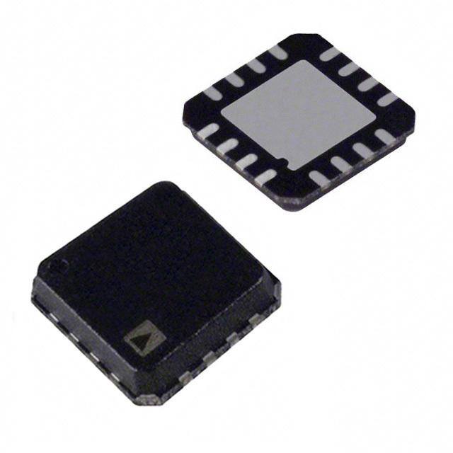
ICGOO电子元器件商城为您提供AD8270ACPZ-R7由Analog设计生产,在icgoo商城现货销售,并且可以通过原厂、代理商等渠道进行代购。 AD8270ACPZ-R7价格参考。AnalogAD8270ACPZ-R7封装/规格:线性 - 放大器 - 仪表,运算放大器,缓冲器放大器, Differential Amplifier 2 Circuit Rail-to-Rail 16-LFCSP-VQ (4x4)。您可以下载AD8270ACPZ-R7参考资料、Datasheet数据手册功能说明书,资料中有AD8270ACPZ-R7 详细功能的应用电路图电压和使用方法及教程。
| 参数 | 数值 |
| -3db带宽 | - |
| 产品目录 | 集成电路 (IC) |
| 描述 | IC OPAMP DIFF 20MHZ RRO 16LFCSP |
| 产品分类 | Linear - Amplifiers - Instrumentation, OP Amps, Buffer Amps |
| 品牌 | Analog Devices Inc |
| 数据手册 | |
| 产品图片 |
|
| 产品型号 | AD8270ACPZ-R7 |
| PCN组件/产地 | |
| rohs | 无铅 / 符合限制有害物质指令(RoHS)规范要求 |
| 产品系列 | - |
| 产品培训模块 | http://www.digikey.cn/PTM/IndividualPTM.page?site=cn&lang=zhs&ptm=25960http://www.digikey.cn/PTM/IndividualPTM.page?site=cn&lang=zhs&ptm=30008http://www.digikey.cn/PTM/IndividualPTM.page?site=cn&lang=zhs&ptm=26202 |
| 供应商器件封装 | 16-LFCSP-VQ (4x4) |
| 其它名称 | AD8270ACPZ-R7DKR |
| 包装 | Digi-Reel® |
| 压摆率 | 30 V/µs |
| 增益带宽积 | 20MHz |
| 安装类型 | 表面贴装 |
| 封装/外壳 | 16-VQFN 裸露焊盘,CSP |
| 工作温度 | -40°C ~ 85°C |
| 放大器类型 | 差分 |
| 标准包装 | 1 |
| 电压-电源,单/双 (±) | 5 V ~ 36 V, ±2.5 V ~ 18 V |
| 电压-输入失调 | 450µV |
| 电流-电源 | 2.3mA |
| 电流-输入偏置 | 500pA |
| 电流-输出/通道 | 100mA |
| 电路数 | 2 |
| 视频文件 | http://www.digikey.cn/classic/video.aspx?PlayerID=1364138032001&width=640&height=505&videoID=2245193153001http://www.digikey.cn/classic/video.aspx?PlayerID=1364138032001&width=640&height=505&videoID=2245193159001 |
| 输出类型 | 满摆幅 |


- 商务部:美国ITC正式对集成电路等产品启动337调查
- 曝三星4nm工艺存在良率问题 高通将骁龙8 Gen1或转产台积电
- 太阳诱电将投资9.5亿元在常州建新厂生产MLCC 预计2023年完工
- 英特尔发布欧洲新工厂建设计划 深化IDM 2.0 战略
- 台积电先进制程称霸业界 有大客户加持明年业绩稳了
- 达到5530亿美元!SIA预计今年全球半导体销售额将创下新高
- 英特尔拟将自动驾驶子公司Mobileye上市 估值或超500亿美元
- 三星加码芯片和SET,合并消费电子和移动部门,撤换高东真等 CEO
- 三星电子宣布重大人事变动 还合并消费电子和移动部门
- 海关总署:前11个月进口集成电路产品价值2.52万亿元 增长14.8%


PDF Datasheet 数据手册内容提取
Precision Dual-Channel Difference Amplifier Data Sheet AD8270 FEATURES FUNCTIONAL BLOCK DIAGRAM WiDthif nfeor eenxcteer anmalp rleifsiiesrt:o grsa ins of 0.5, 1, or 2 +VS OUTA OUTB –VS 6 5 4 3 Single ended amplifiers: over 40 different gains 1 1 1 1 Set reference voltage at midsupply Excellent ac specifications 10kΩ 10kΩ 10kΩ 10kΩ 15 MHz bandwidth –IN1A 1 12 –IN1B 30 V/μs slew rate 10kΩ 10kΩ High accuracy dc performance –IN2A 2 _ _ 11 –IN2B 0.08% maximum gain error 10kΩ 10kΩ +IN2A 3 + + 10 +IN2B 10 ppm/°C maximum gain drift 80 dB minimum CMRR (G = 2) 10kΩ AD8270 10kΩ +IN1A 4 9 +IN1B Two channels in small 4 mm × 4 mm LFCSP Supply current: 2.5 mA per channel 20kΩ 20kΩ 20kΩ 20kΩ Supply range: ±2.5 V to ±18 V 5 6 7 8 APPLICATIONS Instrumentation amplifier building blocks REF1A REF2A REF2B REF1B 06979-001 Level translators Figure 1. Automatic test equipment High performance audio Sine/cosine encoders GENERAL DESCRIPTION The AD8270 operates on both single and dual supplies and requires only 2.5 mA maximum supply current for each ampli- The AD8270 is a low distortion, dual-channel amplifier with fier. It is specified over the industrial temperature range of internal gain setting resistors. With no external components, −40°C to +85°C and is fully RoHS compliant. it can be configured as a high performance difference amplifier with gains of 0.5, 1, or 2. It can also be configured in over 40 single- Table 1. Difference Amplifiers by Category ended configurations, with gains ranging from −2 to +3. High Single-Supply Single-Supply The AD8270 is the first dual-difference amplifier in the small High Speed Voltage Unidirectional Bidirectional 4 mm × 4 mm LFCSP. It requires the same board area as a typical AD8270 AD628 AD8202 AD8205 single-difference amplifier. The smaller package allows a 2× AD8273 AD629 AD8203 AD8206 increase in channel density and a lower cost per channel, all AMP03 AD8216 with no compromise in performance. Rev. A Document Feedback Information furnished by Analog Devices is believed to be accurate and reliable. However, no responsibility is assumed by Analog Devices for its use, nor for any infringements of patents or other One Technology Way, P.O. Box 9106, Norwood, MA 02062-9106, U.S.A. rights of third parties that may result from its use. Specifications subject to change without notice. No license is granted by implication or otherwise under any patent or patent rights of Analog Devices. Tel: 781.329.4700 ©2008–2016 Analog Devices, Inc. All rights reserved. Trademarks and registered trademarks are the property of their respective owners. Technical Support www.analog.com
AD8270 Data Sheet TABLE OF CONTENTS Features .............................................................................................. 1 Circuit Information .................................................................... 13 Applications ....................................................................................... 1 Driving the AD8270 ................................................................... 13 Functional Block Diagram .............................................................. 1 Package Considerations ............................................................. 13 General Description ......................................................................... 1 Power Supplies ............................................................................ 13 Revision History ............................................................................... 2 Input Voltage Range ................................................................... 14 Specifications ..................................................................................... 3 Applications Information .............................................................. 15 Difference Amplifier Configurations ........................................ 3 Difference Amplifier Configurations ...................................... 15 Absolute Maximum Ratings ............................................................ 5 Single-Ended Configurations ................................................... 15 Thermal Resistance ...................................................................... 5 Differential Output .................................................................... 17 Maximum Power Dissipation ..................................................... 5 Driving an ADC ......................................................................... 18 ESD Caution .................................................................................. 5 Driving Cabling .......................................................................... 18 Pin Configuration and Function Descriptions ............................. 6 Outline Dimensions ....................................................................... 19 Typical Performance Characteristics ............................................. 7 Ordering Guide .......................................................................... 19 Theory of Operation ...................................................................... 13 REVISION HISTORY 5/2016—Rev. 0 to Rev. A Changes to Figure 3 and Table 6 ..................................................... 6 Updated Outline Dimensions ....................................................... 19 Changes to Ordering Guide .......................................................... 19 1/2008—Revision 0: Initial Version Rev. A | Page 2 of 20
Data Sheet AD8270 SPECIFICATIONS DIFFERENCE AMPLIFIER CONFIGURATIONS V = ±15 V, V = 0 V, T = 25°C, R = 2 kΩ, specifications referred to input, unless otherwise noted. S REF A LOAD Table 2. Test Conditions/ G = 0.5 G = 1 G = 2 Parameter Comments Min Typ Max Min Typ Max Min Typ Max Unit DYNAMIC PERFORMANCE Bandwidth 20 15 10 MHz Slew Rate 30 30 30 V/µs Settling Time to 0.01% 10 V step on output 700 800 700 800 700 800 ns Settling Time to 0.001% 10 V step on output 750 900 750 900 750 900 ns NOISE/DISTORTION Harmonic Distortion f = 1 kHz, V = 10 V p-p, 84 145 95 dB OUT R = 600 Ω LOAD Voltage Noise1 f = 0.1 Hz to 10 Hz 2 1.5 1 µV p-p f = 1 kHz 52 38 26 nV/√Hz GAIN Gain Error 0.08 0.08 0.08 % Gain Drift T = −40°C to +85°C 1 10 1 10 1 10 ppm/°C A INPUT CHARACTERISTICS Offset2 450 1500 300 1000 225 750 µV Average Temperature Drift T = −40°C to +85°C 3 2 1.5 µV/°C A Common-Mode Rejection DC to 1 kHz 70 86 76 92 80 98 dB Ratio Power Supply Rejection Ratio 2 10 2 10 2 10 µV/V Input Voltage Range3 −15.4 +15.4 −15.4 +15.4 −15.4 +15.4 V Common-Mode Resistance4 7.5 10 7.5 kΩ Bias Current 500 500 500 nA OUTPUT CHARACTERISTICS Output Swing −13.8 +13.8 −13.8 +13.8 −13.8 +13.8 V T = −40°C to +85°C −13.7 +13.7 −13.7 +13.7 −13.7 +13.7 V A Short-Circuit Current Limit Sourcing 100 100 100 mA Sinking 60 60 60 mA POWER SUPPLY Supply Current 2.3 2.5 2.3 2.5 2.3 2.5 mA (per Amplifier) T = −40°C to +85°C 3 3 3 mA A 1 Includes amplifier voltage and current noise, as well as noise of internal resistors. 2 Includes input bias and offset errors. 3 At voltages beyond the rails, internal ESD diodes begin to turn on. In some configurations, the input voltage range may be limited by the internal op amp (see the Input Voltage Range section for details). 4 Internal resistors are trimmed to be ratio matched but have ±20% absolute accuracy. Common-mode resistance was calculated with both inputs in parallel. Common- mode impedance at only one input is 2× the resistance listed. Rev. A | Page 3 of 20
AD8270 Data Sheet V = ±5 V, V = 0 V, T = 25°C, R = 2 kΩ, specifications referred to input, unless otherwise noted. S REF A LOAD Table 3. Test Conditions/ G = 0.5 G = 1 G = 2 Parameter Comments Min Typ Max Min Typ Max Min Typ Max Unit DYNAMIC PERFORMANCE Bandwidth 20 15 10 MHz Slew Rate 30 30 30 V/µs Settling Time to 0.01% 5 V step on output 550 650 550 650 550 650 ns Settling Time to 0.001% 5 V step on output 600 750 600 750 600 750 ns NOISE/DISTORTION Harmonic Distortion f = 1 kHz, V = 5 V p-p, 101 141 112 dB OUT R = 600 Ω LOAD Voltage Noise1 f = 0.1 Hz to 10 Hz 2 1.5 1 µV p-p f = 1 kHz 52 38 26 nV/√Hz GAIN Gain Error 0.08 0.08 0.08 % Gain Drift T = −40°C to +85°C 1 10 1 10 1 10 ppm/°C A INPUT CHARACTERISTICS Offset2 450 1500 300 1000 225 750 µV Average Temperature Drift T = −40°C to +85°C 3 2 1.5 µV/°C A Common-Mode Rejection Ratio DC to 1 kHz 70 86 76 92 80 98 dB Power Supply Rejection Ratio 2 10 2 10 2 10 dB Input Voltage Range3 −5.4 +5.4 −5.4 +5.4 −5.4 +5.4 V Common-Mode Resistance4 7.5 10 7.5 kΩ Bias Current 500 500 500 nA OUTPUT CHARACTERISTICS Output Swing −4 +4 −4 +4 −4 +4 V T = −40°C to +85°C −3.9 +3.9 −3.9 +3.9 −3.9 +3.9 V A Short-Circuit Current Limit Sourcing 100 100 100 mA Sinking 60 60 60 mA POWER SUPPLY Supply Current (per Amplifier) 2.3 2.5 2.3 2.5 2.3 2.5 mA T = −40°C to +85°C 3 3 3 mA A 1 Includes amplifier voltage and current noise, as well as noise of internal resistors. 2 Includes input bias and offset errors. 3 At voltages beyond the rails, internal ESD diodes begin to turn on. In some configurations, the input voltage range may be limited by the internal op amp (see the Input Voltage Range section for details). 4 Internal resistors are trimmed to be ratio matched but have ±20% absolute accuracy. Common-mode resistance was calculated with both inputs in parallel. Common- mode impedance at only one input is 2× the resistance listed. Rev. A | Page 4 of 20
Data Sheet AD8270 ABSOLUTE MAXIMUM RATINGS MAXIMUM POWER DISSIPATION Table 4. The maximum safe power dissipation for the AD8270 is limited Parameter Rating by the associated rise in junction temperature (T) on the die. At Supply Voltage ±18 V J approximately 130°C, which is the glass transition temperature, Output Short-Circuit Current See derating curve in Figure 2 the plastic changes its properties. Even temporarily exceeding this Input Voltage Range ±V temperature limit may change the stresses that the package exerts S Storage Temperature Range −65°C to +130°C on the die, permanently shifting the parametric performance of the Specified Temperature Range −40°C to +85°C amplifiers. Exceeding a temperature of 130°C for an extended Package Glass Transition Temperature (T ) 130°C period of time can result in a loss of functionality. G ESD The AD8270 has built-in, short-circuit protection that limits the Human Body Model 1 kV output current to approximately 100 mA (see Figure 19 for more Charge Device Model 1 kV information). While the short-circuit condition itself does not Machine Model 0.1 kV damage the device, the heat generated by the condition can cause the device to exceed its maximum junction temperature, with Stresses at or above those listed under Absolute Maximum corresponding negative effects on reliability. Ratings may cause permanent damage to the product. This is a stress rating only; functional operation of the product at these 3.2 TJ MAXIMUM = 130°C or any other conditions above those indicated in the operational 2.8 section of this specification is not implied. Operation beyond N (W) the maximum operating conditions for extended periods may O 2.4 TI PAD SOLDERED A affect product reliability. SIP 2.0 θJA = 57°C/W S THERMAL RESISTANCE DI R 1.6 E W Table 5. Thermal Resistance PO 1.2 Thermal Pad θJA Unit MUM 0.8 PAD NOTθ JSAO =L D96E°RCE/WD 16-Lead LFCSP with Thermal Pad 57 °C/W XI A Soldered to Board M 0.4 16-Lead LFCSP with Thermal Pad 96 °C/W Not Soldered to Board 0–50 –25 A0MBIEN2T5 TEMPE5R0ATURE7 5(°C) 100 125 06979-003 The θ values in Table 5 assume a 4-layer JEDEC standard JA Figure 2. Maximum Power Dissipation vs. Ambient Temperature board with zero airflow. If the thermal pad is soldered to the ESD CAUTION board, it is also assumed it is connected to a plane. θ at the JC exposed pad is 9.7°C/W. Rev. A | Page 5 of 20
AD8270 Data Sheet PIN CONFIGURATION AND FUNCTION DESCRIPTIONS A B +VS OUT OUT –VS 6 5 4 3 1 1 1 1 –IN1A 1 12 –IN1B –IN2A 2 AD8270 11 –IN2B +IN2A 3 TOP VIEW 10 +IN2B +IN1A 4 9 +IN1B 5 6 7 8 A A B B 1 2 2 1 F F F F E E E E R R R R N1.O TTIEE STHE EXPOSEDPADTO –VS. 06979-002 Figure 3. Pin Configuration Table 6. Pin Function Descriptions Pin No. Mnemonic Description 1 −IN1A 10 kΩ Resistor Connected to Negative Terminal of Op Amp A. 2 −IN2A 10 kΩ Resistor Connected to Negative Terminal of Op Amp A. 3 +IN2A 10 kΩ Resistor Connected to Positive Terminal of Op Amp A. 4 +IN1A 10 kΩ Resistor Connected to Positive Terminal of Op Amp A. 5 REF1A 20 kΩ Resistor Connected to Positive Terminal of Op Amp A. Most configurations use this pin as a reference voltage input. 6 REF2A 20 kΩ Resistor Connected to Positive Terminal of Op Amp A. Most configurations use this pin as a reference voltage input. 7 REF2B 20 kΩ Resistor Connected to Positive Terminal of Op Amp B. Most configurations use this pin as a reference voltage input. 8 REF1B 20 kΩ Resistor Connected to Positive Terminal of Op Amp B. Most configurations use this pin as a reference voltage input. 9 +IN1B 10 kΩ Resistor Connected to Positive Terminal of Op Amp B. 10 +IN2B 10 kΩ Resistor Connected to Positive Terminal of Op Amp B. 11 −IN2B 10 kΩ Resistor Connected to Negative Terminal of Op Amp B. 12 −IN1B 10 kΩ Resistor Connected to Negative Terminal of Op Amp B. 13 −V Negative Supply. S 14 OUTB Op Amp B Output. 15 OUTA Op Amp A Output. 16 +V Positive Supply. S 0 EPAD Exposed Pad. Tie the exposed pad to −V. S Rev. A | Page 6 of 20
Data Sheet AD8270 TYPICAL PERFORMANCE CHARACTERISTICS V = ±15 V, T = 25°C, difference amplifier configuration, unless otherwise noted. S A 160 20 N: 1043 (0, +15) MEAN: –0.003 140 SD: 0.28 V) 15 E ( (–7.5, +7.5) (+7.5, +7.5) 120 AG 10 T S L NIT100 VO 5 U T F U ER O 80 E INP 0 B D M 60 O –5 U M N N- 40 MMO–10 (–7.5, –7.5) (+7.5, –7.5) O 20 C–15 (0, –15) 0 –0.9 –0.6SYST–E0M.3 OFFSE0T VOLTA0G.3E (mV)0.6 0.9 06979-004 –20–10 –5 OUTPUT VO0LTAGE (V) 5 10 06979-007 Figure 4. Typical Distribution of System Offset Voltage, G = 1 Figure 7. Common-Mode Input Voltage vs. Output Voltage, Gain = 0.5, ±15 V Supplies 6 N: 984 (0, +5) MEAN: –1.01 180 SD: 27 V) 4 E ( (–2.5, +2.5) (+2.5, +2.5) G (0, +2.5) 150 A NITS VOLT 2 (–1.25, –1.25) (+1.25, +1.25) F U120 UT VS = ±2.5 VS = ±5 ER O 90 E INP 0 B D M O NU 60 N-M –2 (–1.25, –1.25) (+1.25, –1.25) MO (0, –2.5) M (–2.5, –2.5) (+2.5, –2.5) 30 CO –4 (0, –5) –0150 –100 –50 CMRR0 (µV/V) 50 100 150 06979-005 –6–3 –2 –O1UTPUT VO0LTAGE (V1) 2 3 06979-008 Figure 5. Typical Distribution of CMRR, G = 1 Figure 8. Common-Mode Input Voltage vs. Output Voltage, Gain = 0.5, ±5 V and ±2.5 V Supplies 400 N: 1043 20 MEAN: –0.015 (0, +15) 350 SD: 0.0068 V) 15 300 AGE ( 10 (–14.3, +7.85) (+14.3, +7.85) S T T L UNI250 VO 5 R OF 200 NPUT 0 BE E I UM150 OD –5 N M N- 100 MMO–10 (–14.3, –7.85) (+14.3, –7.85) 50 CO–15 (0, –15) 0 –0.04 –0.0G2AIN ERRO0R (%) 0.02 0.04 06979-006 –20–20 –15 –10 OU–T5PUT VO0LTAGE5 (V) 10 15 20 06979-009 Figure 6. Typical Distribution of Gain Error, G = 1 Figure 9. Common-Mode Input Voltage vs. Output Voltage, Gain = 1, ±15 V Supplies Rev. A | Page 7 of 20
AD8270 Data Sheet 6 140 (0, +5) GAIN = 2, 0.5 E (V) 4 (–4.3, +2.85) (+4.3, +2.85) 120 G (0, +2.5) OLTA 2 (–1.6, +1.7) (+1.6, +1.7) dB)100 GAIN = 1 ON-MODE INPUT V –20 (–1.6, –1.7) VS = ±2.5 (+1.6V, S– 1=. 7±)5 POSITIVE PSRR ( 864000 M (0, –2.5) COM –4 ((––44..33,, +–22..8855)) (+4.3, –2.85) 20 (0, –5) –6–5 –4 –3 –2OUT–P1UT VO0LTAG1E (V)2 3 4 5 06979-010 010 100 FR1kEQUENCY 1(H0kz) 100k 1M 06979-015 Figure 10. Common-Mode Input Voltage vs. Output Voltage, Figure 13. Positive PSRR vs. Frequency Gain = 1, ±5 V and ±2.5 V Supplies 20 140 (0, +15) V) 15 120 GAIN = 2, 0.5 E ( (–14.3, +11.4) (+14.3, +11.4) LTAG 10 B)100 GAIN = 1 ODE INPUT VO –550 ATIVE PSRR (d 8600 M G MON-–10 NE 40 M (–14.3, –11.4) (+14.3, –11.4) O C–15 20 (0, –15) –20–20 –15 –10 OU–T5PUT VO0LTAGE5 (V) 10 15 20 06979-011 010 100 FR1kEQUENCY 1(H0kz) 100k 1M 06979-016 Figure 11. Common-Mode Input Voltage vs. Output Voltage, Figure 14. Negative PSRR vs. Frequency Gain = 2, ±15 V Supplies 6 32 (0, +5) VS = ±15V LTAGE (V) 42 (–4, +4)(–1.6, +2.1) (0, +2.5) (+1.6, +2.1()+4, +4) G (V p-p) 2284 VO WIN 20 NPUT 0 VS = ±2.5 VS = ±5 GE S 16 E I TA D L O O 12 MON-M –2 (–1.6, –2.1) (0, –2.5) (+1.6, –2.1) TPUT V 8 VS = ±5V M U O –4 O C (–4, –4) (+4, –4) 4 (0, –5) –6–5 –4 –3 –2OUT–P1UT VO0LTAG1E (V)2 3 4 5 06979-012 0100 1k F1R0EkQUENCY1 (0H0zk) 1M 10M 06979-017 Figure 12. Common-Mode Input Voltage vs. Output Voltage, Figure 15. Output Voltage Swing vs. Large Signal Frequency Response Gain = 2, ±5 V and ±2.5 V Supplies Rev. A | Page 8 of 20
Data Sheet AD8270 10 120 ISHORT+ GAIN = 2 100 5 80 A) m 60 GAIN = 1 T ( 0 EN 40 R B) UR 20 GAIN (d –5 GAIN = 0.5 RCUIT C –200 –10 T-CI –40 OR –60 ISHORT– H –15 S –80 –100 –20100 1k 10kFREQU1E0N0kCY (Hz)1M 10M 100M 06979-018 –120–40 –20 0 T2E0MPER4A0TURE6 (0°C) 80 100 120 06979-021 Figure 16. Gain vs. Frequency Figure 19. Short-Circuit Current vs. Temperature 100 +VS +125°C 90 GAIN = 2, 0.5 80 GAIN = 1 V)+VS– 2 –40°C +25°C +85°C G ( 70 N WI+VS– 4 B) 60 E S d G MRR ( 50 OLTA 0 +125°C C 40 V UT –VS+ 2 +85°C 30 P T +25°C U 20 O –VS+ 4 10 –40°C 010 100 1kFREQU1E0NkCY (Hz)100k 1M 10M 06979-019 –VS200 1kRLOAD (Ω) 10k 06979-022 Figure 17. CMRR vs. Frequency Figure 20. Output Voltage Swing vs. RLOAD 0 +VS –40°C CROSSTALK (G = 1) +25°C –20 +VS – 3 ON (dB) –40 WING (V)+VS – 6 ATI –60 E S +125°C +85°C R G EPA LTA 0 S –80 O L V HANNE–100 UTPUT –VS + 6 +125°C +85°C C O +25°C –120 –VS + 3 –40°C –14010 100 FREQUE1NkCY (Hz) 10k 100k 06979-013 –VS0 20 C4U0RRENT (m6A0) 80 100 06979-023 Figure 18. Channel Separation vs. Frequency Figure 21. Output Voltage Swing vs. Current (IOUT) Rev. A | Page 9 of 20
AD8270 Data Sheet 160 VS = ±15V 140 0pF 18pF100pF 120 VS = ±5V VS = ±10V VS = ±2.5V %) 100 DIV OT ( V/ O 80 m H 50 RS VE 60 O 40 VS = ±18V VS = ±15V 20 1µs/DIV 06979-024 00 10 20 30CAPA40CITIV5E0 LOA6D0 (pF)70 80 90 100 06979-030 Figure 22. Small Signal Step Response, Gain = 0.5 Figure 25. Small Signal Overshoot with Capacitive Load, Gain = 0.5 80 VS = ±15V 70 220pF 0pF 33pF 60 VS = ±10V VS = ±5V DIV OT (%) 50 VS = ±2.5V mV/ HO 40 0 S 5 R VE 30 O 20 VS = ±18V VS = ±15V 10 1µs/DIV 06979-025 00 50 CAPACI1T0I0VE LOAD (p1F5)0 200 06979-031 Figure 23. Small Signal Step Response, Gain = 1 Figure 26. Small Signal Overshoot with Capacitive Load, Gain = 1 80 VS = ±15V 70 470pF 0pF100pF 60 %) 50 DIV OT ( VS = ±10V ms/ HO 40 50 RS VS = ±5V VE 30 O VS = ±2.5V 20 VS = ±18V 10 1µs/DIV 06979-026 00 50 100 15C0APA2C0I0TVIVSE =2 L5±0O15AVD3 0(p0F) 350 400 450 06979-032 Figure 24. Small Signal Step Response, Gain = 2 Figure 27. Small Signal Overshoot with Capacitive Load, Gain = 2 Rev. A | Page 10 of 20
Data Sheet AD8270 45 VS = ±15V VIN = ±5V 40 s) 35 +SR µ E (V/ 30 –SR T 1V/DIV LEW RA 2250 S T PU 15 T U O 10 5 1µs/DIV 06979-033 0–45–35–25–15–5 5 1T5EM2P5ER35AT4U5RE55 (°C65) 75 85 95105115125 06979-036 Figure 28. Large Signal Pulse Response Gain = 0.5 Figure 31. Output Slew Rate vs. Temperature 1k VS = ±15V VIN = ±5V Hz) √ V/ GAIN = 2 n DIV SE ( V/ OI 100 2 N E GAIN = 1 G A T L O V 1µs/DIV 06979-034 101 10 GAIFN1R 0=E0 Q0.U5ENCY (1Hkz) 10k 100k 06979-041 Figure 29. Large Signal Pulse Response Gain = 1 Figure 32. Voltage Noise Spectral Density vs. Frequency, Referred to Output VS = ±15V GAIN = 2 VIN = ±5V GAIN = 1 V DI V/ 5 GAIN = 1/2 1µs/DIV 06979-035 1µV/DIV 1s/DIV 06979-042 Figure 30. Large Signal Pulse Response, Gain = 2 Figure 33. 0.1 Hz to 10 Hz Voltage Noise, Referred to Output Rev. A | Page 11 of 20
AD8270 Data Sheet 210 N: 1043 MEAN: 4.6 SD: 134.5 180 UNITS150 V/DIV) OF 120 10µ ER ET ( B 90 S M F U F N O 60 30 0 –600 –400 –200 VOSI0 (µV) 200 400 600 06979-014 0 1 2 3 4 TIM5E (s) 6 7 8 9 10 06979-044 Figure 34. Typical Distribution of Op Amp Voltage Offset Figure 37. Change in Op Amp Offset Voltage vs. Warm-Up Time 100 N: 1043 MEAN: 321.6 SD: 6.9 80 S T NI U 60 F O R E B M 40 U N 20 0 310 315 320 IB3IA2S5 (nA)330 335 340 06979-020 50pA/DIV 1s/DIV 06979-028 Figure 35. Typical Distribution of Op Amp Bias Current Figure 38. 0.1 Hz to 10 Hz Current Noise of Internal Op Amp 10 160 N: 1043 MEAN: 0.31 SD: 2.59 140 BER OF UNITS11208000 T NOISE (pA/√Hz) 1 M N U 60 E N R R U 40 C 20 0–9 –6 –3 IO0FFSET (n3A) 6 9 12 06979-027 0.11 10 F1R0E0QUENCY (1Hkz) 10k 100k 06979-029 Figure 36. Typical Distribution of Op Amp Offset Current Figure 39. Current Noise Spectral Density of Internal Op Amp Rev. A | Page 12 of 20
Data Sheet AD8270 THEORY OF OPERATION A B Size +VS OUT OUT –VS The AD8270 fits two op amps and 14 resistors in a 4 mm × 6 5 4 3 1 1 1 1 4 mm package. DRIVING THE AD8270 –IN1A 1 10kΩ 10kΩ 10kΩ 10kΩ 12 –IN1B The AD8270 is easy to drive, with all configurations presenting at least several kilohms (kΩ) of input resistance. The AD8270 10kΩ 10kΩ –IN2A 2 _ _ 11 –IN2B should be driven with a low impedance source: for example, 10kΩ 10kΩ another amplifier. The gain accuracy and common-mode rejection +IN2A 3 + 10 +IN2B of the AD8270 depend on the matching of its resistors. Even AD8270 10kΩ 10kΩ source resistance of a few ohms can have a substantial effect on +IN1A 4 9 +IN1B these specifications. 20kΩ 20kΩ 20kΩ 20kΩ PACKAGE CONSIDERATIONS 5 6 7 8 The AD8270 is packaged in a 4 mm × 4 mm LFCSP. Beware of REF1A REF2A REF2B REF1B 06979-059 bdleivnidcley; cito mpyaiyn gn otht eh faovoet pthrien st afmroem t haenromthaelr p 4a dm smiz e× a 4n md mlea LdFs.C SP Figure 40. Functional Block Diagram Refer to the Outline Dimensions section to verify that the PCB CIRCUIT INFORMATION symbol has the correct dimensions. The AD8270 has two channels, each consisting of a high The 4 mm × 4 mm LFCSP of the AD8270 comes with a thermal precision, low distortion op amp and seven trimmed resistors. pad. This pad is connected internally to −VS. Connecting to this These resistors can be connected to make a wide variety of pad is not necessary for electrical performance; the pad can be amplifier configurations: difference, noninverting, inverting, left unconnected or can be connected to the negative supply rail. and more. The resistors on the chip can be connected in parallel Connecting the pad to the negative supply rail is recommended for a wider range of options. Using the on-chip resistors of the in high vibration applications or when good heat dissipation is AD8270 provides the designer several advantages over a required (for example, with high ambient temperatures or when discrete design. driving heavy loads). For best heat dissipation performance, the DC Performance negative supply rail should be a plane in the board. See the Absolute Maximum Ratings section for thermal coefficients with and Much of the dc performance of op amp circuits depends on the without the pad soldered. accuracy of the surrounding resistors. The resistors on the AD8270 are laid out to be tightly matched. The resistors of each device are Space between the leads and thermal pad should be as wide as laser trimmed and tested for their matching accuracy. Because of possible to minimize the risk of contaminants affecting perform- this trimming and testing, the AD8270 can guarantee high ance. A thorough washing of the board is recommended after the accuracy for specifications such as gain drift, common-mode soldering process, especially if high accuracy performance is rejection, and gain error. required at high temperatures. AC Performance POWER SUPPLIES Because feature size is much smaller in an integrated circuit than A stable dc voltage should be used to power the AD8270. Noise on a printed circuit board (PCB), the corresponding parasitics are on the supply pins can adversely affect performance. A bypass smaller, as well. The smaller feature size helps the ac performance capacitor of 0.1 μF should be placed between each supply pin of the AD8270. For example, the positive and negative input and ground, as close as possible to each supply pin. A tantalum terminals of the AD8270 op amp are not pinned out intentionally. capacitor of 10 μF should also be used between each supply and By not connecting these nodes to the traces on the PCB, the ground. It can be farther away from the supply pins and, typically, capacitance remains low, resulting in both improved loop it can be shared by other precision integrated circuits. stability and common-mode rejection over frequency. The AD8270 is specified at ±15 V and ±5 V, but it can be used with Production Costs unbalanced supplies, as well. For example, −V = 0 V, +V = 20 V. S S The difference between the two supplies must be kept below 36 V. Because one part, rather than several, is placed on the PCB, the board can be built more quickly. Rev. A | Page 13 of 20
AD8270 Data Sheet INPUT VOLTAGE RANGE The internal op amp voltage range may be relevant in the following applications, and calculating the voltage at the The AD8270 has a true rail-to-rail input range for the majority internal op amp is advised. of applications. Because most AD8270 configurations divide down the voltage before they reach the internal op amp, the op amp sees Difference amplifier configurations using supply voltages only a fraction of the input voltage. Figure 41 shows an example of less than ±4.5 V of how the voltage division works in the difference amplifier Difference amplifier configurations with a reference configuration. voltage near the rail R1R +2 R2(V+IN) Single-ended amplifier configurations R4 For correct operation, the input voltages at the internal op amp R3 must stay within 1.5 V of either supply rail. R1 Voltages beyond the supply rails should not be applied to the R2 device. The device contains ESD diodes at the input pins, which R1R +2 R2(V+IN) 06979-061 cthoannd u5c mt iAf v coaltna gdeasm baegyeo nthde tshe ed rioaidlse sa raen adp tphleie dde. vCicuer.r eFnotrs ag sriematielra r Figure 41. Voltage Division in the Difference Amplifier Configuration device that can operate with voltages beyond the rails, see the AD8273 data sheet. Rev. A | Page 14 of 20
Data Sheet AD8270 APPLICATIONS INFORMATION DIFFERENCE AMPLIFIER CONFIGURATIONS SINGLE-ENDED CONFIGURATIONS The AD8270 can be placed in difference amplifier configurations The AD8270 can be configured for a wide variety of single-ended with gains of 0.5, 1, and 2. Figure 42 through Figure 44 show the configurations with gains ranging from −2 to +3. Table 8 shows difference amplifier configurations, referenced to ground. The a subset of the possible configurations. AD8270 can also be referred to a combination of reference Many signal gains have more than one configuration choice, voltages. For example, the reference could be set at 2.5 V, which allows freedom in choosing the op amp closed-loop gain. using just 5 V and GND. Some of the possible configurations In general, for designs that need to be stable with a large capacitive are shown in Figure 45 through Figure 47. load on the output, choose a configuration with high loop gain. The layout for Channel A is shown in Figure 42 through Figure 47. Otherwise, choose a configuration with low loop gain, because The layout for Channel B is symmetrical. Table 7 shows the pin these configurations typically have lower noise, lower offset, connections for Channel A and Channel B. and higher bandwidth. 16 15 5kΩ 16 15 5kΩ +–IINN 2134 11110000kkkk2ΩΩΩΩ0kΩ1200kkΩΩ = +–IINN 1100kkΩΩ 5kΩ +–IINN 1234 11110000kkkk2ΩΩΩΩ0kΩ1200kkΩΩ = +–IINN 1100kkΩΩ 5kΩ 5GND6 GND 06979-053 –VS 5+VS6 +VS 2+ –VS 06979-056 Figure 42. Gain = 0.5 Difference Amplifier, Referenced to Ground Figure 45. Gain = 0.5 Difference Amplifier, Referenced to Midsupply 16 15 10kΩ 16 15 10kΩ –IN 1 10kΩ 10kΩ 10kΩ –IN 1 10kΩ 10kΩ 10kΩ NC 2 10kΩ –IN NC 2 10kΩ –IN NC 3 10kΩ = +IN 10kΩ NC 3 10kΩ = +IN 10kΩ +IN 4 10kΩ +IN 4 10kΩ 20kΩ 20kΩ 10kΩ 20kΩ 20kΩ 10kΩ 5 6 5 6 GND +VS + –VS NC = NO CONGNNEDCT 06979-054 NC = NO CO–NVNSE+CVTS 2 06979-057 Figure 43. Gain = 1 Difference Amplifier, Referenced to Ground Figure 46. Gain = 1 Difference Amplifier, Referenced to Midsupply 16 15 10kΩ 16 15 10kΩ 10kΩ 10kΩ 10kΩ 10kΩ 1 5kΩ 1 5kΩ –IN 10kΩ –IN –IN 10kΩ –IN 2 2 3 10kΩ = +IN 5kΩ 3 10kΩ = +IN 5kΩ +IN 4 10kΩ +IN 4 10kΩ 20kΩ 20kΩ 10kΩ 20kΩ 20kΩ 10kΩ 5GND6 GND 06979-055 –V5S+V6S +VS 2+ –VS 06979-058 Figure 44. Gain = 2 Difference Amplifier, Referenced to Ground Figure 47. Gain = 2 Difference Amplifier, Referenced to Midsupply Table 7. Pin Connections for Difference Amplifier Configurations Channel A Channel B Gain and Reference Pin 1 Pin 2 Pin 3 Pin 4 Pin 5 Pin 6 Pin 12 Pin 11 Pin 10 Pin 9 Pin 8 Pin 7 Gain of 0.5, Referenced to Ground OUT −IN +IN GND GND GND OUT −IN +IN GND GND GND Gain of 0.5, Referenced to Midsupply OUT −IN +IN −V +V +V OUT −IN +IN −V +V +V S S S S S S Gain of 1, Referenced to Ground −IN NC NC +IN GND GND −IN NC NC +IN GND GND Gain of 1, Referenced to Midsupply −IN NC NC +IN −V +V −IN NC NC +IN −V +V S S S S Gain of 2, Referenced to Ground −IN −IN +IN +IN GND GND −IN −IN +IN +IN GND GND Gain of 2, Referenced to Midsupply −IN −IN +IN +IN −V +V −IN −IN +IN +IN −V +V S S S S Rev. A | Page 15 of 20
AD8270 Data Sheet Table 8. Selected Single-Ended Configurations Electrical Performance Pin Connections Op Amp Input 10 kΩ − 10 kΩ − 10 kΩ + 10 kΩ + 20 kΩ + 20 kΩ + Signal Gain Closed-Loop Gain Resistance Pin 1 Pin 2 Pin 3 Pin 4 Pin 5 Pin 6 −2 3 5 kΩ IN IN GND GND GND GND −1.5 3 4.8 kΩ IN IN GND GND GND IN −1.4 3 5 kΩ IN IN GND GND NC IN −1.25 3 5.333 kΩ IN IN GND NC GND IN −1 3 5 kΩ IN IN GND GND IN IN −0.8 3 5.556 kΩ IN IN IN GND NC GND −0.667 2 8 kΩ IN NC GND GND GND IN −0.6 2 8.333 kΩ IN NC GND GND NC IN −0.5 2 8.889 kΩ IN NC GND NC GND IN −0.333 2 7.5 kΩ IN NC GND GND IN IN −0.25 1.5 8 kΩ OUT IN GND GND GND IN −0.2 1.5 8.333 kΩ OUT IN GND GND NC IN −0.125 1.5 8.889 kΩ OUT IN GND NC GND IN +0.1 1.5 8.333 kΩ OUT IN IN GND NC GND +0.2 2 10 kΩ IN NC GND IN NC IN +0.25 1.5 24 kΩ OUT GND GND GND GND IN +0.3 1.5 25 kΩ OUT GND GND GND NC IN +0.333 2 24 kΩ GND NC GND GND GND IN +0.375 1.5 26.67 kΩ OUT GND GND NC GND IN +0.4 2 25 kΩ GND NC GND GND NC IN +0.5 3 24 kΩ GND GND GND GND GND IN +0.5 1.5 15 kΩ OUT GND GND GND IN IN +0.6 3 25 kΩ GND GND GND GND NC IN +0.6 1.5 16.67 kΩ OUT GND IN GND NC GND +0.625 1.5 16 kΩ OUT IN NC IN IN GND +0.667 2 15 kΩ GND NC GND GND IN IN +0.7 1.5 16.67 kΩ OUT IN IN IN NC GND +0.75 3 26.67 kΩ GND GND GND NC GND IN +0.75 1.5 13.33 kΩ OUT GND GND IN GND IN +0.8 2 16.67 kΩ GND NC IN GND NC GND +0.9 1.5 16.67 kΩ OUT GND GND IN NC IN +1 1.5 15 kΩ OUT GND IN IN GND GND +1 1.5 >1 GΩ OUT IN IN IN IN IN +1 3 >1 GΩ IN IN IN IN IN IN +1.125 1.5 26.67 kΩ OUT GND NC IN IN GND +1.2 3 16.67 kΩ GND GND IN GND NC GND +1.2 1.5 25 kΩ OUT GND IN IN NC GND +1.25 1.5 24 kΩ OUT GND IN IN IN GND +1.333 2 15 kΩ GND NC IN IN GND GND +1.5 3 13.33 kΩ GND GND GND IN GND IN +1.5 1.5 >1 GΩ OUT GND IN IN IN IN +1.6 2 25 kΩ GND NC IN IN NC GND +1.667 2 24 kΩ GND NC IN IN IN GND +1.8 3 16.67 kΩ GND GND GND IN NC IN +2 2 >1 GΩ GND NC IN IN IN IN +2.25 3 26.67 kΩ GND GND NC IN IN GND +2.4 3 25 kΩ GND GND IN IN NC GND +2.5 3 24 kΩ GND GND IN IN IN GND +3 3 >1 GΩ GND GND IN IN IN IN Rev. A | Page 16 of 20
Data Sheet AD8270 The AD8270 Specifications section and Typical Performance +OUT –OUT Characteristics section show the performance of the device 16 15 14 13 V+IN – V–IN = V+OUT – V–OUT primarily when it is in the difference amplifier configuration. To VOCM = V+OUT + V–OUT get a good estimate of the performance of the device in a single- 1 10kΩ 10kΩ 10kΩ 10kΩ12 ended configuration, refer to the difference amplifier configuration –IN 2 10kΩ _ _ 10kΩ11 +IN +IN +OUT with the corresponding closed-loop gain (see Table 9). +IN 3 10kΩ + + 10kΩ10 –IN = VOCM 4 10kΩ AD8270 10kΩ9 –IN –OUT Table 9. Closed-Loop Gain of the Difference Amplifiers 20kΩ20kΩ 20kΩ20kΩ Difference Amplifier Gain Closed-Loop Gain 5 6 7 8 01. 5 21 .5 OCM OCM 06979-062 2 3 Figure 48. Differential Output, G = 1, Common-Mode Output Voltage Set with Reference Voltage Gain of 1 Configuration +OUT –OUT The AD8270 is designed to be stable for loop gains of 1.5 and 16 15 14 13 V+IN – V–IN = V+OUT – V–OUT ga rleoaotpe rg. aBine coafu 1s,e i ta m tyapyi bcae lu vnoslttaabglee .f Soellvoewraelr s ctaobnlefi gGu =ra 1ti coonn hfiagsu - 110kΩ 10kΩ 10kΩ 10kΩ12 V+OUT + V–OUT= VA 2+ VB rations are listed in Table 8. –IN 210kΩ _ _ 10kΩ11 +IN +IN +OUT DIFFERENTIAL OUTPUT +IN 310kΩ + + 10kΩ10 –IN = VOCM A 410kΩ AD8270 10kΩ9 A –IN –OUT The AD8270 can easily be configured for differential output. 20kΩ20kΩ 20kΩ20kΩ Figure 48 shows the configuration for a G = 1 differential output 5 6 7 8 aomutppluifti vero.l tTahgee. OFiCgMur en 4o9d esh inow ths et hfieg cuorne fsigetusr tahtieo nco fmorm a oGn =-m 1o de B VA +2 VB 06979-063 differential output amplifier, where the average of two voltages Figure 49. Differential Output, G = 1, Common-Mode Output Voltage Set as the Average of Two Voltages sets the common-mode output voltage. For example, this Note that these two configurations are based on the G = 0.5 configuration can be used to set the common mode at 2.5 V, difference amplifier configurations shown in Figure 42 and using just a 5 V reference and GND. Figure 45. A similar technique can be used to create differential output with a gain of 2 or 4, using the G = 1 and G = 2 difference amplifier configurations, respectively. Rev. A | Page 17 of 20
AD8270 Data Sheet DRIVING AN ADC To reduce the peaking, use a resistor between the AD8270 and the cable. Because cable capacitance and desired output response vary The high slew rate and drive capability of the AD8270, combined widely, this resistor is best determined empirically. A good starting with its dc accuracy, make it a good analog-to-digital converter point is 20 Ω. (ADC) driver. The AD8270 can drive both single-ended and differential input ADCs. Many converters require the output to be buffered with a small value resistor combined with a high AD8270 quality ceramic capacitor. See the converter data sheet for more (DIFF OUT) details. Figure 51 shows the AD8270 in differential configuration, driving the AD7688 ADC. The AD8270 divides down the 5 V reference voltage from the ADR435, so that the common-mode output voltage is 2.5 V, which is precisely where the AD7688 needs it. AD8270 DRIVING CABLING (SINGLE OUT) All cables have a certain capacitance per unit length, which varies widely with cable type. The capacitive load from the cable may 06979-060 cause peaking or instability in output response, especially when the Figure 50. Driving Cabling AD8270 is operating in a gain of 0.5. +12V –12V 16 13 NOTE: 10kΩ POWER SUPPLY DECOUPLING 1 NOT SHOWN. 10kΩ 10kΩ –IN 2 33Ω 10kΩ 15 3 +IN +IN 3 2.7nF 10kΩ COG AD7688 4 20kΩ 33Ω 4 –IN REF 5 2.7nF 1 20kΩ COG 6 AD8270 5V_REF 20kΩ 0.1µF 0.1µF 7 +12V 20kΩ 8 2 10kΩ 9 VIN 10kΩ VOUT 5 5V_REF –IN 10 ADR435 10µF 10kΩ 14 +IN 11 10kΩ GND 4 10kΩ 12 06979-037 Figure 51. Driving an ADC Rev. A | Page 18 of 20
Data Sheet AD8270 OUTLINE DIMENSIONS 4.10 0.35 4.00 SQ 0.30 PIN 1 3.90 0.25 INDICATOR PIN 1 0.65 13 16 INDICATOR BSC 12 1 *2.40 EXPPAODSED 2.35 SQ 2.30 9 4 0.50 8 5 0.25 MIN TOP VIEW 0.40 BOTTOM VIEW 0.30 0.80 FOR PROPER CONNECTION OF 0.75 THE EXPOSED PAD, REFER TO 0.05 MAX THE PIN CONFIGURATION AND 0.70 0.02 NOM FUNCTION DESCRIPTIONS SECTION OF THIS DATA SHEET. COPLANARITY SEATING 0.08 PKG-000000 PLANE *CWOITMHP ELIXACNETPTTOIOJNE D0T.EO2C0 T RSHETEFA ENXDPAORSDESD M POA-D2.20-WGGC-3 07-21-2015-B Figure 52. 16-Lead Lead Frame Chip Scale Package [LFCSP] 4 mm × 4 mm Body and 0.75 mm Package Height (CP-16-20) Dimensions are shown in millimeters ORDERING GUIDE Model1 Temperature Range Package Description Package Option AD8270ACPZ-R7 −40°C to +85°C 16-Lead Lead Frame Chip Scale Package [LFCSP] CP-16-20 AD8270ACPZ-RL −40°C to +85°C 16-Lead Lead Frame Chip Scale Package [LFCSP] CP-16-20 AD8270ACPZ-WP −40°C to +85°C 16-Lead Lead Frame Chip Scale Package [LFCSP] CP-16-20 1 Z = RoHS Compliant Part. Rev. A | Page 19 of 20
AD8270 Data Sheet NOTES ©2008–2016 Analog Devices, Inc. All rights reserved. Trademarks and registered trademarks are the property of their respective owners. D06979-0-5/16(A) Rev. A | Page 20 of 20