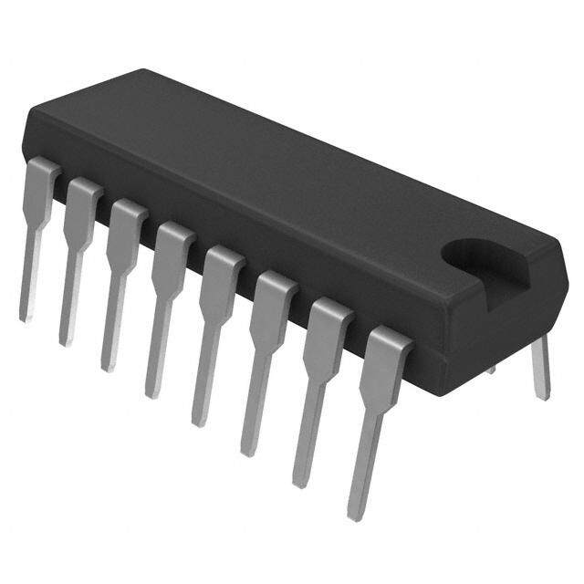
ICGOO在线商城 > 集成电路(IC) > 数据采集 - 数模转换器 > AD7533JN
- 型号: AD7533JN
- 制造商: Analog
- 库位|库存: xxxx|xxxx
- 要求:
| 数量阶梯 | 香港交货 | 国内含税 |
| +xxxx | $xxxx | ¥xxxx |
查看当月历史价格
查看今年历史价格
AD7533JN产品简介:
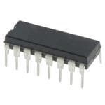
ICGOO电子元器件商城为您提供AD7533JN由Analog设计生产,在icgoo商城现货销售,并且可以通过原厂、代理商等渠道进行代购。 AD7533JN价格参考。AnalogAD7533JN封装/规格:数据采集 - 数模转换器, 10 位 数模转换器 1 16-PDIP。您可以下载AD7533JN参考资料、Datasheet数据手册功能说明书,资料中有AD7533JN 详细功能的应用电路图电压和使用方法及教程。
| 参数 | 数值 |
| 产品目录 | 集成电路 (IC)半导体 |
| 描述 | IC DAC 10BIT MULTIPLYING 16-DIP数模转换器- DAC IC Low Cost 10-Bit Multiplying |
| 产品分类 | |
| 品牌 | Analog Devices |
| 产品手册 | |
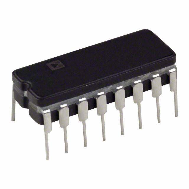
| 产品图片 |
|
| rohs | 否不符合限制有害物质指令(RoHS)规范要求 |
| 产品系列 | 数据转换器IC,数模转换器- DAC,Analog Devices AD7533JN- |
| 数据手册 | |
| 产品型号 | AD7533JN |
| 产品培训模块 | http://www.digikey.cn/PTM/IndividualPTM.page?site=cn&lang=zhs&ptm=19145http://www.digikey.cn/PTM/IndividualPTM.page?site=cn&lang=zhs&ptm=18614http://www.digikey.cn/PTM/IndividualPTM.page?site=cn&lang=zhs&ptm=26125http://www.digikey.cn/PTM/IndividualPTM.page?site=cn&lang=zhs&ptm=26140http://www.digikey.cn/PTM/IndividualPTM.page?site=cn&lang=zhs&ptm=26150http://www.digikey.cn/PTM/IndividualPTM.page?site=cn&lang=zhs&ptm=26147 |
| 产品种类 | 数模转换器- DAC |
| 位数 | 10 |
| 供应商器件封装 | 16-PDIP |
| 分辨率 | 10 bit |
| 包装 | 管件 |
| 商标 | Analog Devices |
| 安装类型 | 通孔 |
| 安装风格 | Through Hole |
| 封装 | Tube |
| 封装/外壳 | 16-DIP(0.300",7.62mm) |
| 封装/箱体 | PDIP-16 |
| 工作温度 | -40°C ~ 85°C |
| 工厂包装数量 | 25 |
| 建立时间 | 600ns |
| 接口类型 | Parallel |
| 数据接口 | 并联 |
| 最大功率耗散 | 30 mW |
| 最大工作温度 | + 125 C |
| 最小工作温度 | - 55 C |
| 标准包装 | 25 |
| 电压参考 | External |
| 电压源 | 单电源 |
| 电源电压-最大 | 16.5 V |
| 电源电压-最小 | 5 V |
| 积分非线性 | +/- 0.2 % FSR |
| 稳定时间 | 600 ns |
| 系列 | AD7533 |
| 结构 | Segment |
| 转换器数 | 1 |
| 转换器数量 | 1 |
| 输出数和类型 | 2 电流,单极2 电流,双极 |
| 输出类型 | Current |
| 采样比 | 1.7 MSPs |
| 采样率(每秒) | 1.7M |





- 商务部:美国ITC正式对集成电路等产品启动337调查
- 曝三星4nm工艺存在良率问题 高通将骁龙8 Gen1或转产台积电
- 太阳诱电将投资9.5亿元在常州建新厂生产MLCC 预计2023年完工
- 英特尔发布欧洲新工厂建设计划 深化IDM 2.0 战略
- 台积电先进制程称霸业界 有大客户加持明年业绩稳了
- 达到5530亿美元!SIA预计今年全球半导体销售额将创下新高
- 英特尔拟将自动驾驶子公司Mobileye上市 估值或超500亿美元
- 三星加码芯片和SET,合并消费电子和移动部门,撤换高东真等 CEO
- 三星电子宣布重大人事变动 还合并消费电子和移动部门
- 海关总署:前11个月进口集成电路产品价值2.52万亿元 增长14.8%



PDF Datasheet 数据手册内容提取
CMOS Low Cost, 10-Bit Multiplying DAC AD7533 FEATURES GENERAL DESCRIPTION Low cost 10-bit DAC The AD7533 is a low cost, 10-bit, 4-quadrant multiplying DAC Low cost AD7520 replacement manufactured using an advanced thin-film-on-monolithic- Linearity: ½ LSB, 1 LSB, or 2 LSB CMOS wafer fabrication process. Low power dissipation Pin and function equivalent to the AD7520 industry standard, Full 4-quadrant multiplying DAC the AD7533 is recommended as a lower cost alternative for old CMOS/TTL direct interface AD7520 sockets or new 10-bit DAC designs. Latch free (protection Schottky not required) AD7533 application flexibility is demonstrated by its ability to Endpoint linearity interface to TTL or CMOS, operate on 5 V to 15 V power, and provide proper binary scaling for reference inputs of either APPLICATIONS positive or negative polarity. Digitally controlled attenuators Programmable gain amplifiers Function generation Linear automatic gain controls FUNCTIONAL BLOCK DIAGRAM 10kΩ 10kΩ 10kΩ VREF 20kΩ 20kΩ 20kΩ 20kΩ 20kΩ S1 S2 S3 SN IOUT2 IOUT1 10kΩ RFB BIT 1 (MSBD)IGITAL INBPIUTT 2S (DTL/TTL/CMBOIST 3COMPATIBLBEIT) 10 (LSB) 01134-001 Figure 1. Rev. C Information furnished by Analog Devices is believed to be accurate and reliable. However, no responsibility is assumed by Analog Devices for its use, nor for any infringements of patents or other One Technology Way, P.O. Box 9106, Norwood, MA 02062-9106, U.S.A. rights of third parties that may result from its use. Specifications subject to change without notice. No license is granted by implication or otherwise under any patent or patent rights of Analog Devices. Tel: 781.329.4700 www.analog.com Trademarks and registered trademarks are the property of their respective owners. Fax: 781.461.3113 ©2007 Analog Devices, Inc. All rights reserved.
AD7533 TABLE OF CONTENTS Features..............................................................................................1 Circuit Description............................................................................7 Applications.......................................................................................1 General Circuit Information........................................................7 General Description.........................................................................1 Equivalent Circuit Analysis.........................................................7 Functional Block Diagram..............................................................1 Operation............................................................................................8 Revision History...............................................................................2 Unipolar Binary Code..................................................................8 Specifications.....................................................................................3 Bipolar (Offset Binary) Code.......................................................8 Absolute Maximum Ratings............................................................4 Applications........................................................................................9 ESD Caution..................................................................................4 Outline Dimensions.......................................................................10 Terminology......................................................................................5 Ordering Guide..........................................................................12 Pin Configurations and Function Descriptions...........................6 REVISION HISTORY 3/07—Rev. B to Rev. C 3/04—Rev. 0 to Rev. A Changes to Table 1............................................................................3 Changes to Specifications.................................................................2 Changes to Table 2............................................................................4 Changes to Absolute Maximum Ratings........................................3 Changes to Figure 13, Figure 14, and Figure 17...........................9 Changes to Ordering Guide.............................................................3 Updated Outline Dimensions.......................................................10 Updated Outline Dimensions..........................................................7 Changes to Ordering Guide..........................................................12 1/06—Rev. A to Rev. B Updated Format..................................................................Universal Changes to Absolute Maximum Ratings.......................................4 Added Pin Configurations and Function Descriptions Section................................................6 Updated Outline Dimensions.......................................................10 Changes to Ordering Guide..........................................................12 Rev. C | Page 2 of 12
AD7533 SPECIFICATIONS V = 15 V, V 1 = V 2 = 0 V, V = 10 V, unless otherwise noted. DD OUT OUT REF Table 1. Parameter T = 25°C T = Operating Range Test Conditions A A STATIC ACCURACY Resolution 10 Bits 10 Bits Relative Accuracy1 AD7533JN, AD7533AQ, ±0.2% FSR maximum ±0.2% FSR maximum AD7533SQ, AD7533JP AD7533KN, AD7533BQ, ±0.1% FSR maximum ±0.1% FSR maximum AD7533KP, AD7533TE AD7533LN, AD7533CQ, AD7533UQ ±0.05% FSR maximum ±0.05% FSR maximum DNL ±1 LSB maximum ±1 LSB maximum Gain Error2, 3 ±1% FS maximum ±1% FS maximum Digital input = V INH Supply Rejection4 ∆Gain/∆V 0.001%/% maximum 0.001%/% maximum Digital inputs = V , V = 14 V to 17 V DD INH DD Output Leakage Current I 1 ±5 nA maximum ±200 nA maximum Digital inputs = V , V = ±10 V OUT INL REF I 2 ±5 nA maximum ±200 nA maximum Digital inputs = V , V = ±10 V OUT INH REF DYNAMIC ACCURACY Output Current Settling Time 600 ns maximum4 800 ns5 To 0.05% FSR; R = 100 Ω, digital LOAD inputs = V to V or V to V INH INL INL INH Feedthrough Error ±0.05% FSR maximum5 ±0.1% FSR maximum5 Digital inputs = V , V = ±10 V, INL REF 100 kHz sine wave Propagation Delay 100 ns typical 100 ns typical Glitch Impulse 100 nV-s typical 100 nV-s typical REFERENCE INPUT Input Resistance (VREF) 5 kΩ min, 20 kΩ maximum 5 kΩ min, 20 kΩ maximum6 11 kΩ nominal ANALOG OUTPUTS Output Capacitance C 50 pF maximum5 100 pF maximum5 Digital inputs = V IOUT1 INH C 20 pF maximum5 35 pF maximum5 IOUT2 C 30 pF maximum5 35 pF maximum5 IOUT1 C 50 pF maximum5 100 pF maximum5 Digital inputs = V IOUT2 INL DIGITAL INPUTS Input High Voltage (V ) 2.4 V minimum 2.4 V minimum INH Input Low Voltage (V ) 0.8 V maximum 0.8 V maximum INL Input Leakage Current (I ) ±1 μA maximum ±1 μA maximum V = 0 V and V IN IN DD Input Capacitance (C ) 8 pF maximum5 8 pF maximum5 IN POWER REQUIREMENTS V 15 V ± 10% 15 V ± 10% Rated accuracy DD V Ranges5 5 V to 16 V 5 V to 16 V Functionality with degraded performance DD I 2 mA maximum 2 mA maximum Digital inputs = V or V D DD INL INH 25 μA maximum 50 μA maximum Digital inputs over V IN 1 FSR = full-scale range. 2 Full scale (FS) = VREF. 3 Maximum gain change from TA = 25°C to TMIN or TMAX is ±0.1% FSR. 4 AC parameter, sample tested to ensure specification compliance. 5 Guaranteed, not tested. 6 Absolute temperature coefficient is approximately −300 ppm/°C. Rev. C | Page 3 of 12
AD7533 ABSOLUTE MAXIMUM RATINGS T = 25 °C unless otherwise noted. A Stresses above those listed under Absolute Maximum Ratings Table 2. may cause permanent damage to the device. This is a stress Parameter Rating rating only; functional operation of the device at these or any V to GND −0.3 V, +17 V DD other conditions above those indicated in the operational R to GND ±25 V FB section of this specification is not implied. Exposure to absolute V to GND ±25 V REF maximum rating conditions for extended periods may affect Digital Input Voltage Range −0.3 V to V + 0.3 V DD device reliability. I 1, I 2 to GND −0.3 V to V OUT OUT DD Power Dissipation (Any Package) To 75°C 450 mW ESD CAUTION Derates above 75°C by 6 mW/°C Operating Temperature Range Plastic (JN, JP, KN, KP, LN Versions) −40°C to +85°C Hermetic (AQ, BQ, CQ Versions) −40°C to +85°C Hermetic (SQ, TE, UQ Versions) −55°C to +125°C Storage Temperature Range −65°C to +150°C Lead Temperature (Soldering, 10 sec) 300°C Rev. C | Page 4 of 12
AD7533 TERMINOLOGY Relative Accuracy Gain Error Relative accuracy or endpoint nonlinearity is a measure of the Gain error is a measure of the output error between an ideal maximum deviation from a straight line passing through the DAC and the actual device output. It is measured with all 1s in endpoints of the DAC transfer function. It is measured after the DAC after offset error is adjusted out and is expressed in LSBs. adjusting for ideal zero and full scale and is expressed in % of Gain error is adjustable to zero with an external potentiometer. full-scale range or (sub) multiples of 1 LSB. Feedthrough Error Resolution Error caused by capacitive coupling from V to output with all REF Value of the LSB. For example, a unipolar converter with n bits switches off. has a resolution of (2–n) (V ). A bipolar converter of n bits has REF Output Capacitance a resolution of [2–(n–1)] (V ). Resolution in no way implies REF Capacity from I 1 and I 2 terminals to ground. OUT OUT linearity. Output Leakage Current Settling Time Current that appears on I 1 terminal with all digital inputs OUT Time required for the output function of the DAC to settle to low or on I 2 terminal when all inputs are high. OUT within ½ LSB for a given digital input stimulus, that is, 0 to full scale. Rev. C | Page 5 of 12
AD7533 PIN CONFIGURATIONS AND FUNCTION DESCRIPTIONS IIOOUUTT12 12 1165 RVRFBEF I23OUTI12OUTNC1 2RFB0 1VREF9 GND 3 AD7533 14 VDD BIT 1 (MSB) 4 TOP VIEW 13 BIT 10 (LSB) GND4 18VDD BIT 2 5 (Not to Scale) 12 BIT 9 BIT 1 (MSB)5 AD7533 17BIT 10 (LSB) BIT 3 6 11 BIT 8 NC6 16NC TOP VIEW BBIITT 45 78 190 BBIITT 76 01134-002 BBIITT 2378 (Not to Scale) 1154BBIITT 98 Figure 2. 16-Lead PDIP Pin Configuration NC = NO CONNECT BIT 49 1BIT 50 1NC1 1BIT 62 1BIT 73 01134-005 IOUT1 1 16 RFB Figure 5. 20-Terminal LCC Pin Configuration IOUT2 2 15 VREF GND 3 AD7533 14 VDD BIT 1 (MBISTB 2) 45 (NToOt Pto V SIEcWale) 1132 BBIITT 190 (LSB) I2OUT 1IOUT NC RFB VREF BIT 3 6 11 BIT 8 3 2 1 20 19 BBIITT 45 78 190 BBIITT 76 01134-003 BIT 1 (MGSNBD) 45 PININD E1NTFIER 1187 BVDITD 10 (LSB) AD7533 NC 6 16 NC Figure 3. 16-Lead SOIC Pin Configuration TOP VIEW BIT 2 7 (Not to scale) 15 BIT 9 BIT 3 8 14 BIT 8 IOUT1 1 16 RFB 9 10 11 12 13 BIT 1 (IMOGSUNTBD2) 234 ATODP7 V5IE3W3 111543 VVBRDITED F10 (LSB) NBIT 4C =BIT 5 NO NCCONBIT 6NEBIT 7CT 01134-006 BIT 2 5 (Not to Scale) 12 BIT 9 Figure 6. 20-Lead PLCC Pin Configuration BIT 3 6 11 BIT 8 BBIITT 45 78 190 BBIITT 76 01134-004 Figure 4. 16-Lead CERDIP Pin Configuration Table 3. Pin Function Descriptions Pin Number 16-Lead PDIP, SOIC, CERDIP 20-Lead LCC, PLCC Mnemonic Description 1 2 I 1 DAC Current Output. OUT 2 3 I 2 DAC Analog Ground. This pin should normally be tied to the OUT analog ground of the system. 3 4 GND Ground. 4 to 13 5, 7 to 10, 12 to 15, 17 BIT 1 to BIT 10 MSB to LSB. 14 18 V Positive Power Supply Input. These parts can be operated from DD a supply of 5 V to 16 V. 15 19 V DAC Reference Voltage Input Terminal. REF 16 20 R DAC Feedback Resistor Pin. Establish voltage output for the DAC FB by connecting R to external amplifier output. FB NA 1, 6, 11, 16 NC No Connect. Rev. C | Page 6 of 12
AD7533 CIRCUIT DESCRIPTION V+ GENERAL CIRCUIT INFORMATION 1 3 TO LADDER The AD7533 is a 10-bit multiplying DAC that consists of a 4 6 highly stable thin-film R-2R ladder and ten CMOS current DTL/TTL/ 250Ω CMOS switches on a monolithic chip. Most applications require the INPUT 8 9 addition of only an output operational amplifier and a voltage 2 5 7 oTrh ceu srimrenplti frieefder Den/cAe .c ircuit is shown in Figure 7. An inverted IOUT2 IOUT1 01134-007 Figure 8. CMOS Switch R- 2R ladder structure is used, that is, the binarily weighted currents are switched between the I 1 and I 2 bus lines, EQUIVALENT CIRCUIT ANALYSIS OUT OUT thus maintaining a constant current in each ladder leg The equivalent circuits for all digital inputs high and digital independent of the switch state. inputs low are shown in Figure 9 and Figure 10. In Figure 9 with 10kΩ 10kΩ 10kΩ all digital inputs low, the reference current is switched to I 2. VREF OUT The current source I is composed of surface and junction 20kΩ 20kΩ 20kΩ 20kΩ 20kΩ LEAKAGE leakages to the substrate, while the I/1024 current source represents S1 S2 S3 SN a constant 1-bit current drain through the termination resistor IOUT2 on the R-2R ladder. The on capacitance of the output N channel switch is 100 pF, as shown on the I 2 terminal. The off switch IOUT1 OUT 10kΩ RFB capacitance is 35 pF, as shown on the IOUT1 terminal. Analysis of the circuit for all digital inputs high, as shown in Figure 10, is BIT 1 (MSBD)IGITAL INBPIUTT 2S (DTL/TTL/CMBOIST 3COMPATIBLBEIT) 10 (LSB) 01134-001 sTiemrmilainr atol IFOiUgTu1r. eT 9h;e hroefwoerev,e trh, tehree iosn t hswe 1it0c0h epsF a raet tnhoawt toenrm inal. Figure 7. Functional Diagram One of the CMOS current switches is shown in Figure 8. The RFB geometries of Device 1, Device 2, and Device 3 are optimized to R make the digital control inputs DTL/TTL/CMOS compatible IOUT1 over the full military temperature range. The input stage drives R 10kΩ ILEAKAGE 35pF two inverters (Device 4, Device 5, Device 6, and Device 7), IREF which in turn drive the two output N channels. The on VREF IOUT2 R rdersoipst aancrcoesss o efa tchhe sswwiittcchh eiss tahree sbainmaer.i lFyo sre eaxleadm spol et,h Sawt tihtceh v 1o litna ge I/1024 ILEAKAGE 100pF 01134-008 Figure 8 is designed for an on resistance of 20 Ω, Switch 2 for Figure 9. Equivalent Circuit—All Digital Inputs Low 40 Ω, and so on. For a 10 V reference input, the current through Switch 1 is 0.5 mA, the current through Switch 2 is 0.25 mA, RFB and so on, thus maintaining a constant 10 mV drop across each IREF R 10kΩ R switch. It is essential that each switch voltage drop be equal if VREF IOUT1 the binarily weighted current division property of the ladder is R I/1024 ILEAKAGE 100pF to be maintained. IOUT2 ILEAKAGE 35pF 01134-009 Figure 10. Equivalent Circuit—All Digital Inputs High Rev. C | Page 7 of 12
AD7533 OPERATION UNIPOLAR BINARY CODE BIPOLAR (OFFSET BINARY) CODE Table 4. Unipolar Binary Operation Table 5. Unipolar Binary Operation (2-Quadrant Multiplication) (4-Quadrant Multiplication) Digital Input Analog Output Digital Input Analog Output MSB LSB (VOUT as shown in Figure 11) MSB LSB (VOUT as shown in Figure 12) 1 1 1 1 1 1 1 1 1 1 ⎛1023⎞ 1 1 1 1 1 1 1 1 1 1 ⎛511⎞ −V ⎜ ⎟ +V ⎜ ⎟ REF ⎝1024⎠ REF ⎝512⎠ 1 0 0 0 0 0 0 0 0 1 ⎛ 513 ⎞ 1 0 0 0 0 0 0 0 0 1 ⎛ 1 ⎞ −V ⎜ ⎟ +V ⎜ ⎟ REF ⎝1024⎠ REF ⎝512⎠ 1 0 0 0 0 0 0 0 0 0 ⎛ 512 ⎞ ⎛V ⎞ 1 0 0 0 0 0 0 0 0 0 0 −V ⎜ ⎟=⎜ REF⎟ REF ⎝1024⎠ ⎝ 2 ⎠ 0 1 1 1 1 1 1 1 1 1 ⎛ 1 ⎞ −V ⎜ ⎟ 0 1 1 1 1 1 1 1 1 1 ⎛ 511 ⎞ REF ⎝512⎠ −VREF ⎜⎝1024⎟⎠ 0 0 0 0 0 0 0 0 0 1 ⎛511⎞ −V ⎜ ⎟ 0 0 0 0 0 0 0 0 0 1 ⎛ 1 ⎞ REF ⎝512⎠ −VREF ⎜⎝1024⎟⎠ 0 0 0 0 0 0 0 0 0 0 ⎛512⎞ −V ⎜ ⎟ 0 0 0 0 0 0 0 0 0 0 ⎛ 0 ⎞ REF ⎝512⎠ −VREF ⎜⎝1024⎟⎠=0 Nominal LSB magnitude for the circuit of Figure 12 is given by Nominal LSB magnitude for the circuit of Figure 11 is given by ⎛ 1 ⎞ LSB=V ⎜ ⎟ ⎛ 1 ⎞ REF⎝512⎠ LSB=V ⎜ ⎟ REF ⎝1024⎠ BIPOLAR ANALOG INPUT BIPOLAR ±10V VDD ANALOG INPUT ±10V VDD R1 R4 MSB14kRΩ1 15 VREF 14 16RFBIOU3T3R102Ω C1 BDIPIIGONILPTAUARTL MLSSBB11k43Ω15AVDRE7F53134 16 12 II3OO3RUU02TTΩ12 C1 A1 120R0k3kΩΩ 20ARk25Ω VOUT UNDIPIIGONILPTAUARTL LSB 13 AD7533 12 IOUT2 VOUT GN3D 5Rk6Ω 3 NOTES GND 123...WRCR311H , APERHNN4AD ,U S ARSENI2 NDC UG ORS MH5E IDPSGE EOHNL NSSELAPCYETT IEEIOFDD NG AF A(OM5IpNRPF LAM ITDFAOIJTE U1CRS5HSpTI.FNM)GE M NAATNY ID SB TRER ERAQECUQKIRUINEIRGDE..D 01134-011 NOTES Figure 12. Bipolar Operation (4-Quadrant Multiplication) 12..WCR11H PAEHNNAD US RSE2I N CUGOS MHEIDPGE OHN NSSLPAYET EIIOFD NG A A(M5IpNPF LA ITDFOIJE U1RS5.pTFM)E MNATY I SB RE ERQEUQIRUEIRDE.D 01134-010 Figure 11. Unipolar Binary Operation (2-Quadrant Multiplication) Rev. C | Page 8 of 12
AD7533 APPLICATIONS BIPOLAR ANALOG INPUT ±10V VDD 15 VREF 14 RFB 10kΩ 10kΩ MSB 16 4 IOUT1 1/2AD7512DIJN 1 MBIATGSNITUDE LSB 13 AD7533 2 IOUT2 OP97 5kΩ OP97 VOUT DIGITAL INPUT SIGN BIT 3 GND 01134-012 Figure 13. 10-Bit and Sign Multiplying DAC CALIBRATE 4.7kΩ 10V 1kΩ SQUARE +15V 6.8V OP97 WAVE VDD NC (2) 110%kΩ 110%kΩ VREF Ct 15 14 MSB 16 DIGITAL 4 IOUT1 FREQUENCY 1 CONWTORRODL LSB 13 AD7533 2 IOUT2 OP97 TWRAIAVNEGULAR 3 1 f = N ( ) GND R0 t< = N 1≤08 k(R1Ω t C21t0) 01134-013 Figure 14. Programmable Function Generator +15V TEST INPUT VIN VREF +15V (0TO –VREF) RFB 16 14 IOUT2 2 AD7533 4 MSB DIBNIIGTP UI1TTAL DIGITAL MSB 4 15 14 16 1 IOUT1 ACOD7M9P0ARATOR IOUT1 1 3 15 13 LSB “BDIT” 10 (TEST ILNIPMUITT) LSB 13 AD7533 2 IOUT2 FTAESILT/PASS GND VREVFOUT 0Vw Oh<DU eDTr=e=≤:B11–I200TV1D22 I134N+BI2T2 2 +…BI2T1 010 01134-014 Figure 17. DigGitN3aDlly Programmable Limit Detector 01134-016 Figure 15. Divider (Digitally Controlled Gain) VREF . +15V R1 VOUT 15 14 RFB BIT 1 MSB 4 16 IOUT1 R2 DIGITAL 1 INPUT AD7533 BIT“ D10” LSB 13 2 IOUT2 –VREFD 3 VOUT= VREF= R 1 R + 2 R 2 – R1R +1D R2 GND where: BIT 1 BIT 2 BIT 10 D= + +… 02 <1 D≤ 1120022234 210 01134-015 Figure 16. Modified Scale Factor and Offset Rev. C | Page 9 of 12
AD7533 OUTLINE DIMENSIONS 0.800 (20.32) 0.790 (20.07) 0.780 (19.81) 16 9 0.280 (7.11) 0.250 (6.35) 1 8 0.240 (6.10) 0.325 (8.26) 0.310 (7.87) 0.100 (2.54) 0.300 (7.62) BSC 0.060 (1.52) 0.195 (4.95) 0.210 (5.33) MAX 0.130 (3.30) MAX 0.115 (2.92) 0.015 0.150 (3.81) (0.38) 0.015 (0.38) 0.130 (3.30) MIN GAUGE 0.115 (2.92) SEATING PLANE 0.014 (0.36) PLANE 0.010 (0.25) 0.022 (0.56) 0.008 (0.20) 0.005 (0.13) 0.430 (10.92) 0.018 (0.46) MIN MAX 0.014 (0.36) 0.070 (1.78) 0.060 (1.52) 0.045 (1.14) COMPLIANTTO JEDEC STANDARDS MS-001-AB CONTROLLING DIMENSIONSARE IN INCHES; MILLIMETER DIMENSIONS (RCINOEFRPEANRREEREN NLCTEEHA EODSNSEL MSY)AAAYNR BDEE AR CROOEU NNNFODIGETUDAR-POEPFDRFOA INSPC RWHIAH ETOEQL UFEIO VORAR LU EHSNAETL ISFN FLDOEEARSDIGSN.. 073106-B Figure 18. 16-Lead Plastic Dual In-Line Package [PDIP] (N-16) Dimensions shown in inches and (millimeters) 10.50 (0.4134) 10.10 (0.3976) 16 9 7.60 (0.2992) 7.40 (0.2913) 1 10.65 (0.4193) 8 10.00 (0.3937) 1.27 (0.0500) 0.75 (0.0295) BSC 2.65 (0.1043) 0.25 (0.0098) 45° 0.30 (0.0118) 2.35 (0.0925) 8° 0.10 (0.0039) 0° COPLANARITY 0.10 0.51 (0.0201) SPLEAATNIENG 0.33 (0.0130) 1.27 (0.0500) 0.31 (0.0122) 0.20 (0.0079) 0.40 (0.0157) COMPLIANTTO JEDEC STANDARDS MS-013-AA C(RINOEFNPEATRRREOENNLCLTEIHN EOGSN EDLSIYM)AEANNRDSEI AORRNOESU NANORDEET DAIN-PO MPFRIFLO LMPIIMRLELIATIMTEEER TFSEO; RIRN ECUQHSU EDI VIINMA LEDENENSSTIIOGSN NFS.OR 112906-B Figure 19. 16-Lead Standard Small Outline Package [SOIC_W] Wide Body (RW-16) Dimensions shown in millimeters and (inches) Rev. C | Page 10 of 12
AD7533 0.005 (0.13) MIN 0.098 (2.49) MAX 16 9 0.310 (7.87) 0.220 (5.59) 1 8 PIN 1 0.100 (2.54) BSC 0.320 (8.13) 0.290 (7.37) 0.840 (21.34) MAX 0.060 (1.52) 0.200 (5.08) 0.015 (0.38) MAX 0.150 0.200 (5.08) (3.81) 0.125 (3.18) MIN SEATING 0.015 (0.38) 0.023 (0.58) 0.070 (1.78) PLANE 15° 0.008 (0.20) 0.014 (0.36) 0.030 (0.76) 0° CONTROLLING DIMENSIONS ARE IN INCHES; MILLIMETER DIMENSIONS (IN PARENTHESES) ARE ROUNDED-OFF INCH EQUIVALENTS FOR REFERENCE ONLY AND ARE NOT APPROPRIATE FOR USE IN DESIGN. Figure 20. 16-Lead Ceramic Dual In-Line Package [CERDIP] (Q-16) Dimensions shown in inches and (millimeters) 0.200 (5.08) 0.075 (1.91) REF 0.100 (2.54) REF 0.100 (2.54) REF 0.064 (1.63) 0.095 (2.41) 0.015 (0.38) 0.075 (1.90) MIN 19 3 18 20 4 0.028 (0.71) 0.358 (9.09) 0.358 1 0.342 (8.69) (9.09) 0.011 (0.28) BOTTOM 0.022 (0.56) SQ MSAQX 0.007 R(0 T.1Y8P) VIEW 0.050 (1.27) 0.075 (1.91) 14 8 BSC REF 13 9 45° TYP 0.088 (2.24) 0.055 (1.40) 0.150 (3.81) 0.054 (1.37) 0.045 (1.14) BSC C(RINOEFNPETARRREOENNLCLTEIHN EOGSN EDLSIYM)AEANNRDSEI AORRNOESU NANORDEET DAIN-PO IPFNRFCO HINPECRSHI;A METEQIL UFLIOIVMRAE LUTEESNRET DISNI M FDOEERNSSIGIONN.S 022106-A Figure 21. 20-Terminal Ceramic Leadless Chip Carrier [LCC] (E-20-1) Dimensions shown in inches and (millimeters) 0.180 (4.57) 0.048 (1.22 ) 0.165 (4.19) 0.042 (1.07) 0.056 (1.42) 0.042 (1.07) 0M.I2N0 (0.51) 0.020R (0.50) 3 19 0.021 (0.53) 00..004482 ((11..2027)) 4 IDEPNITNI F1IER 18 (01..02570) 0.013 (0.33)0.330 (8.38) BOTTOM TOP VIEW BSC 0.032 (0.81)0.290 (7.37) VIEW (PINS DOWN) 0.026 (0.66) (PINS UP) 8 14 9 13 0.020 0.045 (1.14) (0.R51) 00..335560 ((98..0849))SQ 0.025 (0.64) R 0.120 (3.04) 0.395 (10.03)SQ 0.090 (2.29) 0.385 (9.78) COMPLIANT TO JEDEC STANDARDS MO-047-AA CONTROLLING DIMENSIONS ARE IN INCHES; MILLIMETER DIMENSIONS (IN PARENTHESES) ARE ROUNDED-OFF INCH EQUIVALENTS FOR REFERENCE ONLY AND ARE NOT APPROPRIATE FOR USE IN DESIGN. Figure 22. 20-Lead Plastic Leaded Chip Carrier [PLCC] (P-20) Dimensions shown in inches and (millimeters) Rev. C | Page 11 of 12
AD7533 ORDERING GUIDE Nonlinearity Model Temperature Range Package Description Package Option (% FSR max) AD7533ACHIPS DIE AD7533JN −40°C to +85°C 16-Lead Plastic Dual In-Line Package [PDIP] N-16 ±0.2 AD7533JNZ1 −40°C to +85°C 16-Lead Plastic Dual In-Line Package [PDIP] N-16 ±0.2 AD7533KN −40°C to +85°C 16-Lead Plastic Dual In-Line Package [PDIP] N-16 ±0.1 AD7533KNZ1 −40°C to +85°C 16-Lead Plastic Dual In-Line Package [PDIP] N-16 ±0.1 AD7533LN −40°C to +85°C 16-Lead Plastic Dual In-Line Package [PDIP] N-16 ±0.05 AD7533LNZ1 −40°C to +85°C 16-Lead Plastic Dual In-Line Package [PDIP] N-16 ±0.05 AD7533JP −40°C to +85°C 20-Lead Plastic Leaded Chip Carrier [PLCC] P-20 ±0.2 AD7533JP-REEL −40°C to +85°C 20-Lead Plastic Leaded Chip Carrier [PLCC] P-20 ±0.2 AD7533JPZ1 −40°C to +85°C 20-Lead Plastic Leaded Chip Carrier [PLCC] P-20 ±0.2 AD7533JPZ-REEL1 −40°C to +85°C 20-Lead Plastic Leaded Chip Carrier [PLCC] P-20 ±0.2 AD7533KP −40°C to +85°C 20-Lead Plastic Leaded Chip Carrier [PLCC] P-20 ±0.1 AD7533KP-REEL −40°C to +85°C 20-Lead Plastic Leaded Chip Carrier [PLCC] P-20 ±0.1 AD7533KPZ1 −40°C to +85°C 20-Lead Plastic Leaded Chip Carrier [PLCC] P-20 ±0.1 AD7533KPZ-REEL1 −40°C to +85°C 20-Lead Plastic Leaded Chip Carrier [PLCC] P-20 ±0.1 AD7533KR −40°C to +85°C 16-Lead Standard Small Outline Package [SOIC_W] RW-16 ±0.1 AD7533KR-REEL −40°C to +85°C 16-Lead Standard Small Outline Package [SOIC_W] RW-16 ±0.1 AD7533KRZ1 −40°C to +85°C 16-Lead Standard Small Outline Package [SOIC_W] RW-16 ±0.1 AD7533KRZ-REEL1 −40°C to +85°C 16-Lead Standard Small Outline Package [SOIC_W] RW-16 ±0.1 AD7533AQ −40°C to +85°C 16-Lead Ceramic Dual In-Line Package [CERDIP] Q-16 ±0.2 AD7533BQ −40°C to +85°C 16-Lead Ceramic Dual In-Line Package [CERDIP] Q-16 ±0.1 AD7533CQ −40°C to +85°C 16-Lead Ceramic Dual In-Line Package [CERDIP] Q-16 ±0.05 AD7533SQ −55°C to +125°C 16-Lead Ceramic Dual In-Line Package [CERDIP] Q-16 ±0.2 AD7533UQ −55°C to +125°C 16-Lead Ceramic Dual In-Line Package [CERDIP] Q-16 ±0.05 AD7533UQ/883B −55°C to +125°C 16-Lead Ceramic Dual In-Line Package [CERDIP] Q-16 ±0.05 AD7533TE/883B −55°C to +125°C 20-Terminal Ceramic Leadless Chip Carrier [LCC] E-20-1 ±0.1 1Z = RoHS compliant part. ©2007 Analog Devices, Inc. All rights reserved. Trademarks and registered trademarks are the property of their respective owners. C01134-0-3/07(C) T TTT Rev. C | Page 12 of 12
Mouser Electronics Authorized Distributor Click to View Pricing, Inventory, Delivery & Lifecycle Information: A nalog Devices Inc.: AD7533JN AD7533KN AD7533TE/883B AD7533KR AD7533JP AD7533LN
 Datasheet下载

