ICGOO在线商城 > 集成电路(IC) > 数据采集 - ADCs/DAC - 专用型 > AD7147ACPZ-1500RL7

 Datasheet下载
- 型号: AD7147ACPZ-1500RL7
- 制造商: Analog
- 库位|库存: xxxx|xxxx
- 要求:
| 数量阶梯 | 香港交货 | 国内含税 |
| +xxxx | $xxxx | ¥xxxx |
查看当月历史价格
查看今年历史价格
AD7147ACPZ-1500RL7产品简介:
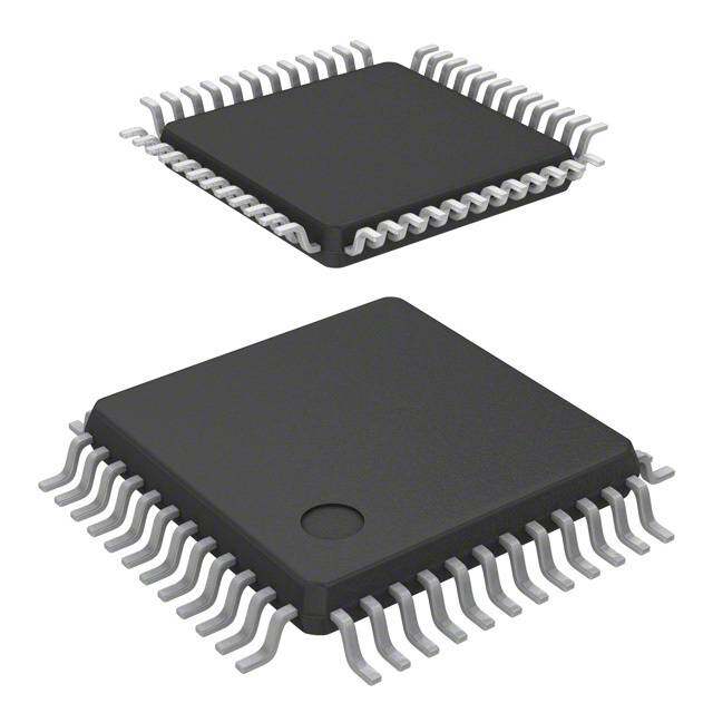
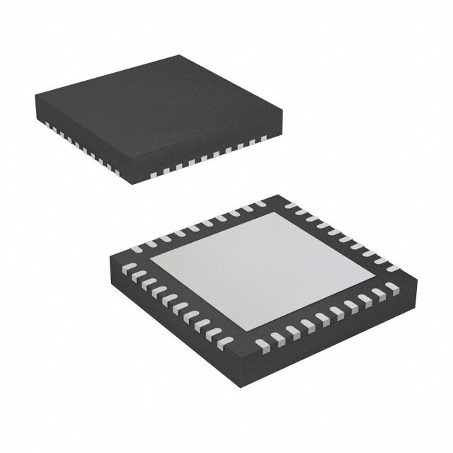
ICGOO电子元器件商城为您提供AD7147ACPZ-1500RL7由Analog设计生产,在icgoo商城现货销售,并且可以通过原厂、代理商等渠道进行代购。 AD7147ACPZ-1500RL7价格参考。AnalogAD7147ACPZ-1500RL7封装/规格:数据采集 - ADCs/DAC - 专用型, Capacitance-to-Digital Converter 16 bit 250k I²C, Serial 24-LFCSP-WQ (4x4)。您可以下载AD7147ACPZ-1500RL7参考资料、Datasheet数据手册功能说明书,资料中有AD7147ACPZ-1500RL7 详细功能的应用电路图电压和使用方法及教程。
| 参数 | 数值 |
| 产品目录 | 集成电路 (IC)半导体 |
| 描述 | IC CAP-TO-DGTL CONV PROG 24LFCSP触摸屏转换器和控制器 Prog Cntlr for SGL Electrde CAP Sensors |
| 产品分类 | |
| 品牌 | Analog Devices Inc |
| 产品手册 | |
| 产品图片 |
|
| rohs | 符合RoHS无铅 / 符合限制有害物质指令(RoHS)规范要求 |
| 产品系列 | 数据转换器IC,触摸屏转换器和控制器,Analog Devices AD7147ACPZ-1500RL7CapTouch™ |
| 数据手册 | |
| 产品型号 | AD7147ACPZ-1500RL7 |
| PCN其它 | |
| 产品目录页面 | |
| 产品种类 | 触摸屏转换器和控制器 |
| 供应商器件封装 | 24-LFCSP-VQ(4x4) |
| 其它名称 | AD7147ACPZ-1500RL7TR |
| 分辨率 | 16 bit |
| 分辨率(位) | 16 b |
| 包装 | 带卷 (TR) |
| 商标 | Analog Devices |
| 安装类型 | 表面贴装 |
| 安装风格 | SMD/SMT |
| 封装 | Reel |
| 封装/外壳 | 24-VFQFN 裸露焊盘,CSP |
| 封装/箱体 | LFCSP-24 |
| 工作温度 | -40°C ~ 85°C |
| 工厂包装数量 | 500 |
| 数据接口 | I²C, 串行 |
| 最大工作温度 | + 85 C |
| 最小工作温度 | - 40 C |
| 标准包装 | 500 |
| 电压-电源 | 2.6 V ~ 3.6 V |
| 电压源 | 单电源 |
| 类型 | 电容数字转换器 |
| 系列 | AD7147 |
| 输入类型 | Single-Ended |
| 配用 | /product-detail/zh/EVAL-AD7147EBZ/EVAL-AD7147EBZ-ND/1805686/product-detail/zh/EVAL-AD7147-1EBZ/EVAL-AD7147-1EBZ-ND/1805685 |
| 采样率(每秒) | 250k |


- 商务部:美国ITC正式对集成电路等产品启动337调查
- 曝三星4nm工艺存在良率问题 高通将骁龙8 Gen1或转产台积电
- 太阳诱电将投资9.5亿元在常州建新厂生产MLCC 预计2023年完工
- 英特尔发布欧洲新工厂建设计划 深化IDM 2.0 战略
- 台积电先进制程称霸业界 有大客户加持明年业绩稳了
- 达到5530亿美元!SIA预计今年全球半导体销售额将创下新高
- 英特尔拟将自动驾驶子公司Mobileye上市 估值或超500亿美元
- 三星加码芯片和SET,合并消费电子和移动部门,撤换高东真等 CEO
- 三星电子宣布重大人事变动 还合并消费电子和移动部门
- 海关总署:前11个月进口集成电路产品价值2.52万亿元 增长14.8%


PDF Datasheet 数据手册内容提取
CapTouch Programmable Controller for Single-Electrode Capacitance Sensors Data Sheet AD7147 FEATURES FUNCTIONAL BLOCK DIAGRAM Programmable capacitance-to-digital converter (CDC) ACSHIELD VCC GND BIAS 8 11 10 9 Femtofarad resolution 13 capacitance sensor inputs POWER-ON CIN0 19 RESET LOGIC 9 ms update rate, all 13 sensor inputs CIN1 20 No external RC components required CIN2 21 Automatic conversion sequencer EXCITATION SOURCE CIN3 22 On-chip automatic calibration logic Automatic compensation for environmental changes CIN4 23 Automatic adaptive threshold and sensitivity levels CIN5 24 HX AD7147/ CALIBRATION Register map is compatible with the AD7142 CIN6 1 WITCATRI AD7147-1 RAM On-chip RAM to store calibration data CIN7 2 SM SPI-compatible (serial-peripheral-interface-compatible) CIN8 3 16-BIT CALIBRATION Σ-∆ ENGINE serial interface (AD7147) CIN9 4 CDC I2C-compatible serial interface (AD7147-1) CIN10 5 Separate V level for serial interface CIN11 6 CONTROL DRIVE AND DATA Interrupt output and general-purpose input/output (GPIO) CIN12 7 REGISTERS 24-lead, 4 mm × 4 mm LFCSP 2.6 V to 3.3 V supply voltage Low operating current SERIAL INTERFACE INTERRUPT Full power mode: 1 mA VDRIVE 12 AND CONTROL LOGIC ANLDO GGIPCIO 18 GPIO Low power mode: 21.5 μA AQuPaPliLfiIeCdA fTorI OauNtoSm otive applications SSD1D3OA/ASD1D4DI/0SC15LKACD1S6D/1 IN17T 06663-001 Figure 1. Cell phones Personal music and multimedia players Smart handheld devices The AD7147 is designed for single electrode capacitance sensors Television, A/V, and remote controls (grounded sensors). There is an active shield output to Gaming consoles minimize noise pickup in the sensor. Digital still cameras The AD7147 has on-chip calibration logic to compensate for GENERAL DESCRIPTION changes in the ambient environment. The calibration sequence is performed automatically and at continuous intervals as long The AD7147 CapTouch™ controller is designed for use with as the sensors are not touched. This ensures that there are no capacitance sensors implementing functions such as buttons, false or nonregistering touches on the external sensors due to scroll bars, and wheels. The sensors need only one PCB layer, a changing environment. enabling ultrathin applications. The AD7147 has an SPI-compatible serial interface, and the The AD7147 is an integrated CDC with on-chip environmental AD7147-1 has an I2C®-compatible serial interface. Both parts have calibration. The CDC has 13 inputs channeled through a switch an interrupt output, as well as a GPIO. There is a V pin to set matrix to a 16-bit, 250 kHz sigma-delta (∑-Δ) converter. The CDC DRIVE the voltage level for the serial interface independent of V . is capable of sensing changes in the capacitance of the external CC sensors and uses this information to register a sensor activation. The AD7147 is available in a 24-lead, 4 mm × 4 mm LFCSP and By programming the registers, the user has full control over the operates from a 2.6 V to 3.6 V supply. The operating current con- CDC setup. sumption in low power mode is typically 26 μA for 13 sensors. High resolution sensors require minor software to run on the host processor. Rev. E Document Feedback Information furnished by Analog Devices is believed to be accurate and reliable. However, no responsibility is assumed by Analog Devices for its use, nor for any infringements of patents or other One Technology Way, P.O. Box 9106, Norwood, MA 02062-9106, U.S.A. rights of third parties that may result from its use. Specifications subject to change without notice. No license is granted by implication or otherwise under any patent or patent rights of Analog Devices. Tel: 781.329.4700 ©2007–2015 Analog Devices, Inc. All rights reserved. Trademarks and registered trademarks are the property of their respective owners. Technical Support www.analog.com
AD7147 Data Sheet TABLE OF CONTENTS Features .............................................................................................. 1 Capacitance Sensor Behavior Without Calibration ............... 24 Applications ....................................................................................... 1 Threshold Equations .................................................................. 25 General Description ......................................................................... 1 Capacitance Sensor Behavior with Calibration ...................... 25 Functional Block Diagram .............................................................. 1 Slow FIFO .................................................................................... 25 Revision History ............................................................................... 3 SLOW_FILTER_UPDATE_LVL .............................................. 26 Specifications ..................................................................................... 4 Adaptive Threshold and Sensitivity ............................................. 27 Average Current Specifications .................................................. 5 Interrupt Output ............................................................................. 29 SPI Timing Specifications (AD7147) ......................................... 6 CDC Conversion-Complete Interrupt .................................... 29 I2C Timing Specifications (AD7147-1) ...................................... 7 Sensor-Touch Interrupt ............................................................. 29 Absolute Maximum Ratings ............................................................ 8 GPIO INT Output Control ....................................................... 31 ESD Caution .................................................................................. 8 Outputs ............................................................................................ 33 Pin Configurations and Function Descriptions ........................... 9 AC Output .......................................................................... 33 SHIELD Typical Performance Characteristics ........................................... 10 General-Purpose Input/Output (GPIO) ................................. 33 Theory of Operation ...................................................................... 12 Using the GPIO to Turn On/Off an LED ................................ 33 Capacitance Sensing Theory ..................................................... 12 Serial Interface ................................................................................ 34 BIAS Pin ....................................................................................... 13 SPI Interface ................................................................................ 34 Operating Modes ........................................................................ 13 I2C-Compatible Interface .......................................................... 36 Capacitiance-to-Digital Converter ............................................... 15 V Input ................................................................................. 38 DRIVE Oversampling the CDC Output ............................................... 15 PCB Design Guidelines ................................................................. 39 Capacitance Sensor Offset Control .......................................... 15 Capacitive Sensor Board Mechanical Specifications ............. 39 Conversion Sequencer ............................................................... 15 Chip Scale Packages ................................................................... 39 CDC Conversion Sequence Time ............................................ 17 Power-Up Sequence ....................................................................... 40 CDC Conversion Results ........................................................... 17 Typical Application Circuits ......................................................... 41 Capacitance Sensor Input Configuration .................................... 18 Register Map ................................................................................... 42 CINx Input Multiplexer Setup .................................................. 18 Detailed Register Descriptions ..................................................... 43 Single-Ended Connections to the CDC .................................. 18 Bank 1 Registers ......................................................................... 43 Noncontact Proximity Detection ................................................. 19 Bank 2 Registers ......................................................................... 53 Recalibration ............................................................................... 19 Bank 3 Registers ......................................................................... 58 Proximity Sensitivity .................................................................. 19 Outline Dimensions ....................................................................... 70 FF_SKIP_CNT ............................................................................ 22 Ordering Guide .......................................................................... 70 Environmental Calibration ........................................................... 24 Automotive Products ................................................................. 70 Rev. E | Page 2 of 70
Data Sheet AD7147 REVISION HISTORY 1/15—Rev. D to Rev. E 7/09—Rev. A to Rev. B Updated Outline Dimensions ........................................................ 70 Changes to BIAS Pin Description ................................................... 8 Changes to Ordering Guide ........................................................... 70 Changes to BIAS Pin Section ......................................................... 12 9/11—Rev. C to Rev. D 8/08—Rev. 0 to Rev. A Changes to Ordering Guide ........................................................... 70 Changes to Table 3 ............................................................................ 4 Added Figure 3, Renumbered Sequentially ................................... 6 5/11—Rev. B to Rev. C Changes to Low Power Mode Section .......................................... 13 Changes to Features Section ............................................................ 1 Added Latency from Touch to Response Section ....................... 13 Changes to Ordering Guide ........................................................... 70 Added Low Latency from Touch to Response Section .............. 13 Added Automotive Products Section ........................................... 70 Changes to Figure 60 and Figure 61 ............................................. 40 Changes to Figure 62 ...................................................................... 41 Added Exposed Pad Notation to Outline Dimensions .............. 68 9/07—Revision 0: Initial Version Rev. E | Page 3 of 70
AD7147 Data Sheet SPECIFICATIONS V = 2.6 V to 3.6 V, T = −40oC to +85°C, unless otherwise noted. CC A Table 1. Parameter Min Typ Max Unit Test Conditions/Comments CAPACITANCE-TO-DIGITAL CONVERTER Update Rate 8.73 9 9.27 ms 12 conversion stages, decimation = 64 17.46 18 18.54 ms 12 conversion stages, decimation = 128 34.9 36 37.1 ms 12 conversion stages, decimation = 256 Resolution 16 Bits CINx Input Range ±8 pF No Missing Codes 16 Bits Guaranteed by design, but not production tested CINx Input Leakage 25 nA Maximum Output Load 20 pF Capacitance load on CINx to ground Total Unadjusted Error ±20 % Output Noise (Peak-to-Peak) 12 Codes Decimation rate = 64 7 Codes Decimation rate = 128 3 Codes Decimation rate = 256 Output Noise (RMS) 1.1 Codes Decimation rate = 64 0.8 Codes Decimation rate = 128 0.5 Codes Decimation rate = 256 C Offset Range 20 pF STRAY C Offset Resolution 0.32 pF STRAY Low Power Mode Delay Accuracy 4 % Percentage of 200 ms, 400 ms, 600 ms, or 800 ms AC SHIELD Frequency 250 kHz Output Voltage 0 V V Oscillating CC Short-Circuit Source Current 10 mA Short-Circuit Sink Current 10 mA Maximum Output Load 150 pF Capacitance load on AC to ground SHIELD LOGIC INPUTS (SDI, SCLK, CS, SDA, GPIO) V Input High Voltage 0.7 × V V IH DRIVE V Input Low Voltage 0.4 V IL I Input High Current −1 µA V = V IH IN DRIVE I Input Low Current 1 µA V = GND IL IN Hysteresis 150 mV OPEN-DRAIN OUTPUTS (SCLK, SDA, INT) V Output Low Voltage 0.4 V I = −1 mA OL SINK I Output High Leakage Current ±0.1 ±1 µA V = V OH OUT DRIVE LOGIC OUTPUTS (SDO, GPIO) V Output Low Voltage 0.4 V I = 1 mA, V = 1.65 V to 3.6 V OL SINK DRIVE V Output High Voltage V − 0.6 V I = 1 mA, V = 1.65 V to 3.6 V OH DRIVE SOURCE DRIVE GPIO, SDO Floating State Leakage ±1 µA Pin three-state, leakage measured to Current GND and V CC POWER V 2.6 3.3 3.6 V CC V 1.65 3.6 V Serial interface operating voltage DRIVE I 0.9 1 mA In full power mode, V + V CC CC DRIVE 15.5 21.5 µA Low power mode, converter idle, V + V , CC DRIVE decimation = 256 2.3 7.5 µA Full shutdown, V + V CC DRIVE Rev. E | Page 4 of 70
Data Sheet AD7147 AVERAGE CURRENT SPECIFICATIONS Table 2. Typical Average Current in Low Power Mode1 Low Power Decimation Current Values of Conversion Stages (μA) Mode Delay Rate 1 2 3 4 5 6 7 8 9 10 11 12 200 ms 64 20.83 24.18 27.52 30.82 34.11 37.37 40.6 43.81 46.99 50.16 53.3 56.41 128 25.3 31.92 38.45 44.87 51.21 57.45 63.6 69.66 75.63 81.52 87.33 93.05 256 34.11 46.99 59.51 71.66 83.47 94.94 106.1 116.96 127.52 137.81 147.82 157.58 400 ms 64 18.17 19.86 21.55 23.23 24.9 26.57 28.23 29.88 31.53 33.17 34.81 36.44 128 20.43 23.79 27.12 30.43 33.72 36.98 40.22 43.43 46.62 49.78 52.93 56.05 256 24.9 31.53 38.06 44.5 50.83 57.08 63.23 69.3 75.28 81.17 86.98 92.71 600 ms 64 17.28 18.41 19.54 20.67 21.79 22.91 24.03 25.14 26.25 27.36 28.47 29.57 128 18.79 21.04 23.28 25.51 27.73 29.94 32.13 34.32 36.49 38.65 40.81 42.95 256 21.79 26.25 30.67 35.04 39.37 43.66 47.9 52.11 56.27 60.39 64.47 68.51 800 ms 64 16.84 17.69 18.53 19.38 20.23 21.07 21.91 22.75 23.59 24.43 25.26 26.09 128 17.97 19.66 21.35 23.03 24.7 26.37 28.03 29.69 31.34 32.98 34.62 36.25 256 20.23 23.59 26.93 30.24 33.53 36.79 40.03 43.24 46.43 49.6 52.74 55.86 1 VCC = 3.3 V, TA = 25°C, load = 50 pF. Table 3. Maximum Average Current in Low Power Mode1 Low Power Decimation Current Values of Conversion Stages (μA) Mode Delay Rate 1 2 3 4 5 6 7 8 9 10 11 12 200 ms 64 27.96 32.06 36.12 40.15 44.16 48.12 52.06 55.97 59.85 63.69 67.51 71.29 128 33.41 41.49 49.44 57.26 64.97 72.55 80.02 87.37 94.61 101.74 108.77 115.69 256 44.16 59.85 75.05 89.79 104.09 117.97 131.45 144.53 157.25 169.61 181.63 193.33 400 ms 64 24.74 26.8 28.86 30.91 32.95 34.99 37.01 39.03 41.04 43.04 45.03 47.02 128 27.49 31.59 35.66 39.7 43.71 47.68 51.62 55.53 59.41 63.26 67.08 70.87 256 32.95 41.04 49 56.83 64.54 72.12 79.6 86.96 94.2 101.34 108.37 115.3 600 ms 64 23.66 25.04 26.42 27.79 29.17 30.53 31.89 33.25 34.61 35.96 37.31 38.66 128 25.5 28.25 30.99 33.71 36.41 39.1 41.78 44.44 47.09 49.72 52.34 54.95 256 29.17 34.61 40 45.33 50.6 55.82 60.98 66.09 71.15 76.15 81.1 86.01 800 ms 64 23.12 24.16 25.19 26.23 27.26 28.29 29.32 30.34 31.36 32.38 33.4 34.42 128 24.5 26.57 28.63 30.68 32.72 34.76 36.79 38.8 40.81 42.81 44.81 46.79 256 27.26 31.36 35.44 39.47 43.48 47.46 51.4 55.31 59.19 63.04 66.86 70.66 1 VCC = 3.6 V, TA = −40°C to +85°C, load = 50 pF. Rev. E | Page 5 of 70
AD7147 Data Sheet SPI TIMING SPECIFICATIONS (AD7147) T = −40°C to +85°C, sample tested at 25°C to ensure compliance. V = 1.65 V to 3.6 V, and V = 2.6 V to 3.6 V, unless otherwise A DRIVE CC noted. All input signals are specified with t = t = 5 ns (10% to 90% of V ) and timed from a voltage level of 1.6 V. R F CC Table 4. SPI Timing Specifications Parameter Limit Unit Description fSCLK 5 MHz max SCLK frequency t1 5 ns min CS falling edge to first SCLK falling edge t 20 ns min SCLK high pulse width 2 t 20 ns min SCLK low pulse width 3 t 15 ns min SDI setup time 4 t 15 ns min SDI hold time 5 t 20 ns max SDO access time after SCLK falling edge 6 t7 16 ns max CS rising edge to SDO high impedance t8 15 ns min SCLK rising edge to CS high SPI Timing Diagram CS t1 t2 t3 t8 1 2 3 15 16 1 2 15 16 SCLK t4 t5 MSB LSB SDI t6 t7 SDO MSB LSB 06663-002 Figure 2. SPI Detailed Timing Diagram Rev. E | Page 6 of 70
Data Sheet AD7147 I2C TIMING SPECIFICATIONS (AD7147-1) T = −40°C to +85°C, sample tested at 25°C to ensure compliance. V = 1.65 V to 3.6 V, and V = 2.6 V to 3.6 V, unless otherwise A DRIVE CC noted. All input signals timed from a voltage level of 1.6 V. Table 5. I2C Timing Specifications1 Parameter Limit Unit Description f 400 kHz max SCLK t 0.6 μs min Start condition hold time, t 1 HD; STA t 1.3 μs min Clock low period, t 2 LOW t 0.6 μs min Clock high period, t 3 HIGH t 100 ns min Data setup time, t 4 SU; DAT t 300 ns min Data hold time, t 5 HD; DAT t 0.6 μs min Stop condition setup time, t 6 SU; STO t 0.6 μs min Start condition setup time, t 7 SU; STA t 1.3 μs min Bus-free time between stop and start conditions, t 8 BUF t 300 ns max Clock/data rise time R t 300 ns max Clock/data fall time F 1 Guaranteed by design, not production tested. I2C Timing Diagram t2 tR tF t1 SCLK t1 t3 t7 t6 t5 t4 SDA t8 STOP START START STOP 06663-003 Figure 3. I2C Detailed Timing Diagram 200µA IOL TO OUTPUT 1.6V PIN CL 50pF 200µA IOH 06663-004 Figure 4. Load Circuit for Digital Output Timing Specifications Rev. E | Page 7 of 70
AD7147 Data Sheet ABSOLUTE MAXIMUM RATINGS Table 6. Stresses at or above those listed under Absolute Maximum Parameter Rating Ratings may cause permanent damage to the product. This is a V to GND −0.3 V to +3.6 V CC stress rating only; functional operation of the product at these Analog Input Voltage to GND −0.3 V to V + 0.3 V CC or any other conditions above those indicated in the operational Digital Input Voltage to GND −0.3 V to V + 0.3 V DRIVE section of this specification is not implied. Operation beyond Digital Output Voltage to GND −0.3 V to V + 0.3 V DRIVE the maximum operating conditions for extended periods may Input Current to Any Pin Except Supplies1 10 mA affect product reliability. ESD Rating (Human Body Model) 2.5 kV Operating Temperature Range −40°C to +105°C ESD CAUTION Storage Temperature Range −65°C to +150°C Junction Temperature 150°C LFCSP Power Dissipation 450 mW θ Thermal Impedance 135.7°C/W JA IR Reflow Peak Temperature 260°C (±0.5°C) Lead Temperature (Soldering 10 sec) 300°C 1 Transient currents of up to 100 mA do not cause SCR latch-up. Rev. E | Page 8 of 70
Data Sheet AD7147 PIN CONFIGURATIONS AND FUNCTION DESCRIPTIONS 543210 543210 NNNNNN NNNNNN ICCICIICICIC ICICICICCIIC 432109 432109 222221 222221 PIN 1 PIN 1 CIN6 1 INDICATOR 18GPIO CIN6 1 INDICATOR 18GPIO CIN7 2 17INT CIN7 2 17INT CIN8 3 AD7147 16CS CIN8 3 AD7147-1 16ADD1 CIN9 4 TOP VIEW 15SCLK CIN9 4 TOP VIEW 15SCLK CIN10 5 (Not to Scale) 14SDI CIN10 5 (Not to Scale) 14ADD0 CIN11 6 13SDO CIN11 6 13SDA 789011121 789011121 21NICCADLEIHSSAIBDNGVCCVEVRID 06663-005 21NICCADLEIHSSAIBDNGVCCVEVRID 06663-006 NOTES NOTES 1.THE EXPOSED PAD IS NOT CONNECTED INTERNALLY. FOR INCREASED 1.THE EXPOSED PAD IS NOT CONNECTED INTERNALLY. FOR INCREASED RELIABILITY OF THE SOLDER JOINTS AND MAXIMUM THERMAL CAPABILITY RELIABILITY OF THE SOLDER JOINTS AND MAXIMUM THERMAL CAPABILITY IT IS RECOMMENDED THAT THE PAD BE SOLDERED TO THE GROUND PLANE. IT IS RECOMMENDED THAT THE PAD BE SOLDERED TO THE GROUND PLANE. Figure 5. AD7147 Pin Configuration Figure 6. AD7147-1 Pin Configuration Table 7. Pin Function Descriptions Pin No. AD7147 AD7147-1 Mnemonic Description 1 1 CIN6 Capacitance Sensor Input. 2 2 CIN7 Capacitance Sensor Input. 3 3 CIN8 Capacitance Sensor Input. 4 4 CIN9 Capacitance Sensor Input. 5 5 CIN10 Capacitance Sensor Input. 6 6 CIN11 Capacitance Sensor Input. 7 7 CIN12 Capacitance Sensor Input. 8 8 AC CDC Active Shield Output. Connect to external shield or plane. SHIELD 9 9 BIAS Bias Node for Internal Circuitry. Requires 100 nF capacitor to ground. 10 10 GND Ground Reference Point for All Circuitry. 11 11 V Supply Voltage. CC 12 12 V Serial Interface Operating Voltage Supply. DRIVE 13 N/A SDO SPI Serial Data Output. N/A 13 SDA I2C Serial Data Input/Output. SDA requires pull-up resistor. 14 N/A SDI SPI Serial Data Input. N/A 14 ADD0 I2C Address Bit 0. 15 15 SCLK Clock Input for Serial Interface. 16 N/A CS SPI Chip Select Signal. N/A 16 ADD1 I2C Address Bit 1. 17 17 INT General-Purpose Open-Drain Interrupt Output. Programmable polarity; requires pull-up resistor. 18 18 GPIO Programmable GPIO. 19 19 CIN0 Capacitance Sensor Input. 20 20 CIN1 Capacitance Sensor Input. 21 21 CIN2 Capacitance Sensor Input. 22 22 CIN3 Capacitance Sensor Input. 23 23 CIN4 Capacitance Sensor Input. 24 24 CIN5 Capacitance Sensor Input. Rev. E | Page 9 of 70
AD7147 Data Sheet TYPICAL PERFORMANCE CHARACTERISTICS 935 70 915 60 200ms 895 50 DECIMATION = 64 A) 875 A) 40 400ms (µC DECIMATION = 128 (μC 600ms IC855 DECIMATION = 256 IC 30 800ms 835 20 815 10 795 06663-007 0 06663-060 2.6 2.7 2.8 2.9 3.0 3.1 3.2 3.3 3.4 3.5 3.6 3.7 2.5 2.7 2.9 3.1 3.3 3.5 3.7 VCC (V) VCC (V) Figure 7. Supply Current vs. Supply Voltage Figure 10. Low Power Supply Current vs. Supply Voltage, Decimation Rate = 64 180 2.5 160 200ms 2.0 140 120 1.5 μA) 100 400ms µA) (C (C C 80 C I 600ms I 1.0 60 800ms 40 0.5 200 06663-061 0 06663-010 2.5 2.7 2.9 3.1 3.3 3.5 3.7 2.7 2.8 2.9 3.0 3.1 3.2 3.3 3.4 3.5 3.6 VCC (V) VCC (V) Figure 8. Low Power Supply Current vs. Supply Voltage, Figure 11. Shutdown Supply Current vs. Supply Voltage Decimation Rate = 256 0.12 1150 0.10 200ms 1100 0.08 (mA)C0.06 400ms (µA)C1050 C C I 600ms I 1000 0.04 800ms 950 0.02 0 06663-009 900 06663-062 2.5 2.7 2.9 3.1 3.3 3.5 3.7 0 100 200 300 400 500 VCC (V) ACSHIELD CAPACITIVE LOAD (pF) Figure 9. Low Power Supply Current vs. Supply Voltage, Figure 12. Supply Current vs. Capacitive Load on ACSHIELD Decimation Rate = 128 Rev. E | Page 10 of 70
Data Sheet AD7147 58000 160 25mV 75mV 125mV 175mV 50mV 100mV 150mV 200mV 56000 140 54000 120 B) 52000 S DE (d) 50000 p-p (L 100 O E 80 C S C 48000 OI D N C C 60 46000 D C 40 44000 4420000000 06663-063 200 06663-064 0 1A0C0SHIELD 2C0A0PACITIV3E00 LOAD (p4F00) 500 25 50 100 200 400 800 1600 3200 6400 12800 25600 51200 102400 204800 409600 819200 640000 1 SINE WAVE FREQUENCY (Hz) Figure 13. Output Code vs. Capacitive Load on ACSHIELD Figure 16. Power Supply Sine Wave Rejection, VCC = 3.6 V 960 120 25mV 75mV 125mV 175mV 940 50mV 100mV 150mV 200mV 3.6V 100 920 900 SB) 80 3.3V L I (µA)CC888600 OISE p-p ( 60 N 840 DC 40 C 820 2.6V 20 870800 06663-013 0 06663-065 –60 –40 –20 0TEM2P0ERAT4U0RE (°6C0) 80 100 120 25 50 100 200 400 800 1600 3200 6400 12800 25600 51200 02400 04800 09600 19200 40000 1 2 4 8 6 1 SQUARE WAVE FREQUENCY (Hz) Figure 14. Supply Current vs. Temperature Figure 17. Power Supply Square Wave Rejection, VCC = 3.6 V 12 35 10 30 F) p 25 8 E ( C N (µA)C 6 ACITA 20 IC 3.6V AP 15 C 4 UT 3.3V NP 10 2.6V I 2 0 06663-014 50 06663-016 –45 –25 –5 15 35 55 75 95 115 135 0 10000 20000 30000 40000 50000 60000 TEMPERATURE (°C) CDC OUTPUT CODE Figure 15. Shutdown Supply Current vs. Temperature Figure 18. CDC Linearity, VCC = 3.3 V Rev. E | Page 11 of 70
AD7147 Data Sheet THEORY OF OPERATION The AD7147 and AD7147-1 are CDCs with on-chip environ- require low power operation to provide the user with significant mental compensation. They are intended for use in portable power savings and full functionality. systems requiring high resolution user input. The internal The AD7147 has an interrupt output, INT, to indicate when circuitry consists of a 16-bit, ∑-∆ converter that can change a new data has been placed into the registers. INT is used to capacitive input signal into a digital value. There are 13 input interrupt the host on sensor activation. The AD7147 operates pins, CIN0 to CIN12, on the AD7147 or AD7147-1. A switch from a 2.6 V to 3.6 V supply and is available in a 24-lead, 4 mm × matrix routes the input signals to the CDC. The result of each 4 mm LFCSP. capacitance-to-digital conversion is stored in on-chip registers. CAPACITANCE SENSING THEORY The host subsequently reads the results over the serial interface. The AD7147 has an SPI interface, and the AD7147-1 has an I2C The AD7147 measures capacitance changes from single electrode interface, ensuring that the parts are compatible with a wide sensors. The sensor electrode on the PCB comprises one plate range of host processors. AD7147 refers to both the AD7147 and of a virtual capacitor. The other plate of the capacitor is the user’s AD7147-1, unless otherwise noted, from this point forward in finger, which is grounded with respect to the sensor input. this data sheet. The AD7147 first outputs an excitation signal to charge the plate The AD7147 interfaces with up to 13 external capacitance of the capacitor. When the user comes close to the sensor, the sensors. These sensors can be arranged as buttons, scroll bars, virtual capacitor is formed, with the user acting as the second or wheels, or as a combination of sensor types. The external capacitor plate. sensors consist of an electrode on a single- or multiple-layer PCB that interfaces directly to the AD7147. The AD7147 can be set up to implement any set of input sensors by programming the on-chip registers. The registers can also be programmed to control features such as averaging, offsets, and gains for each of the external sensors. There is an PLASTIC COVER on-chip sequencer that controls how each of the capacitance inputs is polled. SENSOR PCB The AD7147 has on-chip digital logic and 528 words of RAM that are used for environmental compensation. The effects of humidity, temperature, and other environmental factors can Σ-Δ 16-BIT ADC DATA affect the operation of capacitance sensors. Transparent to the UX M user, the AD7147 performs continuous calibration to compen- sate for these effects, allowing the AD7147 to consistently EXCITATION provide error-free results. AD7147 S25IG0kNHAzL 06663-017 The AD7147 requires a companion algorithm that runs on the Figure 19. Capacitance-Sensing Method host or another microcontroller to implement high resolution A square wave excitation signal is applied to CINx during sensor functions, such as scroll bars or wheels. However, no the conversion, and the modulator continuously samples the companion algorithm is required to implement buttons. Button charge going through CINx. The output of the modulator is sensors are implemented on chip, entirely in digital logic. processed via a digital filter, and the resulting digital data is The AD7147 can be programmed to operate in either full power stored in the CDC_RESULT_Sx registers for each conversion mode or low power automatic wake-up mode. The automatic stage, at Address 0x00B to Address 0x016. wake-up mode is particularly suited for portable devices that Rev. E | Page 12 of 70
Data Sheet AD7147 Registering a Sensor Activation Complete Solution for Capacitance Sensing When a user approaches a sensor, the total capacitance associated Analog Devices, Inc., provides a complete solution for with that sensor changes and is measured by the AD7147. If capacitance sensing. The two main elements to the solution are the change causes a set threshold to be exceeded, the AD7147 the sensor PCB and the AD7147. interprets this as a sensor activation. If the application requires high resolution sensors such as scroll On-chip threshold limits are used to determine when a sensor bars or wheels, software is required that runs on the host activation occurs. Figure 20 shows the change in CDC_RESULT_Sx processor. The memory requirements for the host depend on when a user activates a sensor. The sensor is deemed to be active the sensor and are typically 10 kB of code and 600 bytes of data only when the value of CDC_RESULT_Sx is either greater than the memory, depending on the sensor type. value of STAGEx_HIGH_THRESHOLD or less than the value SENSOR PCB of STAGEx_LOW_THRESHOLD. SENSOR ACTIVE (A) SPI OR I2C HOST PROCESSOR AD7147 1 MIPS 10kB ROM S STAGEx_HIGH_THRESHOLD 600 BYTES RAM T CODE CDC_RESULT_Sx 06663-019 TPU ANMO-BTIOENUTC HO RVALUE Figure 21. Three-Part Capacitance Sensing Solution U C O Analog Devices supplies the sensor PCB footprint design D C STAGEx_LOW_THRESHOLD libraries to the customer and supplies any necessary software on SENSOR ACTIVE (B) 06663-018 an open source basis. Figure 20. Sensor Activation Thresholds BIAS PIN In Figure 20, two sensor activations are shown. Sensor Active A This pin is connected internally to a bias node of the AD7147. occurs when a sensor is connected to the positive input of the To ensure correct operation of the AD7147, connect a 100 nF converter. In this case, when a user activates the sensor, there is an capacitor between the BIAS pin and ground. The voltage seen at increase in CDC code, and the value of CDC_RESULT_Sx exceeds the BIAS pin is VCC/2. that of STAGEx_HIGH_THRESHOLD. Sensor Active B occurs OPERATING MODES when the sensor is connected to the negative input of the converter. The AD7147 has three operating modes. Full power mode, where In this case, when a user activates the sensor, there is a decrease the device is always fully powered, is suited for applications where in CDC code, and the value of CDC_RESULT_Sx becomes less power is not a concern (for example, game consoles that have an than the value of STAGEx_LOW_THRESHOLD. ac power supply). Low power mode, where the part automatically For each conversion stage, the STAGEx_HIGH_THRESHOLD powers down when no sensor is active, is tailored to provide and STAGEx_LOW_THRESHOLD registers are in Register significant power savings compared with full power mode and Bank 3. The values in these registers are updated automatically is suited for mobile applications, where power must be by the AD7147 due to its environmental calibration and conserved. In shutdown mode, the part shuts down completely. adaptive threshold logic. The POWER_MODE bits (Bit 0 and Bit 1) of the control At power-up, the values in the STAGEx_HIGH_THRESHOLD register set the operating mode on the AD7147. The control and STAGEx_LOW_THRESHOLD registers are the same as those register is at Address 0x000. Table 8 shows the POWER_MODE in the STAGEx_OFFSET_HIGH and STAGEx_OFFSET_LOW settings for each operating mode. To put the AD7147 into registers in Bank 2. The user must program the STAGEx_OFFSET shutdown mode, set the POWER_MODE bits to either 01 or 11. _HIGH and STAGEx_OFFSET_LOW registers on device power- up. See the Environmental Calibration section of the data sheet Table 8. POWER_MODE Settings for more information. POWER_MODE Bits Operating Mode 00 Full power mode 01 Shutdown mode 10 Low power mode 11 Shutdown mode The power-on default setting of the POWER_MODE bits is 00, full power mode. Rev. E | Page 13 of 70
AD7147 Data Sheet Full Power Mode settings. See the CDC Conversion Sequence Time section for more information.) In full power mode, all sections of the AD7147 remain fully powered and converting at all times. While a sensor is being The time for the AD7147 to transition from a full power state to touched, the AD7147 processes the sensor data. If no sensor is a reduced power state after the user stops touching the external touched, the AD7147 measures the ambient capacitance level sensors is configurable. The PWR_DOWN_TIMEOUT bits (in and uses this data for the on-chip compensation routines. In full the Ambient Compensation Control 0 (AMB_COMP_CTRL0) power mode, the AD7147 converts at a constant rate. See the Register at Address 0x002) control the time delay before the CDC Conversion Sequence Time section for more information. AD7147 transitions to the reduced power state after the user Low Power Mode stops touching the sensors. Latency from Touch to Response When AD7147 is in low power mode, the POWER_MODE bits are set to 10 upon device initialization. If the external sensors In low power mode, the AD7147 remains in a low power state are not touched, the AD7147 reduces its conversion frequency, until any one of the external sensors are touched. When a thereby greatly reducing its power consumption. The part remains sensor is touched, the AD7147 begins a conversion sequence in a reduced power state while the sensors are not touched. The every 36 ms to read back data from the sensors. This means that AD7147 performs a conversion after a delay defined by the the latency between the user touching the sensor, and the AD7147 LP_CONV_DELAY bits, and it uses this data to update the responding, is a maximum of LP_CONV_DELAY ms. compensation logic and check if the sensors are active. The Low Latency from Touch to Response LP_CONV_DELAY bits set the delay between conversions to In low power mode, the AD7147P model remains in a low power 200 ms, 400 ms, 600 ms, or 800 ms. state until proximity is detected on any one of the external sensors. In low power mode, the total current consumption of the AD7147 When proximity is detected, the AD714P begins a conversion is an average of the current used during a conversion and the sequence every 36 ms, or 18 ms, or 9 ms to read back data from the current used while the AD7147 is waiting for the next conversion sensors. The latency between first touch and the AD7147P to begin. For example, when LP_CONV_DELAY is 400 ms, the responding is much reduced, compared to the AD7147, because AD7147 typically uses 0.85 mA of current for 36 ms and 14 μA the part is already in a full power state by the time the user has of current for 400 ms during the conversion interval. (Note that touched the sensor. these conversion timings can be altered through the register AD7147 SETUP AD7147P SETUP AND INITIALIZATION AND INITIALIZATION POWER_MODE = 10 POWER_MODE = 10 NO SEANNSYOR YES NO PRUOSEXRIM IINTY YES TOUCHED? TO SENSOR? CONVERSION SEQUENCE CONVERSION SEQUENCE CONVERSION SEQUENCE EVERY 9/18/36ms FOR CONVERSION SEQUENCE EVERY 9/18/36ms FOR EVERY LP_CONV_DELAY SENSOR READBACK EVERY LP_CONV_DELAY SENSOR READBACK UPDATE COMPENSATION UPDATE COMPENSATION LOGIC DATA PATH LOGIC DATA PATH USER IN YES ANY SENSOR YES PROXIMITY TOUCHED? TO SENSOR? NO NO PRCOOXUIMNITTDYO TWIMNER TIMEOUT 06663-020 PRCOOXUIMNITTDYO TWIMNER TIMEOUT 06663-066 Figure 22. Low Power Mode Operation, AD7147 Figure 23. Low Power Mode Operation, AD7147P Rev. E | Page 14 of 70
Data Sheet AD7147 CAPACITIANCE-TO-DIGITAL CONVERTER The capacitance-to-digital converter on the AD7147 has a Σ-Δ from midscale, decrease the POS_AFE_OFFSET or architecture with 16-bit resolution. There are 13 possible inputs to NEG_AFE_OFFSET value by 1. the CDC that are connected to the input of the converter through a The goal is to ensure that the CDC_RESULT_Sx is as close switch matrix. The sampling frequency of the CDC is 250 kHz. to midscale as possible. This process is only required once OVERSAMPLING THE CDC OUTPUT during the initial capacitance sensor characterization. The decimation rate, or oversampling ratio, is determined by +DAC 6 Bits[9:8] of the power control (PWR_CONTROL) register (20pF RANGE) POS_AFE_OFFSET (Address 0x000), as listed in Table 9. Table 9. CDC Decimation Rate POS_AFE_OFFSET_SWAP BIT CDC Output Rate Decimation Bits Decimation Rate Per Stage (ms) CINx + 16 16-BIT 00 256 3.072 _ CDC 01 128 1.536 10 64 0.768 NEG_AFE_OFFSET_SWAP BIT 11 64 0.768 The decimation process on the AD7147 is an averaging process, –DAC 6 where a number of samples are taken and the averaged result is (20pF RANGE) NEG_AFE_OFFSET output. Due to the architecture of the digital filter employed, the number of samples taken (per stage) is equal to 3× the decimation CINx_CONNECTION_SETUP 06663-021 rate. So 3 × 256 or 3 × 128 samples are averaged to obtain each Figure 24. Analog Front-End Offset Control stage result. CONVERSION SEQUENCER The decimation process reduces the amount of noise present in The AD7147 has an on-chip sequencer to implement conversion the final CDC result. However, the higher the decimation rate, control for the input channels. Up to 12 conversion stages can be the lower the output rate per stage; therefore, there is a trade-off performed in one sequence. Each of the 12 conversions stages can possible between the amount of noise in the signal and the measure the input from a different sensor. By using the Bank 2 speed of sampling. registers, each stage can be uniquely configured to support multiple CAPACITANCE SENSOR OFFSET CONTROL capacitance sensor interface requirements. For example, a slider There are two programmable DACs on board the AD7147 to null sensor can be assigned to STAGE1 through STAGE8, with a the effect of any stray capacitances on the CDC measurement. button sensor assigned to STAGE0. For each conversion stage, These offsets are due to stray capacitance to ground. the input mux that connects the CINx inputs to the converter can have a unique setting. A simplified block diagram in Figure 24 shows how to apply the STAGEx_AFE_OFFSET registers to null the offsets. The 6-bit The AD7147 on-chip sequence controller provides conversion POS_AFE_OFFSET and NEG_AFE_OFFSET bits program the control, beginning with STAGE0. Figure 25 shows a block diagram offset DAC to provide 0.32 pF resolution offset adjustment over of the CDC conversion stages and CINx inputs. A conversion a range of 20 pF. sequence is defined as a sequence of CDC conversions starting at STAGE0 and ending at the stage determined by the value The best practice is to ensure that the CDC output for any stage programmed in the SEQUENCE_STAGE_NUM bits. Depending is approximately equal to midscale (~32,700) when all sensors on the number and type of capacitance sensors that are used, not all are inactive. To correctly offset the stray capacitance to ground for conversion stages are required. Use the SEQUENCE_STAGE_NUM each stage, use the following procedure: bits to set the number of conversions in one sequence. This number 1. Read back the CDC value from the CDC_RESULT_Sx register. depends on the sensor interface requirements. For example, the 2. If this value is not close to midscale, increase the value of register should be set to 5 if the CINx inputs are mapped to only six POS_AFE_OFFSET or NEG_AFE_OFFSET (depending conversion stages. In addition, the STAGE_CAL_EN register on if the CINx input is connected to the positive or negative should be set according to the number of stages that are used. input of the converter) by 1. The CINx connections are The number of required conversion stages depends solely on determined by the STAGEx_CONNECTION registers. the number of sensors attached to the AD7147. Figure 26 shows 3. If the CDC value in CDC_RESULT_Sx is now closer how many conversion stages are required for each sensor and to midscale, repeat Step 2. If the CDC value is further how many inputs to the AD7147 each sensor requires. Rev. E | Page 15 of 70
AD7147 Data Sheet A button sensor generally requires one sequencer stage; this is A wheel sensor requires eight stages, whereas a slider requires two shown in Figure 26 as B1. However, it is possible to configure stages. The result from each stage is used by the host software to two button sensors to operate differentially for one conversion determine the user’s position on the slider or wheel. The algorithms stage. Only one button can be activated at a time; pressing both that perform this process are available from Analog Devices and are buttons simultaneously results in neither button being activated. free of charge, but require signing a software license. The configuration with two button sensors operating differentially requires one conversion stage and is shown in Figure 26, with B2 and B3 representing the differentially configured button sensors. STAGE11 STAGE10 STAGE9 STAGE8 STAGE7 STAGE6 STAGE5 STAGE4 STAGE3 STAGE2 STAGE1 STAGE0 CIN0 CIN1 CIN2 CIN3 CIN4 RIX NCE T E CIN5 MA Σ-∆ QU CCIINN67 CH 1A6-DBCIT N SE T O CIN8 WI SI CIN9 S VER N CIN10 O C CIN11 CIN12 06663-022 Figure 25. CDC Conversion Stages AD7147 AD7147 SEQUENCER BUTTONS SEQUENCER STAGE0 STAGE8 +–CDC B1 +–CDC STAGE1 STAGE9 +–CDC B2 +–CDC STAGE2 B3 +CDC – STAGE3 +CDC SCROLL – WHEEL STAGE4 +CDC AD7147 – SEQUENCER STAGE5 STAGE10 +–CDC +–CDC SLIDER STAGE6 STAGE11 +–CDC +–CDC STAGE7 +–CDC 06663-023 Figure 26. Sequencer Setup for Sensors Rev. E | Page 16 of 70
Data Sheet AD7147 CDC CONVERSION SEQUENCE TIME Table 10. CDC Conversion Times for Full Power Mode Conversion Time (ms) SEQUENCE_STAGE_NUM Decimation = 64 Decimation = 128 Decimation = 256 0 0.768 1.536 3.072 1 1.536 3.072 6.144 2 2.304 4.608 9.216 3 3.072 6.144 12.288 4 3.84 7.68 15.36 5 4.608 9.216 18.432 6 5.376 10.752 21.504 7 6.144 12.288 24.576 8 6.912 13.824 27.648 9 7.68 15.36 30.72 10 8.448 16.896 33.792 11 9.216 18.432 36.864 The time required for the CDC to complete the measurement of the AD7147 automatically wakes up, performing a conversion all 12 stages is defined as the CDC conversion sequence time. The every 800 ms. SEQUENCE_STAGE_NUM and DECIMATION bits determine Table 11. LP_CONV_DELAY Settings the conversion time, as listed in Table 10. LP_CONV_DELAY Bits Delay Between Conversions (ms) For example, if the device is operated with a decimation rate 00 200 of 128 and the SEQUENCE_STAGE_NUM bit is set to 5 for the 01 400 conversion of six stages in a sequence, the conversion sequence 10 600 time is 9.216 ms. 11 800 Full Power Mode CDC Conversion Sequence Time Figure 28 shows a simplified timing example of the low power The full power mode CDC conversion sequence time for all mode CDC conversion time. As shown, the low power mode CDC 12 stages is set by configuring the SEQUENCE_STAGE_NUM conversion time is set by t and the LP_CONV_DELAY bits. CONV_FP and DECIMATION bits as outlined in Table 10. tCONV_LP Figure 27 shows a simplified timing diagram of the full power tCONV_FP mode CDC conversion time. The full power mode CDC con- version time (tCONV_FP) is set using the values shown in Table 10. CONVERSCIODCN CSOEQNUVEERNSCIEO NN LP_CONV_DELAY SECQOUNEVNECRES INO N+ 1 06663-025 tCONV_FP Figure 28. Low Power Mode CDC Conversion Sequence Time CONVERSCIODCN CSOEQNUVEERNSCIEO NN SECQOUNEVNECRES INO +N 1 SECQOUNEVNECRES INO N+ 2 06663-024 CDC CONVERSION RESULTS Figure 27. Full Power Mode CDC Conversion Sequence Time Certain high resolution sensors require the host to read back the CDC conversion results for processing. The registers required Low Power Mode CDC Conversion Sequence Time for host processing are located in the Bank 3 registers. The host with Delay processes the data read back from these registers using a software The frequency of each CDC conversion while operating in the algorithm in order to determine position information. low power automatic wake-up mode is controlled by using the In addition to the results registers in the Bank 3 registers, the LP_CONV_DELAY bits located at Address 0x000[3:2] in AD7147 provides the 16-bit CDC output data directly, starting addition to the registers listed in Table 10. This feature provides at Address 0x00B of Bank 1. Reading back the CDC 16-bit some flexibility for optimizing the tradeoff between the conversion conversion data register allows for customer-specific application time needed to meet system requirements and the power data processing. consumption of the AD7147. For example, maximum power savings is achieved when the LP_CONV_DELAY bits are set to 11. With a setting of 11, Rev. E | Page 17 of 70
AD7147 Data Sheet CAPACITANCE SENSOR INPUT CONFIGURATION Each input connection from the external capacitance sensors to To connect CIN0 to the positive CDC input and CIN12 to the the converter of the AD7147 can be uniquely configured by negative CIN input on Stage 5 use the following settings: using the registers in Bank 2 (see Table 38). These registers are STAGE5_CONNECTION[6:0] = 0xFFFE used to configure the input pin connection setups, sensor offsets, STAGE5_CONNECTION[12:7] = 0x37FF sensor sensitivities, and sensor limits for each stage. Each sensor SINGLE-ENDED CONNECTIONS TO THE CDC can be individually optimized. For example, a button sensor connected to STAGE0 can have different sensitivity and offset A single-ended connection to the CDC is defined as one CINx values than a button with another function that is connected to a input connected to either the positive or negative CDC input different stage. for one conversion stage. A differential connection to the CDC is CINx INPUT MULTIPLEXER SETUP defined as one CINx input connected to the positive CDC input and a second CINx input connected to the negative input of the Table 34 and Table 35 list the available options for the CDC for one conversion stage. CINx_CONNECTION_SETUP bits when the sensor input For any stage, if a single-ended connection to the CDC is made pins are connected to the CDC. in that stage, the SE_CONNECTION_SETUP bits (Bits[13:12] in The AD7147 has an on-chip multiplexer that routes the input the STAGEx_CONNECTION[12:7] register) should be applied as signals from each CINx pin to the input of the converter. Each follows: input pin can be tied to either the negative or positive input of • SE_CONNECTION_SETUP = 00: do not use. the CDC, or it can be left floating. Each input can also be internally connected to the BIAS signal to help prevent cross • SE_CONNECTION_SETUP = 01: single-ended connection. coupling. If an input is not used, always connect it to the BIAS. For this stage, there is one CINx connected to the positive CDC input. Connecting a CINx input pin to the positive CDC input results • SE_CONNECTION_SETUP = 10: single-ended connection. in an increase in CDC output code when the corresponding For this stage, there is one CINx connected to the negative sensor is activated. Connecting a CINx input pin to the negative CDC input. CDC input results in a decrease in CDC output code when the • SE_CONNECTION_SETUP = 11: differential connection. corresponding sensor is activated. For this stage, there is one CINx connected to the nega The AD7147 performs a sequence of 12 conversions. The multi- tive CDC input and one CINx connected to the positive plexer can have different settings for each of the 12 conversions. CDC input. For example, CIN0 is connected to the negative CDC input for conversion STAGE1, left floating for conversion STAGE1, and These bits ensure that during a single-ended connection to the so on, for all 12 conversion stages. CDC, the input paths to both CDC terminals are matched, which in turn improves the power-supply rejection of the For each CINx input for each conversion stage, two bits control converter measurement. how the input is connected to the converter, as shown in Figure 29. These bits should be applied in addition to setting the other bits Examples in the STAGEx_CONNECTION registers, as outlined in the To connect CIN3 to the positive CDC input on Stage 0 use the CINx Input Multiplexer Setup section. following setting: If more than one CINx input is connected to either the positive STAGE0_CONNECTION[6:0] = 0xFFBF or negative input of the converter for the same conversion, set STAGE0_CONNECTION[12:7] = 0x2FFF SE_CONNECTION_SETUP to 11. For example, if CIN0 and CIN3 are connected to the positive input of the CDC, set SE_CONNECTION_SETUP to 11. CIN CONNECTION SETUP BITS CINSETTING CIN0 CIN1 00 CINxFLOATING CIN2 CIN3 CCIINN45 01 CNIENGxA CTOIVNEN CEDCCTE INDP TUOT + CIN6 CDC CCIINN78 10 CPOINSxI TCIOVEN NCEDCCT IENDP UTTO – CIN9 CCCIIINNN111012 11 CBIINASx CONNECTED TO 06663-026 Figure 29. Input Mux Configuration Options Rev. E | Page 18 of 70
Data Sheet AD7147 NONCONTACT PROXIMITY DETECTION The AD7147 internal signal processing continuously monitors by the PROXIMITY_RECAL_LVL bits for a set period of time all capacitance sensors for noncontact proximity detection. This known as the recalibration timeout. In full power mode, the recali- feature provides the ability to detect when a user is approaching bration timeout is controlled by FP_PROXIMITY_RECAL; in a sensor, at which time all internal calibration is immediately low power mode, by LP_PROXMTY_RECAL. disabled while the AD7147 is automatically configured to detect The recalibration timeout in full power mode is the value of a valid contact. the FP_PROXIMITY_RECAL multiplied by the time for one The proximity control register bits are described in Table 12. The conversion sequence in full power mode. The recalibration time- FP_PROXIMITY_CNT and LP_PROXIMITY_CNT register out in low power mode is the value of the LP_PROXIMITY_ bits control the length of the calibration disable period after RECAL multiplied by the time for one conversion sequence in the user stops touching the sensor and is not in close proximity low power mode. to the sensor during full or low power mode. The calibration is Figure 32 and Figure 33 show examples of how the disabled during this period and then enabled again. Figure 30 FP_PROXIMITY_RECAL and LP_PROXIMITY_RECAL and Figure 31 show examples of how these registers are used to set register bits control the timeout period before a recalibration the calibration disable periods for the full and low power modes. while operating in the full and low power modes. In these The calibration disable period in full power mode is the value examples, a user approaches a sensor and then leaves, but the of the FP_PROXIMITY_CNT multiplied by 16 multiplied by proximity detection remains active. The measured CDC value the time for one conversion sequence in full power mode. The exceeds the stored ambient value by the amount set in the calibration disable period in low power mode is the value of the PROXIMITY_RECAL_LVL bits for the entire timeout period. LP_PROXIMITY_CNT multiplied by 4 multiplied by the time The sensor is automatically recalibrated at the end of the for one conversion sequence in low power mode. timeout period. RECALIBRATION PROXIMITY SENSITIVITY In certain situations (for example, when a user hovers over a The fast filter in Figure 34 is used to detect when someone is close sensor for a long time), the proximity flag can be set for a long to the sensor (proximity). Two conditions, detected by Compa- period. The environmental calibration on the AD7147 is sus- rator 1 and Comparator 2, set the internal proximity detection pended while proximity is detected, but changes may occur signal: Comparator 1 detects when a user is approaching or to the ambient capacitance level during the proximity event. leaving a sensor, and Comparator 2 detects when a user hovers This means that the ambient value stored on the AD7147 no over a sensor or approaches a sensor very slowly. longer represents the actual ambient value. In this case, even The sensitivity of Comparator 1 is controlled by the when the user is not in close proximity to the sensor, the prox- PROXIMITY_DETECTION_RATE bits. For example, if imity flag may still be set. This situation can occur if the user PROXIMITY_DETECTION_RATE is set to 4, the Proximity 1 interaction creates some moisture on the sensor, causing the signal is set when the absolute difference between WORD1 and new sensor ambient value to be different from the expected WORD3 exceeds (4 × 16) LSB codes. value. In this situation, the AD7147 automatically forces a The PROXIMITY_RECAL_LVL bits (Address 0x003) control recalibration internally. This ensures that the ambient values the sensitivity of Comparator 2. For example, if PROXIMITY_ are recalibrated, regardless of how long the user hovers over RECAL_LVL is set to 75, the Proximity 2 signal is set when the the sensor. A recalibration ensures maximum AD7147 sensor absolute difference between the fast filter average value and the performance. ambient value exceeds (75 × 16) LSB codes. The AD7147 recalibrates automatically when the measured CDC value exceeds the stored ambient value by an amount determined Rev. E | Page 19 of 70
AD7147 Data Sheet Table 12. Proximity Control Registers (See Figure 34) Length Bit Name (Bits) Register Address Description FP_PROXIMITY_CNT 4 0x002[7:4] Calibration disable time in full power mode. LP_PROXIMITY_CNT 4 0x002[11:8] Calibration disable time in low power mode. FP_PROXIMITY_RECAL 8 0x004[9:0] Full power mode proximity recalibration time. LP_PROXIMITY_RECAL 6 0x004[15:10] Low power mode proximity recalibration time. PROXIMITY_RECAL_LVL 8 0x003[7:0] Proximity recalibration level. This value multiplied by 16 controls the sensitivity of Comparator 2 (see Figure 34). PROXIMITY_DETECTION_RATE 6 0x003[13:8] Proximity detection rate. This value multiplied by 16 controls the sensitivity of Comparator 1 (see Figure 34). USER APPROACHES USER LEAVES SENSOR SENSOR AREA tCONV_FP CDC CONVERSION 1 2 3 4 5 6 7 8 9 101112131415161718192021222324 SEQUENCE (INTERNAL) tCALDIS PROXIMITY DETECTION (INTERNAL) CA(LINIBTREARTNIAOLN) CALIBRATION DISABLED CALIBRATION ENABLED 06663-027 Figure 30. Example of Full Power Mode Proximity Detection (FP_PROXIMITY_CNT = 1) USER APPROACHES USER LEAVES SENSOR SENSOR AREA tCONV_LP 1 2 3 4 5 6 7 8 9 101112131415161718192021222324 CDC CONVERSION SEQUENCE (INTERNAL) tCALDIS PROXIMITY DETECTION (INTERNAL) CALIBRATION CALIBRATION DISABLED CALIBRATION ENABLED (INTERNAL) NOTES 123... tSPCERAQOLDUXIEISMN=ICT (YtEC ICOSNO SVN_EVLTPE WR× SHLIEPON_NP UTRSIOMEXERIM tACIPTOPYNRV__COLNAPT C= ×Ht EC4OS).N TVH_FEP S +E LNPS_OCRO, NAVT_ WDEHLICAHY .TIME THE INTERNAL CALIBRATION IS DISABLED. 06663-028 Figure 31. Example of Low Power Mode Proximity Detection (LP_PROXIMITY_CNT = 4) Rev. E | Page 20 of 70
Data Sheet AD7147 USER APPROACHES SENSOR tRECAL USER LEAVES MEASURED CDC VALUE > STORED AMBIENT SENSOR AREA BY PROXIMITY_RECAL _LVL tCONV_FP 16 30 70 CDC CONVERSION SEQUENCE (INTERNAL) tCALDIS PROXIMITY DETECTION (INTERNAL) CALIBRATION (INTERNAL) CALIBRATION DISABLED RECALIBRATION TIMEOUT CALIBRATION ENABLED RECALIBRATION tRECAL_TIMEOUT COUNTER (INTERNAL) NOTES 1. SEQUENCE CONVERSION TIMEtCONV_FP (SEE TABLE 10). 243...tttCRREEACCLDAAILLS_ =T=I M2t CE×OOtNUCVTO_ N=FVPt_C×FOP FN.PV__FPPR ×O XFPIM_IPTRYO_CXNIMTI T×Y 1_6R.ECAL. 06663-029 Figure 32. Example of Full Power Mode Proximity Detection with Forced Recalibration (FP_PROXIMITY_CNT = 1 and FP_PROXIMITY_RECAL = 40) USER APPROACHES SENSOR tRECAL USER LEAVES MEASURED CDC VALUE > STORED AMBIENT SENSOR AREA BY PROXIMITY_RECAL _LVL tCONV_LP 16 30 70 CDC CONVERSION SEQUENCE (INTERNAL) PROXIMITY DETECTION (INTERNAL) tCALDIS CALIBRATION (INTERNAL) CALIBRATION DISABLED RECALIBRATION TIMEOUT CALIBRATION ENABLED tRECAL_TIMEOUT RECALIBRATION (INTERNAL) NOTES 1. SEQUENCE CONVERSION TIMEtCONV_LP =tCONV_FP + LP_CONV_DELAY. 324...tttCRRAEECCLDAAILLS_ =T=I M2t CE×OOtNUCVTO_ N=LVPt_ C×LOP LN.PV__LPPR ×O LXPIM_IPTRYO_CXNIMTI T×Y 4_.RECAL. 06663-030 Figure 33. Example of Low Power Mode Proximity Detection with Forced Recalibration (LP_PROXIMITY_CNT = 4 and LP_PROXIMITY_RECAL = 40) Rev. E | Page 21 of 70
AD7147 Data Sheet FF_SKIP_CNT Determining the FF_SKIP_CNT value is required only once during the initial setup of the capacitance sensor interface. The proximity detection fast FIFO is used by the on-chip logic Table 13 shows how FF_SKIP_CNT controls the update rate of to determine if proximity is detected. The fast FIFO expects to the fast FIFO. The recommended value for the setting when receive samples from the converter at a set rate. FF_SKIP_CNT using all 12 conversion stages on the AD7147 is 0000, or no is used to normalize the frequency of the samples going into the samples skipped. FIFO, regardless of how many conversion stages are in a sequence. In Register 0x002, Bits[3:0] are the fast filter skip control, FF_SKIP_CNT. This value determines which CDC samples are not used (skipped) by the proximity detection fast FIFO. Table 13. FF_SKIP_CNT Settings FF_SKIP FAST FIFO Update Rate _CNT Decimation = 64 Decimation = 128 Decimation = 256 0 0.768 × (SEQUENCE_STAGE_NUM + 1) ms 1.536 × (SEQUENCE_STAGE_NUM + 1) ms 3.072 × (SEQUENCE_STAGE_NUM + 1) ms 1 1.536 × (SEQUENCE_STAGE_NUM + 1) ms 3.072 × (SEQUENCE_STAGE_NUM + 1) ms 6.144 × (SEQUENCE_STAGE_NUM + 1) ms 2 2.3 × (SEQUENCE_STAGE_NUM + 1) ms 4.608 × (SEQUENCE_STAGE_NUM + 1) ms 9.216 × (SEQUENCE_STAGE_NUM + 1) ms 3 3.072 × (SEQUENCE_STAGE_NUM + 1) ms 6.144 × (SEQUENCE_STAGE_NUM + 1) ms 12.288 × (SEQUENCE_STAGE_NUM + 1) ms 4 3.84 × (SEQUENCE_STAGE_NUM + 1) ms 7.68 × (SEQUENCE_STAGE_NUM + 1) ms 15.36 × (SEQUENCE_STAGE_NUM + 1) ms 5 4.6 × (SEQUENCE_STAGE_NUM + 1) ms 9.216 × (SEQUENCE_STAGE_NUM + 1) ms 18.432 × (SEQUENCE_STAGE_NUM + 1) ms 6 5.376 × (SEQUENCE_STAGE_NUM + 1) ms 10.752 × (SEQUENCE_STAGE_NUM + 1) ms 21.504 × (SEQUENCE_STAGE_NUM + 1) ms 7 6.144 × (SEQUENCE_STAGE_NUM + 1) ms 12.288 × (SEQUENCE_STAGE_NUM + 1) ms 24.576 × (SEQUENCE_STAGE_NUM + 1) ms 8 6.912 × (SEQUENCE_STAGE_NUM + 1) ms 13.824 × (SEQUENCE_STAGE_NUM + 1) ms 27.648 × (SEQUENCE_STAGE_NUM + 1) ms 9 7.68 × (SEQUENCE_STAGE_NUM + 1) ms 15.36 × (SEQUENCE_STAGE_NUM + 1) ms 30.72 × (SEQUENCE_STAGE_NUM + 1) ms 10 8.448 × (SEQUENCE_STAGE_NUM + 1) ms 16.896 × (SEQUENCE_STAGE_NUM + 1) ms 33.792 × (SEQUENCE_STAGE_NUM + 1) ms 11 9.216 × (SEQUENCE_STAGE_NUM + 1) ms 18.432 × (SEQUENCE_STAGE_NUM + 1) ms 36.864 × (SEQUENCE_STAGE_NUM + 1) ms 12 9.984 × (SEQUENCE_STAGE_NUM + 1) ms 19.968 × (SEQUENCE_STAGE_NUM + 1) ms 39.936 × (SEQUENCE_STAGE_NUM + 1) ms 13 10.752 × (SEQUENCE_STAGE_NUM + 1) ms 21.504 × (SEQUENCE_STAGE_NUM + 1) ms 43.008 × (SEQUENCE_STAGE_NUM + 1) ms 14 11.52 × (SEQUENCE_STAGE_NUM + 1) ms 23.04 × (SEQUENCE_STAGE_NUM + 1) ms 46.08 × (SEQUENCE_STAGE_NUM + 1) ms 15 12.288 × (SEQUENCE_STAGE_NUM + 1) ms 24.576 × (SEQUENCE_STAGE_NUM + 1) ms 49.152 × (SEQUENCE_STAGE_NUM + 1) ms Rev. E | Page 22 of 70
Data Sheet AD7147 16 FP_PROXIMITY_CNT LP_PROXIMITY_CNT CDC REGISTER 0x002 REGISTER 0x002 STAGEx_FF_WORD0 STAGEx_FF_WORD1 COMPARATOR 1 PROXIMITY 1 PROXIMITY STAGEx_FF_WORD2 |WORD0 – WORD3| PROXIMITY TIMING CONTROL LOGIC STAGEx_FF_WORD3 STAGEx_FF_WORD4 STAGEx_FF_WORD5 PROXIMITY_DETECTION_RATE STAGEx_FF_WORD6 REGISTER 0x003 FP_PROXIMITY_RECAL LP_PROXIMITY_RECAL REGISTER 0x004 REGISTER 0x004 STAGEx_FF_WORD7 BANK 3 REGISTERS 2 Y T Σ7 WORD(N) STAGEx_FF_AVG OXIMI R N = 0 BANK 3 REGISTERS P 8 COMPARATOR 2 |AVERAGE – AMBIENT| STAGEx_FF_WORDx PROXIMITY SLOW_FILTER_EN SW1 PROXIMITY_RECAL_LVL COMPARATOR 3 STAGEx_SF_WORD0 REGISTER 0x003 DE WORD0 – CDC VALUE O STAGEx_SF_WORD1 C STAGEx_SF_WORD2 SBTAANGKE x3_ RSFE_GAISMTBEIERNST PUT STAGEx_SF_WORDx AVAMLBUIEENT STAGEx_SF_WORD3 T SLOW_FILTER_UPDATE_LVL U REGISTER 0x003 STAGEx_SF_WORD4 C O CSOENNTSAOCRT STAGEx_SF_WORD5 D C STAGEx_SF_WORD6 t STAGEx_SF_WORD7 BANK 3 REGISTERS NOTES 1. SLOW_FILTER_EN, WHICH IS THE NAME OF THE OUTPUT OF COMPARATOR 3, IS SET AND SW1 IS CLOSED WHEN|STAGEx_SF_WORD0 – CDC VALUE| EXCEEDS THE VALUE PROGRAMMED IN THE SLOW_FILTER_UPDATE_LVL REGISTER PROVIDING PROXIMITY IS NOT SET. 2. PROXIMITY 1 IS SET WHEN|STAGEx_FF_WORD0 – STAGEx_FF_WORD3| EXCEEDS THE VALUE PROGRAMMED IN THE PROXIMITY_DETECTION_RATE REGISTER. 3. PROXIMITY 2 IS SET WHEN|AVERAGE – AMBIENT|EXCEEDS THE VALUE PROGRAMMED IN THE PROXIMITY_RECAL_LVL REGISTER. 4. DESCRIPTION OF COMPARATOR FUNCTIONS: COMPARATOR 1: USED TO DETECT WHEN A USER IS APPROACHING OR LEAVING A SENSOR. COMPARATOR 2: USED TO DETECT WHEN A USER IS HOVERING OVER A SENSOR OR APPROACHING A SENSOR VERY SLOWLY. ALSO USED TO DETECT IF THE SENSOR AMBIENT LEVEL HAS CHANGED AS A RESULT OF THE USER INTERACTION. FOR EXAMPLE, HUMIDITY OR DIRT LEFT BEHIND ON SENSOR. C O PMRPOAXRIMATITOYR I3S: NUOSTE DS ETTO. ENABLE THE SLOW FILTER UPDATE RATE. THE SLOW FILTER IS UPDATED WHEN SLOW_FILTER_EN IS SET AND 06663-031 Figure 34. AD7147 Proximity-Detection Logic Rev. E | Page 23 of 70
AD7147 Data Sheet ENVIRONMENTAL CALIBRATION The AD7147 provides on-chip capacitance sensor calibration to SENSOR 1 INT ASSERTED automatically adjust for environmental conditions that have an STAGEx_HIGH_THRESHOLD effect on the ambient levels of the capacitance sensor. The output S levels of the capacitance sensor are sensitive to temperature, E D O humidity, and, in some cases, dirt. C T U CDC AMBIENT VALUE The AD7147 achieves optimal and reliable sensor performance TP U by continuously monitoring the CDC ambient levels and compen- C O D sating for any environmental changes by adjusting the values of C STAGEx_LOW_THRESHOLD the STAGEx_HIGH_THRESHOLD register and the STAGEx_ SENSOR 2 INT LOW_THRESHOLD registers as described in the Threshold ASSERTED Eouqtupautito lnevs esle ocft itohne. cTahpea cCitDanCc ea msebniseonrt dleuvreiln igs pdeerfiinoedds wash tehne the CHANGING ENVIRONMENTAL CONDITIONS t 06663-032 Figure 35. Ideal Sensor Behavior with a Constant Ambient Level user is not approaching or in contact with the sensor. CAPACITANCE SENSOR BEHAVIOR WITHOUT After the AD7147 is configured, the compensation logic runs CALIBRATION automatically with each conversion when the AD7147 is not being touched. This allows the AD7147 to compensate for Figure 36 shows the typical behavior of a capacitance sensor rapidly changing environmental conditions. when calibration is not applied. This figure shows ambient The ambient compensation control registers provide the host levels drifting over time as environmental conditions change. As with access to general setup and controls for the compensation a result of the initial threshold levels remaining constant while algorithm. On-chip RAM stores the compensation data for each the ambient levels drift upward, Sensor 2 fails to detect a user conversion stage, as well as setup information specific for each stage. contact in this example. Figure 35 shows an example of the ideal behavior of a capaci- The Capacitance Sensor Behavior with Calibration section tance sensor, where the CDC ambient level remains constant describes how the AD7147 adaptive calibration algorithm regardless of the environmental conditions. The CDC output prevents such errors from occurring. shown is for a pair of differential button sensors, where one SENSOR 1 INT ASSERTED sensor caused an increase and the other caused a decrease in STAGEx_HIGH_THRESHOLD measured capacitance when activated. The positive and negative S sensor threshold levels are calculated as a percentage of the E D O STAGEx_OFFSET_HIGH and STAGEx_OFFSET_LOW values C CDC AMBIENT T VALUE DRIFTING and are based on the threshold sensitivity settings and the PU T U ambient value. These values are sufficient to detect a sensor O C contact and result in the AD7147 asserting the INT output D C STAGEx_LOW_THRESHOLD when the threshold levels are exceeded. SENSOR 2 INT NOT ASSERTED CHANGING ENVIRONMENTAL CONDITIONS t 06663-033 Figure 36. Typical Sensor Behavior Without Calibration Rev. E | Page 24 of 70
Data Sheet AD7147 THRESHOLD EQUATIONS On-Chip Logic Stage High Threshold STAGEx_OFFSET_HIGH STAGEx_HIGH_THRESHOLDSTAGEx_SF_AMBIENT 4 STAGEx_OFFSET_HIGHSTAGEx_OFFSET_HIGH (1) 4 POS_THRESHOLD_SENSITIVITY 16 On-Chip Logic Stage Low Threshold STAGEx_OFFSET_LOW STAGEx_LOW_THRESHOLDSTAGEx_SF_AMBIENT 4 STAGEx_OFFSET_LOWSTAGEx_OFFSET_LOW (2) 4 NEG_THRESHOLD_SENSITIVITY 16 CAPACITANCE SENSOR BEHAVIOR WITH SLOW FIFO CALIBRATION As shown in Figure 34, there are a number of FIFOs implemented on the AD7147. These FIFOs are located in The AD7147 on-chip adaptive calibration algorithm prevents Bank 3 of the on-chip memory. The slow FIFOs are used by the sensor detection errors such as the one shown in Figure 36. on-chip logic to monitor the ambient capacitance level from This is achieved by monitoring the CDC ambient levels each sensor. and readjusting the initial STAGEx_OFFSET_HIGH and STAGEx_OFFSET_LOW values according to the amount of AVG_FP_SKIP and AVG_LP_SKIP ambient drift measured on each sensor. Based on the new In Register 0x001, Bits[13:12] are the slow FIFO skip control for stage offset values, the internal STAGEx_HIGH_THRESHOLD full power mode, AVG_FP_SKIP. Bits[15:14] in the same and STAGEx_LOW_THRESHOLD values described in register are the slow FIFO skip control for low power mode, Equation 1 and Equation 2 are automatically updated. AVG_LP_SKIP, and determine which CDC samples are not This closed-loop routine ensures the reliability and repeatable used (skipped) in the slow FIFO. Changing the values of the operation of every sensor connected to the AD7147 when they AVG_FP_SKIP and AVG_LP_SKIP bits slows down or speeds are subjected to dynamic environmental conditions. Figure 37 up the rate at which the ambient capacitance value tracks the shows a simplified example of how the AD7147 applies the measured capacitance value read by the converter: adaptive calibration process, resulting in no interrupt errors Slow FIFO update rate in full power mode = AVG_FP_SKIP × even with changing CDC ambient levels due to dynamic [(3 × Decimation Rate) × (SEQUENCE_STAGE_NUM + 1) × environmental conditions. (FF_SKIP_CNT + 1) × 4 × 10−7]. SENSOR 1 INT Slow FIFO update rate in low power mode = (AVG_LP_SKIP ASSERTED 3 STAGEx_HIGH_THRESHOLD + 1) × [(3 × Decimation Rate) × (SEQUENCE_STAGE_NUM 2 (POSTCALIBRATED 1 REGISTER VALUE) + 1) × (FF_SKIP_CNT + 1) × 4 x 10−7]/[(FF_SKIP_CNT + 1) S + LP_CONV_DELAY]. E D O C CDC AMBIENT The slow FIFO is used by the on-chip logic to track the ambient T VALUE DRIFTING PU capacitance value. The slow FIFO expects to receive samples from T OU 6 the converter at a rate between 33 ms and 40 ms. AVG_FP_SKIP C 5 STAGEx_LOW_THRESHOLD CD 4 (POSTCALIBRATED and AVG_LP_SKIP are used to normalize the frequency of the REGISTER VALUE) samples going into the FIFO, regardless of how many conversion SENSOR 2 INT stages are in a sequence. ASSERTED t Determining the AVG_FP_SKIP and AVG_LP_SKIP values is CHANGING ENVIRONMENTAL CONDITIONS required only once during the initial setup of the capacitance 1INITIAL STAGEx_OFFSET_HIGH REGISTER VALUE. sensor interface. The recommended values for these settings 2POSTCALIBRATED REGISTER STAGEx_HIGH_THRESHOLD. 3POSTCALIBRATED REGISTER STAGEx_HIGH_THRESHOLD. when using all 12 conversion stages on the AD7147 are as follows: Fig456uIPPNrOOIeTSS 3ITTA7CCL.AA TSLLyTIIpBBAiRRGcAAEaTTxl _EESLDDeO nRRWsEEo_GGrT IIBHSSeTTRhEEERRaS vHSSiOTToLAAr DGGw.EEitxxh__LL COOaWWlib__TTraHHtRRiEEoSSnHH AOOpLLpDDl..ied on the Data Path06663-034 AAVVGG__LFPP__SSKKIIPP == 0000 == sskkiipp ztherroee s saammppleless Rev. E | Page 25 of 70
AD7147 Data Sheet SLOW_FILTER_UPDATE_LVL than the value of SLOW_FILTER_UPDATE_LVL. This variable is in Ambient Control Register 1 (AMB_COMP_CTRL1) The SLOW_FILTER_UPDATE_LVL controls whether the most (Address 0x003). recent CDC measurement goes into the slow FIFO (slow filter). The slow filter is updated when the difference between the current CDC value and the last value of the slow FIFO is greater Rev. E | Page 26 of 70
Data Sheet AD7147 ADAPTIVE THRESHOLD AND SENSITIVITY The AD7147 provides an on-chip, self-adjusting adaptive results in a large average maximum or minimum value, whereas threshold and sensitivity algorithm. This algorithm continu- a small finger results in smaller values. When the average ously monitors the output levels of each sensor and automatically maximum or minimum value changes, the threshold levels are rescales the threshold levels in proportion to the sensor area rescaled to ensure that the threshold levels are appropriate for covered by the user. As a result, the AD7147 maintains optimal the current user. Figure 39 shows how the minimum and threshold and sensitivity levels for all users regardless of their maximum sensor responses are tracked by the on-chip logic. finger sizes. Reference A in Figure 38 shows a less sensitive threshold level The threshold level is always referenced from the ambient level for a user with small fingers and demonstrates the disadvantages and is defined as the CDC converter output level that must be of a fixed threshold level. exceeded before a valid sensor contact can occur. The sensitivity By enabling the adaptive threshold and sensitivity algorithm, the level is defined as how sensitive the sensor must be before a positive and negative threshold levels are determined by the valid contact can be registered. POS_THRESHOLD_SENSITIVITY and NEG_THRESHOLD_ Figure 38 provides an example of how the adaptive threshold SENSITIVITY bit values and by the most recent average maxi- and sensitivity algorithm works. The positive and negative mum sensor output value. These bits can be used to select 16 sensor threshold levels are calculated as a percentage of the different positive and negative sensitivity levels ranging between STAGEx_OFFSET_HIGH and STAGEx_OFFSET_LOW 25% and 95.32% of the most recent average maximum output values and are based on the threshold sensitivity settings and level referenced from the ambient value. The smaller the sensitivity the ambient value. After the AD7147 is configured, initial percentage setting, the easier it is to trigger a sensor activation. estimates are supplied for both STAGEx_OFFSET_HIGH Reference B shows that the positive adaptive threshold level is and STAGEx_OFFSET_LOW, and then the calibration engine set at almost mid-sensitivity with a 62.51% threshold level by automatically adjusts the STAGEx_HIGH_THRESHOLD and setting POS_THRESHOLD_ SENSITIVITY = 1000. Figure 38 STAGEx_LOW_THRESHOLD values for sensor response. also provides a similar example for the negative threshold level, with NEG_THRESHOLD_SENSITIVITY = 0011. The AD7147 tracks the average maximum and minimum values measured from each sensor. These values provide an indication of how the user is interacting with the sensor. A large finger AVERAGE MAXIMUM VALUE 95.32% S STAGEx_OFFSET_HIGH E IS UPDATED D O C AVERAGE MAXIMUM VALUE T 62.51% = UTPU STAGEx_OFFSET_HIGH A POS__STHERNESSITHIVOILTDY O 95.32% C STAGEx_OFFSET_HIGH D C IS UPDATED 62.51% = POS_THRESHOLD 25% _SENSITIVITY 25% B AMBIENT LEVEL 25% NEG_THRESHOLD_SENSITIVITY = 39.08% STAGEx_OFFSET_LOW 25% IS UPDATED STAGEx_OFFSET_LOW NEG_THRESHOLD_SENSITIVITY = 39.08% 95.32% STAGEx_OFFSET_LOW IS UPDATED 95.32% SEBNYS SOMRA CLOL NFTINAGCETRED SEBNYS LOARR GCOE NFTINAGCETRED 06663-035 Figure 38. Example of Threshold Sensitivity (POS_THRESHOLD_SENSITIVITY = 1000, NEG_THRESHOLD_SENSITIVITY = 0011) Rev. E | Page 27 of 70
AD7147 Data Sheet STAGEx_MAX_WORD0 STAGEx_MAX_WORD1 BANK 3 REGISTERS STAGEx_MAX_WORD2 STAGEx_MAX_WORD3 Σ-∆ 16 MALEXVIMEULM STAGEx_MAX_AVG 16-BIT DETECTION BANK 3 REGISTERS CDC LOGIC STAGEx_MAX_TEMP BANK 3 REGISTERS STAGEx_HIGH_THRESHOLD BANK 3 REGISTERS STAGEx_MIN_WORD0 STAGEx_MIN_WORD1 BANK 3 REGISTERS STAGEx_MIN_WORD2 STAGEx_MIN_WORD3 MINIMUM STAGEx_MIN_AVG LEVEL DETECTION BANK 3 REGISTERS LOGIC STAGEx_MIN_TEMP BANK 3 REGISTERS STABGAENx_KL 3O RWE_GTIHSRTEESRHSOLD 06663-036 Figure 39. Tracking the Minimum and Maximum Average Sensor Values Table 14. Additional Information About Environmental Calibration and Adaptive Threshold Registers Register Register/Bit Location Description NEG_THRESHOLD_SENSITIVITY Bank 2 Used in Equation 2. This value is programmed once at startup. NEG_PEAK_DETECT Bank 2 Used by internal adaptive threshold logic only. The NEG_PEAK_DETECT is set to a percentage of the difference between the ambient CDC value and the minimum average CDC value. If the output of the CDC approaches the NEG_PEAK_DETECT percentage of the minimum average, the minimum average value is updated. POS_THRESHOLD_SENSITIVITY Bank 2 Used in Equation 1. This value is programmed once at startup. POS_PEAK_DETECT Bank 2 Used by internal adaptive threshold logic only. The POS_PEAK_DETECT is set to a percentage of the difference between the ambient CDC value and the maximum average CDC value. If the output of the CDC approaches the POS_PEAK_DETECT percentage of the maximum average, the maximum average value is updated. STAGEx_OFFSET_LOW Bank 2 Used in Equation 2. An initial value (based on sensor characterization) is programmed into this register at startup. The AD7147 on-chip calibration algorithm automatically updates this register based on the amount of sensor drift due to changing ambient conditions. Set this register to 80% of the STAGEx_OFFSET_LOW_CLAMP value. STAGEx_OFFSET_HIGH Bank 2 Used in Equation 1. An initial value (based on sensor characterization) is programmed into this register at startup. The AD7147 on-chip calibration algorithm automatically updates this register based on the amount of sensor drift due to changing ambient conditions. Set this register to 80% of the STAGEx_OFFSET_HIGH_CLAMP value. STAGEx_OFFSET_HIGH_CLAMP Bank 2 Used by internal environmental calibration and adaptive threshold algorithms only. An initial value (based on sensor characterization) is programmed into this register at startup. The value in this register prevents a user from causing the output value of a sensor to exceed the expected nominal value. Set this register to the maximum expected sensor response or the maximum change in CDC output code. STAGEx_OFFSET_LOW_CLAMP Bank 2 Used by internal environmental calibration and adaptive threshold algorithms only. An initial value (based on sensor characterization) is programmed into this register at startup. The value in this register prevents a user from causing the output value of a sensor to exceed the expected nominal value. Set this register to the minimum expected sensor response or the minimum change in CDC output code. STAGEx_SF_AMBIENT Bank 3 Used in Equation 1 and Equation 2. This is the ambient sensor output when the sensor is not touched, as calculated using the slow FIFO. STAGEx_HIGH_THRESHOLD Bank 3 Equation 1 value. STAGEx_LOW_THRESHOLD Bank 3 Equation 2 value. Rev. E | Page 28 of 70
Data Sheet AD7147 INTERRUPT OUTPUT The AD7147 has an interrupt output that triggers an interrupt SENSOR-TOUCH INTERRUPT service routine on the host processor. The INT signal is on The sensor-touch interrupt mode is implemented when the host Pin 17 and is an open-drain output. There are three types of processor requires an interrupt only when a sensor is contacted. interrupt events on the AD7147: a CDC conversion-complete Configuring the AD7147 into this mode results in the interrupt interrupt, a sensor touch interrupt, and a GPIO interrupt. Each being asserted when the user makes contact with the sensor and interrupt has enable and status registers. The conversion- again when the user stops touching the sensor. The second complete and sensor-touch (sensor-activation) interrupts can be interrupt is required to alert the host processor that the user is enabled on a per-conversion-stage basis. The status registers no longer contacting the sensor. indicate what type of interrupt triggered the INT pin. Status registers are cleared, and the INT signal is reset high during a The registers located at Address 0x005 and Address 0x006 are read operation. The signal returns high as soon as the read used to enable the interrupt output for each stage. The registers address has been set up. located at Address 0x008 and Address 0x009 are used to read back the interrupt status for each stage. CDC CONVERSION-COMPLETE INTERRUPT Figure 40 shows the interrupt output timing during contact with The AD7147 interrupt signal asserts low to indicate the completion one of the sensors connected to STAGE0 while operating in the of a conversion stage and that new conversion result data is sensor-touch interrupt mode. For a low limit configuration, the available in the registers. interrupt output is asserted as soon as the sensor is contacted and The interrupt can be independently enabled for each conversion again after the user has stopped contacting the sensor. (Note that stage. Each conversion-stage-complete interrupt can be enabled via the interrupt output remains low until the host processor reads the STAGEx_COMPLETE_INT_ENABLE register (Address 0x007). back the interrupt status registers located at Address 0x008 and This register has a bit that corresponds to each conversion stage. Address 0x009.) Setting this bit to 1 enables the interrupt for that stage. Clearing this The interrupt output is asserted when there is a change in the bit to 0 disables the conversion-complete interrupt for that stage. interrupt status bits. This can indicate that a user is touching the The AD7147 interrupt should be enabled only for the last stage sensor(s) for the first time, the number of sensors being touched in a conversion sequence. For example, if there are five conver- has changed, or the user is no longer touching the sensor(s). sion stages, only the conversion-complete interrupt for STAGE4 Reading the status bits in the interrupt status register shows the is enabled. Therefore, INT only asserts when all five conversion current sensor activations. stages are complete and the host can read new data from all five FINGER ON SENSOR result registers. The interrupt is cleared by reading the STAGEx_ FINGER OFF SENSOR 1 3 COMPLETE_INT_STATUS register located at Address 0x00A. Register 0x00A is the conversion-complete interrupt status CONVERSION register. Each bit in this register corresponds to a conversion STAGE STAGE0 STAGE1 stage. If a bit is set, it means that the conversion-complete interrupt for the corresponding stage was triggered. This 2 4 register is cleared upon a read if the underlying condition SERIAL READBACK that triggered the interrupt is not present. INT OUTPUT 1USER TOUCHING SENSOR. 234AUADDSEDDRRR EESSSTSSO 00PxxS00 00T88O IIUSSC RRHEEINAAGDD SBBEAANCCSKKO TTROO. CCLLEEAARR IINNTTEERRRRUUPPTT.. 06663-037 Figure 40. Example of Sensor-Touch Interrupt Rev. E | Page 29 of 70
AD7147 Data Sheet CONVERSIONS STAGE0 STAGE1 STAGE2 STAGE3 STAGE4 STAGE5 STAGE6 STAGE7 STAGE8 STAGE9 STAGE10 STAGE11 INT 1 2 3 SERIAL READS NOTES THIS IS AN EXAMPLE OF A CDC CONVERSION-COMPLETE INTERRUPT. THIS TIMING EXAMPLE SHOWS THAT THE INTERRUPT OUTPUT HAS BEEN ENABLED TO BE ASSERTED AT THE END OF A CONVERSION CYCLE FOR STAGE0, STAGE5, AND STAGE9. THE INTERRUPTS FOR ALL OTHER STAGES HAVE BEEN DISABLED. STAGEx CONFIGURATION PROGRAMMING NOTES FOR STAGE0, STAGE5, AND STAGE9 (x = 0, 5, 9): STAGEx_LOW_INT_ENABLE (ADDRESS 0x005) = 0 STAGEx_HIGH_INT_ENABLE (ADDRESS 0x006) = 0 STAGEx_COMPLETE_INT_ENABLE (ADDRESS 0x007) = 1 STAGEx CONFIGURATION PROGRAMMING NOTES FOR STAGE1 THROUGH STAGE8, STAGE10, AND STAGE11 (x = 1, 2, 3, 4, 5, 6, 7, 8, 10, 11): STAGEx_LOW_INT_ENABLE (ADDRESS 0x005) = 0 STAGEx_HIGH_INT_ENABLE (ADDRESS 0x006) = 0 STAGEx_COMPLETE_INT_ENABLE (ADDRESS 0x007) = 0 SERIAL READBACK REQUIREMENTS FOR STAGE0, STAGE5, AND STAGE9 (THIS READBACK OPERATION IS REQUIRED TO CLEAR THE INTERRUPT OUTPUT.): 123RRREEEAAADDD TTTHHHEEE SSSTTTAAAGGGEEE059___CCCOOOMMMPPPLLLEEETTTEEE___IIINNNTTT___SSSTTTAAATTTUUUSSS (((AAADDDDDDRRREEESSSSSS 000xxx000000AAA))) BBBIIITTT 06663-038 Figure 41. Example of Configuring the Registers for Conversion-Complete Interrupt Setup CONVERSIONS STAGE0 STAGE1 STAGE2 STAGE3 STAGE4 STAGE5 STAGE6 STAGE7 STAGE8 STAGE9 STAGE10 STAGE11 INT 1 4 2 SERIAL READS NOTES THIS IS AN EXAMPLE OF A SENSOR-TOUCH INTERRUPT FOR A CASE WHERE THE LOW THRESHOLD LEVELS WERE EXCEEDED. FOR EXAMPLE, THE SENSOR CONNECTED TO STAGE0 AND STAGE9 WERE CONTACTED, AND THE LOW THRESHOLD LEVELS WERE EXCEEDED, RESULTING IN THE INTERRUPT BEING ASSERTED. THE STAGE6 INTERRUPT WAS NOT ASSERTED BECAUSE THE USER DID NOT CONTACT THE SENSOR CONNECTED TO STAGE6. STAGEx CONFIGURATION PROGRAMMING NOTES FOR STAGE0, STAGE6, AND STAGE9 (x = 0, 6, 9): STAGEx_LOW_INT_ENABLE (ADDRESS 0x005) = 1 STAGEx_HIGH_INT_ENABLE (ADDRESS 0x006) = 0 STAGEx_COMPLETE_INT_ENABLE (ADDRESS 0x007) = 0 STAGEx CONFIGURATION PROGRAMMING NOTES FOR STAGE1 THROUGH STAGE7, STAGE8, STAGE10, AND STAGE11 (x = 1, 2, 3, 4, 5, 6, 7, 8, 10, 11): STAGEx_LOW_INT_ENABLE (ADDRESS 0x005) = 0 STAGEx_HIGH_INT_ENABLE (ADDRESS 0x006) = 0 STAGEx_COMPLETE_INT_ENABLE (ADDRESS 0x007) = 0 S12RREEERAAIADDL TT RHHEEEA SSDTTBAAAGGCEEK05 __RLLEOOQWWUI__RIINNETTM__ESSNTTTAASTT UUFSSO R((AA SDDTDDARRGEEESS0SS A 00Nxx00D00 S88))T BBAIIGTTE9 (THIS READBACK OPERATION IS REQUIRED TO CLEAR THE INTERRUPT OUTPUT.): 06663-039 Figure 42. Example of Configuring the Registers for Sensor-Touch Interrupt Setup Rev. E | Page 30 of 70
Data Sheet AD7147 GPIO INT OUTPUT CONTROL interrupt. This bit is set to 1 when the GPIO has triggered INT. The bit is cleared upon reading the GPIO_INT_STATUS bit if the The INT output signal can be controlled by the GPIO pin when condition that caused the interrupt is no longer present. the GPIO is configured as an input. The GPIO is con-figured as an input by setting the GPIO_SETUP bits in the interrupt con- The GPIO interrupt can be set to trigger on a rising edge, falling figuration register to 01. See the General-Purpose Input/Output edge, high level, or low level at the GPIO input pin. Table 15 shows (GPIO) section for more information on configuring the GPIO. how the settings of the GPIO_INPUT_CONFIG bits in the inter- rupt enable (STAGE_LOW_INT_ENABLE) register affect the Enable the GPIO interrupt by setting the GPIO_INT_ENABLE behavior of INT. bit in Register 0x007 to 1, or disable the GPIO interrupt by clearing this bit to 0. The GPIO status bit in the conversion- Figure 43 to Figure 46 show how the interrupt output is cleared complete interrupt status register reflects the status of the GPIO upon a read from the GPIO_INT_STATUS bit. 1 1 SERIAL SERIAL READBACK READBACK GPIO INPUT HIGH WHEN REGISTER IS READ BACK GPIO INPUT HIGH WHEN REGISTER IS READ BACK GPIO INPUT GPIO INPUT INT INT OUTPUT OUTPUT GPIO INPUT LOW WHEN REGISTER IS READ BACK GPIO INPUT LOW WHEN REGISTER IS READ BACK GPIO INPUT GPIO INPUT INT INT OUTPUT OUTPUT 1READ GPIO_INT_STATUS BIT TO RESET INT OUTPUT. 06663-040 1READ GPIO_INT_STATUS BIT TO RESET INT OUTPUT. 06663-041 Figure 43. Example of INT Output Controlled by the GPIO Input Figure 44. Example of INT Output Controlled by the GPIO Input (GP IO_SETUP = 01, GPIO_INPUT_CONFIG = 00) (GPIO_SETUP = 01, GPIO_INPUT_CONFIG = 01) Rev. E | Page 31 of 70
AD7147 Data Sheet 1 1 SERIAL SERIAL READBACK READBACK GPIO INPUT LOW WHEN REGISTER IS READ BACK GPIO INPUT LOW WHEN REGISTER IS READ BACK GPIO INPUT GPIO INPUT INT INT OUTPUT OUTPUT GPIO INPUT HIGH WHEN REGISTER IS READ BACK GPIO INPUT HIGH WHEN REGISTER IS READ BACK GPIO GPIO INPUT INPUT INT INT OUTPUT OUTPUT 1READ GPIO_INT_STATUS BIT TO RESET INT OUTPUT. 06663-042 N1ROETAEDS GPIO_INT_STATUS BIT TO RESET INT OUTPUT. 06663-043 Figure 45. Example of INT Output Controlled by the GPIO Input Figure 46. Example of INT Output Controlled by the GPIO Input (GPIO_SETUP = 01, GPIO_INPUT_CONFIG = 10) (GPIO_SETUP = 01, GPIO_INPUT_CONFIG = 11) Table 15. GPIO Interrupt Behavior GPIO_INPUT_CONFIG GPIO Pin GPIO_INT_STATUS INT INT Behavior 00 = Negative Level Triggered 1 0 1 Not triggered 00 = Negative Level Triggered 0 1 0 Asserted while signal on GPIO pin is low 01 = Positive Edge Triggered 1 1 0 Pulses low at low-to-high GPIO transition 01 = Positive Edge Triggered 0 0 1 Not triggered 10 = Negative Edge Triggered 1 0 1 Pulses low at high-to-low GPIO transition 10 = Negative Edge Triggered 0 1 0 Not triggered 11 = Positive Level Triggered 1 1 0 Asserted while signal on GPIO pin is high 11 = Positive Level Triggered 0 0 1 Not triggered Rev. E | Page 32 of 70
Data Sheet AD7147 OUTPUTS AC OUTPUT When the GPIO is configured as an output, the voltage level on SHIELD the pin is set to either a low level or a high level, as defined by The AD7147 measures capacitance between CINx and ground. the GPIO_SETUP bits (see Table 16). Any capacitance to ground on the signal path between the CINx pins and the sensor is included in the AD7147 conversion result. The GPIO_INPUT_CONFIG bits in the interrupt enable register determine the response of the AD7147 to a signal on the To eliminate stray capacitance to ground, the AC signal should SHIELD GPIO pin when the GPIO is configured as an input. The GPIO be used to shield the connection between the sensor and CINx, can be configured as either active high or active low, as well as as shown in Figure 47. The plane around the sensors should also either edge triggered or level triggered (see Table 17). be connected to AC . SHIELD Table 17. GPIO_INPUT_CONFIG Bits CIN0 AD7147 GPIO_INPUT_CONFIG GPIO Configuration CIN1 00 Triggered on negative level (active low) CB CIN2 SOR P CIN3ACSHIELD GND 0110 TTrriiggggeerreedd oonn npeogsiatitvivee e eddggee ( a(acctitvivee h liogwh)) N SE 11 Triggered on positive level (active high) 06663-044 When GPIO is configured as an input, it triggers the interrupt output on the AD7147. Table 15 lists the interrupt output Figure 47. ACSHIELD behavior for each of the GPIO configuration setups. The AC output is the same signal waveform as the SHIELD USING THE GPIO TO TURN ON/OFF AN LED excitation signal on CINx. Therefore, there is no ac current between CINx and ACSHIELD, and any capacitance between these The GPIO on the AD7147 can be used to turn on and off an pins does not affect the CINx charge transfer. LED by setting the GPIO as either output high or low. Setting Using AC eliminates capacitance-to-ground pickup, which the GPIO output high turns on the LED; setting the GPIO SHIELD means that the AD7147 can be placed up to 10 cm away from output low turns off the LED. The GPIO pin connects to a the sensors. This allows the AD7147 to be placed on a separate transistor that provides the drive current for the LED. Suitable PCB than that of the sensors if the connections between the transistors include the KTC3875 from Korea Electronics Co., sensors and the CINx inputs are correctly shielded using Ltd. (KEC). ACSHIELD. KTC3875 VCC OR SIMILAR GENERAL-PURPOSE INPUT/OUTPUT (GPIO) AD7147 The AD7147 has one GPIO pin. It can be configured as an input or an output. The GPIO_SETUP Bits[13:12] in the interrupt enable GPIO rTeagbisltee r1 d6e. tGerPmIOin_e ShEoTwU thPe BGiPtsI O pin is configured. 06663-045 Figure 48. Controlling an LED Using the GPIO GPIO_SETUP GPIO Configuration 00 GPIO disabled 01 Input 10 Output low 11 Output high Rev. E | Page 33 of 70
AD7147 Data Sheet SERIAL INTERFACE The AD7147 is available with an SPI-compatible interface. The Bits[15:11] of the command word must be set to 11100 to AD7147-1 is available with an I2C-compatible interface. Both successfully begin a bus transaction. parts are the same, with the exception of the serial interface. Bit 10 is the read/write bit; 1 indicates a read, and 0 indicates SPI INTERFACE a write. The AD7147 has a 4-wire serial peripheral interface (SPI). The Bits[9:0] contain the target register address. When reading or SPI has a data input pin (SDI) for inputting data to the device, a writing to more than one register, this address indicates the data output pin (SDO) for reading data back from the device, address of the first register to be written to or read from. and a data clock pin (SCLK) for clocking data into and out of Writing Data the device. A chip select pin (CS) enables or disables the serial Data is written to the AD7147 in 16-bit words. The first word interface. CS is required for correct operation of the SPI. Data is written to the device is the command word, with the read/write clocked out of the AD7147 on the negative edge of SCLK and bit set to 0. The master then supplies the 16-bit input data-word data is clocked into the device on the positive edge of SCLK. on the SDI line. The AD7147 clocks the data into the register SPI Command Word addressed in the command word. If there is more than one All data transactions on the SPI bus begin with the master word of data to be clocked in, the AD7147 automatically incre- taking CS from high to low and sending out the command ments the address pointer and clocks the subsequent data-word into the next register. word. This indicates to the AD7147 whether the transaction is a read or a write and provides the address of the register from The AD7147 continues to clock in data on the SDI line until which to begin the data transfer. The following bit map shows either the master finishes the write transition by pulling CS high the SPI command word. or the address pointer reaches its maximum value. The AD7147 MSB LSB address pointer does not wrap around. When it reaches its maximum value, any data provided by the master on the SDI 15 14 13 12 11 10 9:0 line is ignored by the AD7147. 1 1 1 0 0 R/W Register address 16-BIT COMMAND WORD ENABLE WORD R/W REGISTER ADDRESS 16-BIT DATA SDI C1W5 C1W4 C1W3 C1W2 C1W1 C1W0 C9W C8W C7W C6W C5W C4W C3W C2W C1W C0W D15 D14 D13 D2 D1 D0 t2 t4 t5 SCLK 1 2 3 4 5 6 7 8 9 10 11 12 13 14 15 16 17 18 19 30 31 32 t1 t3 t8 CS NOTES 1. SDI BITS ARE LATCHED ON SCLK RISING EDGES. SCLK CAN IDLE HIGH OR LOW BETWEEN WRITE OPERATIONS. 2. ALL 32 BITS MUST BE WRITTEN: 16 BITS FOR THE CONTROL WORD AND 16 BITS FOR THE DATA. 3. 16-BIT COMMAND WORD SETTINGS FOR SERIAL WRITE OPERATION: CCCWWW [[[911:500:]]1 = 1= ]0 [= A( RD1/19W1, 0)A0D (8E,N AADB7L, EA DW6O, ARDD5), AD4, AD3, AD2, AD1, AD0] (10-BIT MSB-JUSTIFIED REGISTER ADDRESS) 06663-046 Figure 49. Single Register Write SPI Timing Rev. E | Page 34 of 70
Data Sheet AD7147 16-BIT COMMAND WORD ENABLE WORD R/W STARTING REGISTER ADDRESS DRAETGAIS FTOERR SATDADRRTEISNSG REDGAISTATE FRO ARD NDERXETSS SDI CW CW CW CW CW CW CW CW CW CW CW CW CW CW CW CW D15 D14 D1 D0 D15 D14 D1 D0 D15 15 14 13 12 11 10 9 8 7 6 5 4 3 2 1 0 SCLK 1 2 3 4 5 6 7 8 9 10 11 12 13 14 15 16 17 18 31 32 33 34 47 48 49 CS NOTES 1. MULTIPLE SEQUENTIAL REGISTERS CAN BE LOADED CONTINUOUSLY. 2. THE FIRST (LOWEST ADDRESS) REGISTER ADDRESS IS WRITTEN, FOLLOWED BY MULTIPLE 16-BIT DATA-WORDS. 3. THE ADDRESS AUTOMATICALLY INCREMENTS WITH EACH 16-BIT DATA-WORD (ALL 16 BITS MUST BE WRITTEN). 4. CS IS HELD LOW UNTIL THE LAST DESIRED REGISTER HAS BEEN LOADED. 5. 16-BIT COMMAND WORD SETTINGS FOR SEQUENTIAL WRITE OPERATION: CCCWWW [[[11950:0:]1 ]= 1= ]0 [= A( RD1/19W1, 0)A0D (8E,N AADB7L, EA DW6O, ARDD5), AD4, AD3, AD2, AD1, AD0] (STARTING MSB-JUSTIFIED REGISTER ADDRESS) 06663-047 Figure 50. Sequential Register Write SPI Timing 16-BIT COMMAND WORD ENABLE WORD R/W REGISTER ADDRESS SDI CW CW CW CW CW CW CW CW CW CW CW CW CW CW CW CW X X X X X X 15 14 13 12 11 10 9 8 7 6 5 4 3 2 1 0 t2 t4 t5 SCLK 1 2 3 4 5 6 7 8 9 10 11 12 13 14 15 16 17 18 19 30 31 32 t1 t3 t8 CS t6 t7 SDO XXX XXX XXX XXX XXX XXX XXX XXX XXX XXX XXX XXX XXX XXX XXX XXX D15 D14 D13 D2 D1 D0 XXX 16-BIT READBACK DATA NOTES 1. SDI BITS ARE LATCHED ON SCLK RISING EDGES. SCLK CAN IDLE HIGH OR LOW BETWEEN WRITE OPERATIONS. 2. THE 16-BIT CONTROL WORD MUST BE WRITTEN ON SDI: 5 BITS FOR ENABLE WORD, 1 BIT FOR R/W, AND 10 BITS FOR REGISTER ADDRESS. 3. THE REGISTER DATA IS READ BACK ON THE SDO PIN. 4. X DENOTES DON’T CARE. 5. XXX DENOTES HIGH IMPEDANCE THREE-STATE OUTPUT. 6. CS IS HELD LOW UNTIL ALL REGISTER BITS HAVE BEEN READ BACK. 7. 16-BIT COMMAND WORD SETTINGS FOR SINGLE READBACK OPERATION: CCCWWW [[[1910:50]: 1]= 1= ]1 [= A( RD1/19W1, 0)A0D (8E,N AADB7L, EA DW6O, ARDD5), AD4, AD3, AD2, AD1, AD0] (10-BIT MSB-JUSTIFIED REGISTER ADDRESS) 06663-048 Figure 51. Single Register Readback SPI Timing Reading Data The AD7147 continues to clock out data on the SDO line if the master continues to supply the clock signal on SCLK. The read A read transaction begins when the master writes the command transaction finishes when the master takes CS high. If the AD7147 word to the AD7147 with the read/write bit set to 1. The master address pointer reaches its maximum value, the AD7147 repeatedly then supplies 16 clock pulses per data-word to be read, and the clocks out data from the addressed register. The address pointer AD7147 clocks out data from the addressed register on the SDO does not wrap around. line. The first data-word is clocked out on the first falling edge of SCLK following the command word, as shown in Figure 51. Rev. E | Page 35 of 70
AD7147 Data Sheet 16-BIT COMMAND WORD ENABLE WORD R/W REGISTER ADDRESS SDI CW CW CW CW CW CW CW CW CW CW CW CW CW CW CW CW X X X X X X X X X 15 14 13 12 11 10 9 8 7 6 5 4 3 2 1 0 SCLK 1 2 3 4 5 6 7 8 9 10 11 12 13 14 15 16 17 18 31 32 33 34 47 48 49 CS SDO XXX XXX XXX XXX XXX XXX XXX XXX XXX XXX XXX XXX XXX XXX XXX XXX D15 D14 D1 D0 D15 D14 D1 D0 D15 READBACK DATA FOR READBACK DATA FOR STARTING REGISTER ADDRESS NEXT REGISTER ADDRESS NOTES 1. MULTIPLE REGISTERS CAN BE READ BACK CONTINUOUSLY. 2. THE 16-BIT CONTROL WORD MUST BE WRITTEN ON SDI: 5 BITS FOR ENABLE WORD, 1 BIT FOR R/W, AND 10 BITS FOR REGISTER ADDRESS. 3. THE ADDRESS AUTOMATICALLY INCREMENTS WITH EACH 16-BIT DATA-WORD BEING READ BACK ON THE SDO PIN. 4. CS IS HELD LOW UNTIL ALL REGISTER BITS HAVE BEEN READ BACK. 5. X DENOTES DON’T CARE. 6. XXX DENOTES HIGH IMPEDANCE THREE-STATE OUTPUT. 7. 16-BIT COMMAND WORD SETTINGS FOR SEQUENTIAL READBACK OPERATION: CCCWWW [[[1190:50]: ]1= 1= ]1 [ =A( RD1/19W1, 0)A0D (8E,N AADB7L, EA DW6O, ARDD5), AD4, AD3, AD2, AD1, AD0] (STARTING MSB-JUSTIFIED REGISTER ADDRESS) 06663-049 Figure 52. Sequential Register Readback SPI Timing I2C-COMPATIBLE INTERFACE All slave peripherals connected to the serial bus respond to the start condition and shift in the next eight bits, consisting of a The AD7147-1 supports the industry standard 2-wire I2C serial 7-bit address (MSB first) plus an R/W bit that determines the interface protocol. The two wires associated with the I2C timing direction of the data transfer. The peripheral whose address are the SCLK and SDA inputs. The SDA is an I/O pin that allows corresponds to the transmitted address responds by pulling the both register write and register readback operations. The AD7147-1 data line low during the ninth clock pulse. This is known as the is always a slave device on the I2C serial interface bus. acknowledge bit. All other devices on the bus then remain idle It has a 7-bit device address, Address 0101 1XX. The lower two while the selected device waits for data to be read from or written bits are set by tying the ADD0 and ADD1 pins high or low. The to it. If the R/W bit is 0, the master writes to the slave device. If AD7147-1 responds when the master device sends its device the R/W bit is 1, the master reads from the slave device. address over the bus. The AD7147-1 cannot initiate data trans- Data is sent over the serial bus in a sequence of nine clock fers on the bus. pulses—eight bits of data followed by an acknowledge bit from Table 18. AD7147-1 I2C Device Address the slave device. Transitions on the data line must occur during ADD1 ADD0 I2C Address the low period of the clock signal and remain stable during the 0 0 0101 100 high period, because a low-to-high transition when the clock is 0 1 0101 101 high can be interpreted as a stop signal. The number of data 1 0 0101 110 bytes transmitted over the serial bus in a single read or write 1 1 0101 111 operation is limited only by what the master and slave devices can handle. Data Transfer When all data bytes are read or written, a stop condition is established. A stop condition is defined by a low-to-high Data is transferred over the I2C serial interface in 8-bit bytes. transition on SDA while SCLK remains high. If the AD7147 The master initiates a data transfer by establishing a start con- encounters a stop condition, it returns to its idle condition, and dition, defined as a high-to-low transition on the serial data the address pointer register resets to Address 0x00. line, SDA, while the serial clock line, SCLK, remains high. This indicates that an address/data stream follows. Rev. E | Page 36 of 70
Data Sheet AD7147 START AD7147-1 DEVICE ADDRESS REGISTER ADDRESS [A15:A8] REGISTER ADDRESS [A7:A0] SDA DEV DEV DEV DEV DEV DEV DEV R/W ACK A15 A14 A9 A8 ACK A7 A6 A1 A0 A6 A5 A4 A3 A2 A1 A0 t1 t3 SCLK 1 2 3 4 5 6 7 8 9 10 11 16 17 18 19 20 25 26 t2 STOP START REGISTER DATA [D15:D8] REGISTER DATA [D7:D0] t8 AD7147-1 DEVICE ADDRESS ACK D15 D14 D9 D8 ACK D7 D6 D1 D0 ACK DEV DEV DEV A6 A5 A4 t4 t5 t6 t7 27 28 29 34 35 36 37 38 43 44 45 46 1 2 3 NOTES 1. A START CONDITION AT THE BEGINNING IS DEFINED AS A HIGH-TO-LOW TRANSITION ON SDA WHILE SCLK REMAINS HIGH. 2. A STOP CONDITION AT THE END IS DEFINED AS A LOW-TO-HIGH TRANSITION ON SDA WHILE SCLK REMAINS HIGH. 3. 7-BIT DEVICE ADDRESS [DEV A6:DEV A0] = [0 1 0 1 1 X X], WHERE X IS A DON’T CARE BIT. 456... 1RR6EE-GGBIIITSS TTREEERRG ADISDATDTEARR E[ ADSD1S5D [:RADE185]S :ASAN 8[AD] A1 R5NE:DAG 0RI]S E=TG E[XIRS, TDXE,A RXT ,AA X D[,DD X7R,: EDXS0, ]SA A 9[A,R A7E:8 AA, 0LA]W7 A, ARAYE6S, A ASL5EW, PAAA4YR, SAA TS3,EE ADP2 AB, RYAA 1AT, EALD0O] W,B WY A HACE KLRO BEW IXT . AISC KA BDIOTN.’T CARE BIT. 06663-050 Figure 53. Example of I2C Timing for Single Register Write Operation Writing Data over the I2C Bus address. Therefore, any data written to the AD7147-1 after the address pointer has reached its maximum value is discarded. The process for writing to the AD7147-1 over the I2C bus is shown in Figure 53 and Figure 55. The device address is sent All registers on the AD7147-1 are 16 bits. Two consecutive 8-bit over the bus, followed by the R/W bit being set to 0 and then data bytes are combined and written to the 16-bit registers. To avoid errors, all writes to the device must contain an even two bytes of data that contain the 10-bit address of the internal number of data bytes. data register to be written. The following bit map shows the upper register address bytes. Note that Bit 7 to Bit 2 in the upper To finish the transaction, the master generates a stop condition address byte are don’t care bits. The address is contained in the on SDO, or generates a repeat start condition if the master is to 10 LSBs of the register address bytes. maintain control of the bus. MSB LSB Reading Data over the I2C Bus 7 6 5 4 3 2 1 0 To read from the AD7147-1, the address pointer register must X X X X X X Register Register first be set to the address of the required internal register. The Address Address master performs a write transaction, and then writes to the Bit 9 Bit 8 AD7147-1 to set the address pointer. Next, the master outputs a The following bit map shows the lower register address bytes. repeat start condition to keep control of the bus, or if this is not MSB LSB possible, ends the write transaction with a stop condition. A read 7 6 5 4 3 2 1 0 transaction is initiated, with the R/W bit set to 1. Reg Reg Reg Reg Reg Reg Reg Reg The AD7147-1 supplies the upper eight bits of data from the Add Add Add Add Add Add Add Add addressed register in the first readback byte, followed by the Bit 7 Bit 6 Bit 5 Bit 4 Bit 3 Bit 2 Bit 1 Bit 0 lower eight bits in the next byte. This is shown in Figure 54 and Figure 55. The third data byte contains the eight MSBs of the data to be Because the address pointer automatically increments after each written to the internal register. The fourth data byte contains read, the AD7147-1 continues to output readback data until the the eight LSBs of data to be written to the internal register. master sends a no acknowledge and stop condition to the bus. If The AD7147-1 address pointer register automatically increments the address pointer reaches its maximum value and the master after each write. This allows the master to sequentially write to all continues to read from the part, the AD7147-1 repeatedly sends registers on the AD7147-1 in the same write transaction. However, data from the last register that was addressed. the address pointer register does not wrap around after the last Rev. E | Page 37 of 70
AD7147 Data Sheet START AD7147-1 DEVICE ADDRESS REGISTER ADDRESS [A15:A8] REGISTER ADDRESS [A7:A0] SDA DEV DEV DEV DEV DEV DEV DEV R/W ACK A15 A14 A9 A8 ACK A7 A6 A1 A0 ACK A6 A5 A4 A3 A2 A1 A0 t1 t3 SCLK 1 2 3 4 5 6 7 8 9 10 11 16 17 18 19 20 25 26 27 t2 P SR AD7147-1 DEVICE ADDRESS REGISTER DATA [D7:D0] t8 AD7147-1 DEVICE ADDRESS DAE6V DAE5V DAE1V DAE0V R/W ACK D7 D6 D1 D0 ACK DAE6V DAE5V DAE4V REPEATED SUTSAINRGT t4 t5 t6 t7 28 29 30 34 35 36 37 38 39 44 45 46 1 2 3 P S AD7147-1 DEVICE ADDRESS REGISTER DATA [D7:D0] P DAE6V DAE5V DAE1V DAE0V R/W ACK D7 D6 D1 D0 ACK SEPARATE READ AND t4 t5 WRITE TRANSACTIONS 28 29 30 34 35 36 37 38 39 44 45 46 NOTES 1. A START CONDITION AT THE BEGINNING IS DEFINED AS A HIGH-TO-LOW TRANSITION ON SDA WHILE SCLK REMAINS HIGH. 2. A STOP CONDITION AT THE END IS DEFINED AS A LOW-TO-HIGH TRANSITION ON SDA WHILE SCLK REMAINS HIGH. 3. THE MASTER GENERATES THE ACK AT THE END OF THE READBACK TO SIGNAL THAT IT DOES NOT WANT ADDITIONAL DATA. 4. 7-BIT DEVICE ADDRESS [DEV A6:DEV A0] = [0 1 0 1 1 X X], WHERE THE TWO LSB Xs ARE DON'T CARE BITS. 5. 16-BIT REGISTER ADDRESS [A15:A0] = [X, X, X, X, X, X, A9, A8, A7, A6, A5, A4, A3, A2, A1, A0], WHERE THE UPPER LSB Xs ARE DON’T CARE BITS. 678... TRRHEEEGG IIRSS/TTWEE RRB IADTDA ISDT ARS EE[DST1S T5 [O:AD 18A5]1 :A ATN8OD] AI NRNDEDGIC RIASETTGEEIR SA TD REAERTA AAD D[BDDA7RC:EDKS0 ]OS A P[ARE7ER: AAAT0L]IWO ANAR.YES A SLEWPAAYRSA TSEEDP ABRYA AT ELDO WBY A LCOKW B IATC.K BITS. 06663-051 Figure 54. Example of I2C Timing for Single Register Readback Operation WRITE 6-BIT DEVICE KREGISTER ADDR KREGISTER ADDR K WRITE DATA K WRITE DATA WRITE DATA K WRITE DATA K S ADDRESS W AC [15:8] AC [7:0] ACHIGH BYTE [15:8] ACLOW BYTE [7:0] HIGH BYTE [15:8] ACLOW BYTE [7:0] ACP READ (USING REPEATED START) S 6-ABDITD DREEVSISCE W ACKREGHIIGSTHE BRY ATDEDR ACKREGLOISWTE BRY ATDEDR ACKSR6-ABDITD DREEVSISCE RACKHIGRHE ABDY TDEA T[1A5:8] ACKLORWEA BDY DTEA T[7A:0] HIGRHE ABDY TDEA T[1A5:8] ACKLORWEA BDY DTEA T[7A:0] ACK P READ (WRITE TRANSACTION SETS UP REGISTER ADDRESS) S 6-ABDITD DREEVSISCE W ACKREGHIIGSTHE BRY ATDEDR ACKREGLOISWTE BRY ATDEDR ACKP S 6-ABDITD DREEVSISCE RACKHIGRHE ABDY TDEA T[1A5:8] ACKLORWEA BDY DTEA T[7A:0] HIGRHE ABDY TDEA T[1A5:8] ACKLORWEA BDY DTEA T[7A:0] ACK P OOUUTTPPUUTT FFRROOMM AMDA7S1T4E7R-1 SPS R== =SS TTRAOERPPTE B ABITTITED START BIT AACCKK == NAOCK ANCOKWNLOEWDLGEED BGIET BIT 06663-052 Figure 55. Example of Sequential I2C Write and Readback Operations V INPUT This allows the AD7147 to be connected directly to processors DRIVE whose supply voltage is less than the minimum operating The supply voltage for the pins (SDO, SDI, SCLK, SDA, CS, voltage of the AD7147 without the need for external level- INT, and GPIO) associated with both the I2C and SPI serial shifters. The V pin can be connected to voltage supplies as DRIVE interfaces is supplied from the V pin and is separate from the DRIVE low as 1.65 V and as high as V . CC main V supply. CC Rev. E | Page 38 of 70
Data Sheet AD7147 PCB DESIGN GUIDELINES CAPACITIVE SENSOR BOARD MECHANICAL SPECIFICATIONS Table 19. Parameter Symbol Min Typ Max Unit Distance from Edge of Any Sensor to Edge of Grounded Metal Object D 0.1 mm 1 Distance Between Sensor Edges1 D = D = D 0 mm 2 3 4 Distance Between Bottom of Sensor Board and Controller Board or Grounded D 1.0 mm 5 Metal Casing2 1 The distance is dependent on the application and the position of the switches relative to each other and with respect to the user’s finger position and handling. Adjacent sensors with no space between them are implemented differentially. 2 The 1.0 mm specification is intended to prevent direct sensor board contact with any conductive material. This specification, however, does not guarantee an absence of EMI coupling from the controller board to the sensors. To avoid potential EMI-coupling issues, place a grounded metal shield between the capacitive sensor board and the main controller board, as shown in Figure 58. CAPACITIVE SENSOR BOARD METAL OBJECT D5 GROUNDED METAL SHIELD CAPACITIVE SENSOR PRINTED CIRCUIT S8W-WITACYH CONTROLLER PRINTED CIRCUIT BOARD OR METAL CASING 06663-055 Figure 58. Capacitive Sensor Board with Grounded Shield CHIP SCALE PACKAGES D4 SLIDER The lands on the chip scale package (CP-24-3) are rectangular. The PCB pad for these should be 0.1 mm longer than the package land length and 0.05 mm wider than the package land width. Center the land on the pad to maximize the solder joint size. BUTTONS D3 The bottom of the chip scale package has a central thermal pad. The thermal pad on the printed circuit board should be at least D2 as large as this exposed pad. To avoid shorting, provide a clear- ance of at least 0.25 mm between the thermal pad and the inner D1 edges of the land pattern on the PCB. 06663-053 Thermal vias can be used on the PCB thermal pad to improve Figure 56. Capacitive Sensor Board, Top View the thermal performance of the package. If vias are used, they should be incorporated in the thermal pad at a 1.2 mm pitch grid. The via diameter should be between 0.3 mm and 0.33 mm, and the via barrel should be plated with 1 oz copper to plug the via. CAPACITIVE SENSOR BOARD D5 Connect the PCB thermal pad to GND. CONTROLLER PRINTED CIRCUIT BOARD OR METAL CASING 06663-054 Figure 57. Capacitive Sensor Board, Side View Rev. E | Page 39 of 70
AD7147 Data Sheet POWER-UP SEQUENCE To power up the AD7147, use the following sequence when Address 0x004 = 832 initially developing the AD7147 and microprocessor serial Address 0x005 = interrupt enable register (depends on interface: required interrupt behavior) 1. Turn on the power supplies to the AD7147. Address 0x006 = interrupt enable register (depends on 2. Write to the Bank 2 registers at Address 0x080 through required interrupt behavior) Address 0x0DF. These registers are contiguous; therefore, a Address 0x007 = interrupt enable register (depends on sequential register write sequence can be applied. required interrupt behavior) Note that the Bank 2 register values are unique for each 4. Write to the Bank 1 register, Address 0x001 = 0x0FFF application. Register values come from characterization of (depends on number of conversion stages used). the sensor in the application. 5. Read back the corresponding interrupt status register at 3. Write to the Bank 1 registers at Address 0x000 through Address 0x008, Address 0x009, or Address 0x00A. This is Address 0x007, outlined as follows. These registers are determined by the interrupt output configuration, as contiguous; therefore, a sequential register write sequence explained in the Interrupt Output section. can be applied (see Figure 50 and Figure 55). Note that the specific registers required to be read back Caution: At this time, Address 0x001 must remain set to a depend on each application. For buttons, the interrupt default value of 0x0000 during this contiguous write status registers are read back while other sensors read data operation. back from the AD7147 according to the slider or wheel Register values: algorithm’s requirements. Analog Devices can provide this information after the user develops the sensor board. Address 0x000 = 0x82B2 Address 0x001 = 0x000 6. Repeat Step 5 every time INT is asserted. Address 0x002 = 0x3230 (depends on number of conversion stages used) Address 0x003 = 0x419 POWER HOST SERIAL INTERFACE CONVESRTSAIOGNE CONVERSION STAGES DISABLED 0 1 2 3 4 5 6 7 8 9 10 11 0 1 2 9 10 11 0 1 2 9 10 11 0 1 AD7147 INT FIRST CONVERSION SEQUENCE SECOSNEDQ CUOENNVCEERSION THIRSDE CQOUNEVNECRESION 06663-056 Figure 59. Recommended Start-Up Sequence Rev. E | Page 40 of 70
Data Sheet AD7147 TYPICAL APPLICATION CIRCUITS 24 23 22 21 20 19 N5 N4 N3 N2 N1 N0 VDRIVE CI CI CI CI CI CI 1 CIN6 GPIO 18 2.2kΩ HOINSTTE WRFITAHC ESPI BUTTON BUTTON 2 17 CIN7 INT INT SCROLL 3 16 WHEEL CIN8 CS SS AD7147 4 15 CIN9 SCLK SCK BUTTON 5 14 CIN10 SDI MOSI SEBNUSTOTRO PNCB 6 CIN11CIN12 ACSHIELD BIAS GND VCC VDRIVESDO 13 MISOVHOST 7 8 9 10 11 12 100nF VCC 2.7V TO 3.6V PLANE AROUND SENSORS CONNECTED TO ACSHIELD 0.1μF 1(OμPF TTIOO N1A0μLF) 1.8V 06663-057 Figure 60. Typical Application Circuit with SPI Interface VDRIVE VDRIVE 24 23 22 21 20 19 2.2kΩ VDRIVE N5 N4 N3 N2 N1 N0 2.2kΩ CI CI CI CI CI CI BUTTON 1 CIN6 GPIO 18 2.2kΩ HOINSTTE WRFITAHC EI2C D 2 CIN7 INT 17 INT ROUNHIELD BUTTON 3 CIN8 ADD1 16 CONNECT PLANE ASENSORS TO ACS SLIDER BS2UW-WTITTACOYHN 456 CCCIIINNN91101CIN12 ACSHIELDADBIAS714GND7-1VCC VDRIVESASCDDLDAK0 111543 SSCDKO 7 8 9 10 11 12 100nF VCC 2.7V TO 3.6V 0.1μF 1(OμPF TTIOO N1A0μLF) 06663-058 Figure 61. Typical Application Circuit with I2C Interface Rev. E | Page 41 of 70
AD7147 Data Sheet REGISTER MAP The AD7147 address space is divided into three register banks, Bank 3 registers contain the results of each conversion stage. referred to as Bank 1, Bank 2, and Bank 3. Figure 62 illustrates These registers automatically update at the end of each conversion the division of these banks. sequence. Although these registers are primarily used by the AD7147 internal data processing, they are accessible by the host Bank 1 registers contain control registers, CDC conversion processor for additional external data processing, if desired. control registers, interrupt enable registers, interrupt status registers, CDC 16-bit conversion data registers, device ID Default values are undefined for Bank 2 registers and Bank 3 registers, and proximity status registers. registers until after power-up and configuration of the Bank 2 registers. Bank 2 registers contain the configuration registers used to configure the individual CINx inputs for each conversion stage. Initialize the Bank 2 configuration registers immediately after power-up to obtain valid CDC conversion result data. BANK 1 REGISTERS BANK 2 REGISTERS BANK 3 REGISTERS ADDR 0x000 SETUP CONTROL ADDR 0x080 STAGE0 CONFIGURATION ADDR 0x0E0 STAGE0 RESULTS (1 REGISTER) (8 REGISTERS) (36 REGISTERS) ADDR 0x001 ADDR 0x088 STAGE1 CONFIGURATION ADDR 0x088 STAGE1 RESULTS (8 REGISTERS) (36 REGISTERS) CALIBRATION AND SETUP ADDR 0x090 ADDR 0x090 (4 REGISTERS) STAGE2 CONFIGURATION STAGE2 RESULTS (8 REGISTERS) (36 REGISTERS) ADDR 0x005 ADDR 0x098 ADDR 0x098 STAGE3 CONFIGURATION STAGE3 RESULTS S INTERRUPT ENABLE (8 REGISTERS) (36 REGISTERS) ER (3 REGISTERS) ADDR 0x0A0 ADDR 0x0A0 26 REGIST AAADDDDDDRRR 000xxx000001B87 CDC 1DI6NE-TB(V(1E3II2TC R R RECREE OUIGDGPNI ISTRVST EETSEGRETRRSIASSISTOT))UENSR DATA 96 REGISTERS AAADDDDDDRRR 000xxx000BAB880 SSSSTTTTAAAAGGGG(((EEEE8887654 RRR CCCCEEEOOOOGGGNNNNIIISSSFFFFTTTIIIIGGGGEEEUUUURRRRRRRSSSAAAA)))TTTTIIIIOOOONNNN 432 REGISTERS AAADDDDDDRRR 000xxx000ABB880 SSSS(((TTTT333AAAA666 GGGGRRREEEEEEE5476GGG RRRRIIISSSEEEETTTSSSSEEEUUUURRRLLLLSSSTTTT)))SSSS (1 REGISTER) (8 REGISTERS) (36 REGISTERS) ADDR 0x018 ADDR 0x0C0 ADDR 0x0C0 INVALID DO NOT ACCESS STAGE8 CONFIGURATION STAGE8 RESULTS (8 REGISTERS) (36 REGISTERS) ADDR 0x042 ADDR 0x0C8 ADDR 0x0C8 PROXIMITY STATUS REGISTER STAGE9 CONFIGURATION STAGE9 RESULTS (1 REGISTER) (8 REGISTERS) (36 REGISTERS) ADDR 0x043 ADDR 0x0D0 ADDR 0x0D0 STAGE10 CONFIGURATION STAGE10 RESULTS (8 REGISTERS) (36 REGISTERS) ADDR 0x0D8 ADDR 0x28F INVALID DO NOT ACCESS STAGE11 CONFIGURATION STAGE11 RESULTS (8 REGISTERS) (36 REGISTERS) ADDR 0x7F0 06663-059 Figure 62. Layout of Bank 1, Bank 2, and Bank 3 Registers Rev. E | Page 42 of 70
Data Sheet AD7147 DETAILED REGISTER DESCRIPTIONS BANK 1 REGISTERS All addresses and default values are expressed in hexadecimal. Table 20. PWR_CONTROL Register Default Address Data Bit Value Type Name Description 0x000 [1:0] 0 R/W POWER_MODE Operating modes 00 = full power mode (normal operation, CDC conversions approximately every 36 ms) 01 = full shutdown mode (no CDC conversions) 10 = low power mode (automatic wake-up operation) 11 = full shutdown mode (no CDC conversions) [3:2] 0 R/W LP_CONV_DELAY Low power mode conversion delay 00 = 200 ms 01 = 400 ms 10 = 600 ms 11 = 800 ms [7:4] 0 R/W SEQUENCE_STAGE_NUM Number of stages in sequence (N + 1) 0000 = 1 conversion stage in sequence 0001 = 2 conversion stages in sequence … Maximum value = 1011 = 12 conversion stages per sequence [9:8] 0 R/W DECIMATION ADC decimation factor 00 = decimate by 256 01 = decimate by 128 10 = decimate by 64 11 = decimate by 64 [10] 0 R/W SW_RESET Software reset control (self-clearing) 1 = resets all registers to default values [11] 0 R/W INT_POL Interrupt polarity control 0 = active low 1 = active high [12] 0 R/W EXT_SOURCE Excitation source control 0 = enable excitation source to CINx pins 1 = disable excitation source to CINx pins [13] 0 Unused Set to 0 [15:14] 0 R/W CDC_BIAS CDC bias current control 00 = normal operation 01 = normal operation + 20% 10 = normal operation + 35% 11 = normal operation + 50% Rev. E | Page 43 of 70
AD7147 Data Sheet Table 21. STAGE_CAL_EN Register Default Address Data Bit Value Type Name Description 0x001 [0] 0 R/W STAGE0_CAL_EN STAGE0 calibration enable 0 = disable 1 = enable [1] 0 R/W STAGE1_CAL_EN STAGE1 calibration enable 0 = disable 1 = enable [2] 0 R/W STAGE2_CAL_EN STAGE2 calibration enable 0 = disable 1 = enable [3] 0 R/W STAGE3_CAL_EN STAGE3 calibration enable 0 = disable 1 = enable [4] 0 R/W STAGE4_CAL_EN STAGE4 calibration enable 0 = disable 1 = enable [5] 0 R/W STAGE5_CAL_EN STAGE5 calibration enable 0 = disable 1 = enable [6] 0 R/W STAGE6_CAL_EN STAGE6 calibration enable 0 = disable 1 = enable [7] 0 R/W STAGE7_CAL_EN STAGE7 calibration enable 0 = disable 1 = enable [8] 0 R/W STAGE8_CAL_EN STAGE8 calibration enable 0 = disable 1 = enable [9] 0 R/W STAGE9_CAL_EN STAGE9 calibration enable 0 = disable 1 = enable [10] 0 R/W STAGE10_CAL_EN STAGE10 calibration enable 0 = disable 1 = enable [11] 0 R/W STAGE11_CAL_EN STAGE11 calibration enable 0 = disable 1 = enable [13:12] 0 R/W AVG_FP_SKIP Full power mode skip control 00 = skip 3 samples 01 = skip 7 samples 10 = skip 15 samples 11 = skip 31 samples [15:14] 0 R/W AVG_LP_SKIP Low power mode skip control 00 = use all samples 01 = skip one sample 10 = skip two samples 11 = skip three samples Rev. E | Page 44 of 70
Data Sheet AD7147 Table 22. AMB_COMP_CTRL0 Register Default Address Data Bit Value Type Name Description 0x002 [3:0] 0 R/W FF_SKIP_CNT Fast filter skip control (N + 1) 0000 = no sequence of results is skipped 0001 = one sequence of results is skipped for every one allowed into fast FIFO 0010 = two sequences of results are skipped for every one allowed into fast FIFO 1011 = maximum value = 12 sequences of results are skipped for every one allowed into fast FIFO [7:4] F R/W FP_PROXIMITY_CNT Calibration disable period in full power mode = FP_PROXIMITY_CNT × 16 × time for one conversion sequence in full power mode [11:8] F R/W LP_PROXIMITY_CNT Calibration disable period in low power mode = LP_PROXIMITY_CNT × 4 × time for one conversion sequence in low power mode [13:12] 0 R/W PWR_DOWN_TIMEOUT Full power to low power mode timeout control 00 = 1.25 × (FP_PROXIMITY_CNT) 01 = 1.50 × (FP_PROXIMITY_CNT) 10 = 1.75 × (FP_PROXIMITY_CNT) 11 = 2.00 × (FP_PROXIMITY_CNT) [14] 0 R/W FORCED_CAL Forced calibration control 0 = normal operation 1 = forces all conversion stages to recalibrate [15] 0 R/W CONV_RESET Conversion reset control (self-clearing) 0 = normal operation 1 = resets the conversion sequence to STAGE0 Table 23. AMB_COMP_CTRL1 Register Default Address Data Bit Value Type Name Description 0x003 [7:0] 64 R/W PROXIMITY_RECAL_LVL Proximity recalibration level; the value is multiplied by 16 to determine actual recalibration level [13:8] 1 R/W PROXIMITY_DETECTION_RATE Proximity detection rate; the value is multiplied by 16 to determine actual detection rate [15:14] 0 R/W SLOW_FILTER_UPDATE_LVL Slow filter update level Table 24. AMB_COMP_CTRL2 Register Default Address Data Bit Value Type Name Description 0x004 [9:0] 3FF R/W FP_PROXIMITY_RECAL Full power mode proximity recalibration time control [15:10] 3F R/W LP_PROXIMITY_RECAL Low power mode proximity recalibration time control Rev. E | Page 45 of 70
AD7147 Data Sheet Table 25. STAGE_LOW_INT_ENABLE Register Default Address Data Bit Value Type Name Description 0x005 [0] 0 R/W STAGE0_LOW_INT_ENABLE STAGE0 low interrupt enable 0 = interrupt source disabled 1 = INT asserted if STAGE0 low threshold is exceeded [1] 0 R/W STAGE1_LOW_INT_ENABLE STAGE1 low interrupt enable 0 = interrupt source disabled 1 = INT asserted if STAGE1 low threshold is exceeded [2] 0 R/W STAGE2_LOW_INT_ENABLE STAGE2 low interrupt enable 0 = interrupt source disabled 1 = INT asserted if STAGE2 low threshold is exceeded [3] 0 R/W STAGE3_LOW_INT_ENABLE STAGE3 low interrupt enable 0 = interrupt source disabled 1 = INT asserted if STAGE3 low threshold is exceeded [4] 0 R/W STAGE4_LOW_INT_ENABLE STAGE4 low interrupt enable 0 = interrupt source disabled 1 = INT asserted if STAGE4 low threshold is exceeded [5] 0 R/W STAGE5_LOW_INT_ENABLE STAGE5 low interrupt enable 0 = interrupt source disabled 1 = INT asserted if STAGE5 low threshold is exceeded [6] 0 R/W STAGE6_LOW_INT_ENABLE STAGE6 low interrupt enable 0 = interrupt source disabled 1 = INT asserted if STAGE6 low threshold is exceeded [7] 0 R/W STAGE7_LOW_INT_ENABLE STAGE7 low interrupt enable 0 = interrupt source disabled 1 = INT asserted if STAGE7 low threshold is exceeded [8] 0 R/W STAGE8_LOW_INT_ENABLE STAGE8 low interrupt enable 0 = interrupt source disabled 1 = INT asserted if STAGE8 low threshold is exceeded [9] 0 R/W STAGE9_LOW_INT_ENABLE STAGE9 low interrupt enable 0 = interrupt source disabled 1 = INT asserted if STAGE9 low threshold is exceeded [10] 0 R/W STAGE10_LOW_INT_ENABLE STAGE10 low interrupt enable 0 = interrupt source disabled 1 = INT asserted if STAGE10 low threshold is exceeded [11] 0 R/W STAGE11_LOW_INT_ENABLE STAGE11 low interrupt enable 0 = interrupt source disabled 1 = INT asserted if STAGE11 low threshold is exceeded [13:12] 0 R/W GPIO_SETUP GPIO setup 00 = disable GPIO pin 01 = configure GPIO as an input 10 = configure GPIO as an active low output 11 = configure GPIO as an active high output [15:14] 0 R/W GPIO_INPUT_CONFIG GPIO input configuration 00 = triggered on negative level 01 = triggered on positive edge 10 = triggered on negative edge 11 = triggered on positive level Rev. E | Page 46 of 70
Data Sheet AD7147 Table 26. STAGE_HIGH_INT_ENABLE Register Default Address Data Bit Value Type Name Description 0x006 [0] 0 R/W STAGE0_HIGH_INT_ENABLE STAGE0 high interrupt enable 0 = interrupt source disabled 1 = INT asserted if STAGE0 high threshold is exceeded [1] 0 R/W STAGE1_HIGH_INT_ENABLE STAGE1 high interrupt enable 0 = interrupt source disabled 1 = INT asserted if STAGE1 high threshold is exceeded [2] 0 R/W STAGE2_HIGH_INT_ENABLE STAGE2 high interrupt enable 0 = interrupt source disabled 1 = INT asserted if STAGE2 high threshold is exceeded [3] 0 R/W STAGE3_HIGH_INT_ENABLE STAGE3 high interrupt enable 0 = interrupt source disabled 1 = INT asserted if STAGE3 high threshold is exceeded [4] 0 R/W STAGE4_HIGH_INT_ENABLE STAGE4 high interrupt enable 0 = interrupt source disabled 1 = INT asserted if STAGE4 high threshold is exceeded [5] 0 R/W STAGE5_HIGH_INT_ENABLE STAGE5 high interrupt enable 0 = interrupt source disabled 1 = INT asserted if STAGE5 high threshold is exceeded [6] 0 R/W STAGE6_HIGH_INT_ENABLE STAGE6 high interrupt enable 0 = interrupt source disabled 1 = INT asserted if STAGE6 high threshold is exceeded [7] 0 R/W STAGE7_HIGH_INT_ENABLE STAGE7 high interrupt enable 0 = interrupt source disabled 1 = INT asserted if STAGE7 high threshold is exceeded [8] 0 R/W STAGE8_HIGH_INT_ENABLE STAGE8 high interrupt enable 0 = interrupt source disabled 1 = INT asserted if STAGE8 high threshold is exceeded [9] 0 R/W STAGE9_HIGH_INT_ENABLE STAGE9 sensor high interrupt enable 0 = interrupt source disabled 1 = INT asserted if STAGE9 high threshold is exceeded [10] 0 R/W STAGE10_HIGH_INT_ENABLE STAGE10 high interrupt enable 0 = interrupt source disabled 1 = INT asserted if STAGE10 high threshold is exceeded [11] 0 R/W STAGE11_HIGH_INT_ENABLE STAGE11 high interrupt enable 0 = interrupt source disabled 1 = INT asserted if STAGE11 high threshold is exceeded [15:12] Unused Set to 0 Rev. E | Page 47 of 70
AD7147 Data Sheet Table 27. STAGE_COMPLETE_INT_ENABLE Register Default Address Data Bit Value Type Name Description 0x007 [0] 0 R/W STAGE0_COMPLETE_INT_ENABLE STAGE0 conversion interrupt control 0 = interrupt source disabled 1 = INT asserted at completion of STAGE0 conversion [1] 0 R/W STAGE1_COMPLETE_INT_ENABLE STAGE1 conversion interrupt control 0 = interrupt source disabled 1 = INT asserted at completion of STAGE1 conversion [2] 0 R/W STAGE2_COMPLETE_INT_ENABLE STAGE2 conversion interrupt control 0 = interrupt source disabled 1 = INT asserted at completion of STAGE2 conversion [3] 0 R/W STAGE3_COMPLETE_INT_ENABLE STAGE3 conversion interrupt control 0 = interrupt source disabled 1 = INT asserted at completion of STAGE3 conversion [4] 0 R/W STAGE4_COMPLETE_INT_ENABLE STAGE4 conversion interrupt control 0 = interrupt source disabled 1 = INT asserted at completion of STAGE4 conversion [5] 0 R/W STAGE5_COMPLETE_INT_ENABLE STAGE5 conversion interrupt control 0 = interrupt source disabled 1 = INT asserted at completion of STAGE5 conversion [6] 0 R/W STAGE6_COMPLETE_INT_ENABLE STAGE6 conversion interrupt control 0 = interrupt source disabled 1 = INT asserted at completion of STAGE6 conversion [7] 0 R/W STAGE7_COMPLETE_INT_ENABLE STAGE7 conversion interrupt control 0 = interrupt source disabled 1 = INT asserted at completion of STAGE7 conversion [8] 0 R/W STAGE8_COMPLETE_INT_ENABLE STAGE8 conversion complete interrupt control 0 = interrupt source disabled 1 = INT asserted at completion of STAGE8 conversion [9] 0 R/W STAGE9_COMPLETE_INT_ENABLE STAGE9 conversion interrupt control 0 = interrupt source disabled 1 = INT asserted at completion of STAGE9 conversion [10] 0 R/W STAGE10_COMPLETE_INT_ENABLE STAGE10 conversion interrupt control 0 = interrupt source disabled 1 = INT asserted at completion of STAGE10 conversion [11] 0 R/W STAGE11_COMPLETE_INT_ENABLE STAGE11 conversion interrupt control 0 = interrupt source disabled 1 = INT asserted at completion of STAGE11 conversion [12] 0 R/W GPIO_INT_ENABLE Interrupt control when GPIO input pin changes level 0 = disabled 1 = enabled [15:13] Unused Set to 0 Rev. E | Page 48 of 70
Data Sheet AD7147 Table 28. STAGE_LOW_INT_STATUS Register1 Default Address Data Bit Value Type Name Description 0x008 [0] 0 R STAGE0_LOW_INT_STATUS STAGE0 CDC conversion low limit interrupt result 1 = indicates STAGE0_LOW_THRESHOLD value was exceeded [1] 0 R STAGE1_LOW_INT_STATUS STAGE1 CDC conversion low limit interrupt result 1 = indicates STAGE1_LOW_THRESHOLD value was exceeded [2] 0 R STAGE2_LOW_INT_STATUS STAGE2 CDC conversion low limit interrupt result 1 = indicates STAGE2_LOW_THRESHOLD value was exceeded [3] 0 R STAGE3_LOW_INT_STATUS STAGE3 CDC conversion low limit interrupt result 1 = indicates STAGE3_LOW_THRESHOLD value was exceeded [4] 0 R STAGE4_LOW_INT_STATUS STAGE4 CDC conversion low limit interrupt result 1 = indicates STAGE4_LOW_THRESHOLD value was exceeded [5] 0 R STAGE5_LOW_INT_STATUS STAGE5 CDC conversion low limit interrupt result 1 = indicates STAGE5_LOW_THRESHOLD value was exceeded [6] 0 R STAGE6_LOW_INT_STATUS STAGE6 CDC conversion low limit interrupt result 1 = indicates STAGE6_LOW_THRESHOLD value was exceeded [7] 0 R STAGE7_LOW_INT_STATUS STAGE7 CDC conversion low limit interrupt result 1 = indicates STAGE7_LOW_THRESHOLD value was exceeded [8] 0 R STAGE8_LOW_INT_STATUS STAGE8 CDC conversion low limit interrupt result 1 = indicates STAGE8_LOW_THRESHOLD value was exceeded [9] 0 R STAGE9_LOW_INT_STATUS STAGE9 CDC conversion low limit interrupt result 1 = indicates STAGE9_LOW_THRESHOLD value was exceeded [10] 0 R STAGE10_LOW_INT_STATUS STAGE10 CDC Conversion Low Limit Interrupt result 1 = indicates STAGE10_LOW_THRESHOLD value was exceeded [11] 0 R STAGE11_LOW_INT_STATUS STAGE11 CDC conversion low limit interrupt result 1 = indicates STAGE11_LOW_THRESHOLD value was exceeded [15:12] Unused Set to 0 1 Registers self-clear to 0 after readback if the limits are not exceeded. Rev. E | Page 49 of 70
AD7147 Data Sheet Table 29. STAGE_HIGH_INT_STATUS Register1 Default Address Data Bit Value Type Name Description 0x009 [0] 0 R STAGE0_HIGH_INT_STATUS STAGE0 CDC conversion high limit interrupt result 1 = indicates STAGE0_HIGH_THRESHOLD value was exceeded [1] 0 R STAGE1_HIGH_INT_STATUS STAGE1 CDC conversion high limit interrupt result 1 = indicates STAGE1_HIGH_THRESHOLD value was exceeded [2] 0 R STAGE2_HIGH_INT_STATUS Stage2 CDC conversion high limit interrupt result 1 = indicates STAGE2_HIGH_THRESHOLD value was exceeded [3] 0 R STAGE3_HIGH_INT_STATUS STAGE3 CDC conversion high limit interrupt result 1 = indicates STAGE3_HIGH_THRESHOLD value was exceeded [4] 0 R STAGE4_HIGH_INT_STATUS STAGE4 CDC conversion high limit interrupt result 1 = indicates STAGE4_HIGH_THRESHOLD value was exceeded [5] 0 R STAGE5_HIGH_INT_STATUS STAGE5 CDC conversion high limit interrupt result 1 = indicates STAGE5_HIGH_THRESHOLD value was exceeded [6] 0 R STAGE6_HIGH_INT_STATUS STAGE6 CDC conversion high limit interrupt result 1 = indicates STAGE6_HIGH_THRESHOLD value was exceeded [7] 0 R STAGE7_HIGH_INT_STATUS STAGE7 CDC conversion high limit interrupt result 1 = indicates STAGE7_HIGH_THRESHOLD value was exceeded [8] 0 R STAGE8_HIGH_INT_STATUS STAGE8 CDC conversion high limit interrupt result 1 = indicates STAGE8_HIGH_THRESHOLD value was exceeded [9] 0 R STAGE9_HIGH_INT_STATUS STAGE9 CDC conversion high limit interrupt result 1 = indicates STAGE9_HIGH_THRESHOLD value was exceeded [10] 0 R STAGE10_HIGH_INT_STATUS STAGE10 CDC conversion high limit interrupt result 1 = indicates STAGE10_HIGH_THRESHOLD value was exceeded [11] 0 R STAGE11_HIGH_INT_STATUS STAGE11 CDC conversion high limit interrupt result 1 = indicates STAGE11_HIGH_THRESHOLD value was exceeded [15:12] Unused Set to 0 1 Registers self-clear to 0 after readback if the limits are not exceeded. Rev. E | Page 50 of 70
Data Sheet AD7147 Table 30. STAGE_COMPLETE_INT_STATUS Register1 Default Address Data Bit Value Type Name Description 0x00A [0] 0 R STAGE0_COMPLETE_INT_STATUS STAGE0 conversion complete register interrupt status 1 = indicates STAGE0 conversion completed [1] 0 R STAGE1_COMPLETE_INT_STATUS STAGE1 conversion complete register interrupt status 1 = indicates STAGE1 conversion completed [2] 0 R STAGE2_COMPLETE_INT_STATUS STAGE2 conversion complete register interrupt status 1 = indicates STAGE2 conversion completed [3] 0 R STAGE3_COMPLETE_INT_STATUS STAGE3 conversion complete register interrupt status 1 = indicates STAGE3 conversion completed [4] 0 R STAGE4_COMPLETE_INT_STATUS STAGE4 conversion complete register interrupt status 1 = indicates STAGE4 conversion completed [5] 0 R STAGE5_COMPLETE_INT_STATUS STAGE5 conversion complete register interrupt status 1 = indicates STAGE5 conversion completed [6] 0 R STAGE6_COMPLETE_INT_STATUS STAGE6 conversion complete register interrupt status 1 = indicates STAGE6 conversion completed [7] 0 R STAGE7_COMPLETE_INT_STATUS STAGE7 conversion complete register interrupt status 1 = indicates STAGE7 conversion completed [8] 0 R STAGE8_COMPLETE_INT_STATUS STAGE8 conversion complete register interrupt status 1 = indicates STAGE8 conversion completed [9] 0 R STAGE9_COMPLETE_INT_STATUS STAGE9 conversion complete register interrupt status 1 = indicates STAGE9 conversion completed [10] 0 R STAGE10_COMPLETE_INT_STATUS STAGE10 conversion complete register interrupt status 1 = indicates STAGE10 conversion completed [11] 0 R STAGE11_COMPLETE_INT_STATUS STAGE11 conversion complete register interrupt status 1 = indicates STAGE11 conversion completed [12] 0 R GPIO_INT_STATUS GPIO input pin status 1 = indicates level on GPIO pin has changed [15:13] Unused Set to 0 1 Registers self-clear to 0 after readback if the limits are not exceeded. Table 31. CDC 16-Bit Conversion Data Registers Default Address Data Bit Value Type Name Description 0x00B [15:0] 0 R CDC_RESULT_S0 STAGE0 CDC 16-bit conversion data 0x00C [15:0] 0 R CDC_RESULT_S1 STAGE1 CDC 16-bit conversion data 0x00D [15:0] 0 R CDC_RESULT_S2 STAGE2 CDC 16-bit conversion data 0x00E [15:0] 0 R CDC_RESULT_S3 STAGE3 CDC 16-bit conversion data 0x00F [15:0] 0 R CDC_RESULT_S4 STAGE4 CDC 16-bit conversion data 0x010 [15:0] 0 R CDC_RESULT_S5 STAGE5 CDC 16-bit conversion data 0x011 [15:0] 0 R CDC_RESULT_S6 STAGE6 CDC 16-bit conversion data 0x012 [15:0] 0 R CDC_RESULT_S7 STAGE7 CDC 16-bit conversion data 0x013 [15:0] 0 R CDC_RESULT_S8 STAGE8 CDC 16-bit conversion data 0x014 [15:0] 0 R CDC_RESULT_S9 STAGE9 CDC 16-bit conversion data 0x015 [15:0] 0 R CDC_RESULT_S10 STAGE10 CDC 16-bit conversion data 0x016 [15:0] 0 R CDC_RESULT_S11 STAGE11 CDC 16-bit conversion data Rev. E | Page 51 of 70
AD7147 Data Sheet Table 32. Device ID Register Default Address Data Bit Value Type Name Description 0x017 [3:0] 0 R REVISION_CODE Revision code [15:4] 147 R DEVID Device ID = 0001 0100 0111 Table 33. Proximity Status Register Default Address Data Bit Value Type Name Description 0x042 [0] 0 R STAGE0_PROXIMITY_STATUS STAGE0 proximity status register 1 = indicates proximity has been detected on STAGE0 [1] 0 R STAGE1_PROXIMITY_STATUS STAGE1 proximity status register 1 = indicates proximity has been detected on STAGE1 [2] 0 R STAGE2_PROXIMITY_STATUS STAGE2 proximity status register 1 = indicates proximity has been detected on STAGE2 [3] 0 R STAGE3_PROXIMITY_STATUS STAGE3 proximity status register 1 = indicates proximity has been detected on STAGE3 [4] 0 R STAGE4_PROXIMITY_STATUS STAGE4 proximity status register 1 = indicates proximity has been detected on STAGE4 [5] 0 R STAGE5_PROXIMITY_STATUS STAGE5 proximity status register 1 = indicates proximity has been detected on STAGE5 [6] 0 R STAGE6_PROXIMITY_STATUS STAGE6 proximity status register 1 = indicates proximity has been detected on STAGE6 [7] 0 R STAGE7_PROXIMITY_STATUS STAGE7 proximity status register 1 = indicates proximity has been detected on STAGE7 [8] 0 R STAGE8_PROXIMITY_STATUS STAGE8 proximity status register 1 = indicates proximity has been detected on STAGE8 [9] 0 R STAGE9_PROXIMITY_STATUS STAGE9 proximity status register 1 = indicates proximity has been detected on STAGE9 [10] 0 R STAGE10_PROXIMITY_STATUS STAGE10 proximity status register 1 = indicates proximity has been detected on STAGE10 [11] 0 R STAGE11_PROXIMITY_STATUS STAGE11 proximity status register 1 = indicates proximity has been detected on STAGE11 [15:12] Unused Set to 0 Rev. E | Page 52 of 70
Data Sheet AD7147 BANK 2 REGISTERS All address values are expressed in hexadecimal. Table 34. STAGEx_CONNECTION[6:0] Register Description (x = 0 to 11) Default Data Bit Value Type Name Description [1:0] X R/W CIN0_CONNECTION_SETUP CIN0 connection setup 00 = CIN0 not connected to CDC inputs 01 = CIN0 connected to CDC negative input 10 = CIN0 connected to CDC positive input 11 = CIN0 connected to BIAS (connect unused CINx inputs) [3:2] X R/W CIN1_CONNECTION_SETUP CIN1 connection setup 00 = CIN1 not connected to CDC inputs 01 = CIN1 connected to CDC negative input 10 = CIN1 connected to CDC positive input 11 = CIN1 connected to BIAS (connect unused CINx inputs) [5:4] X R/W CIN2_CONNECTION_SETUP CIN2 connection setup 00 = CIN2 not connected to CDC inputs 01 = CIN2 connected to CDC negative input 10 = CIN2 connected to CDC positive input 11 = CIN2 connected to BIAS (connect unused CINx inputs) [7:6] X R/W CIN3_CONNECTION_SETUP CIN3 connection setup 00 = CIN3 not connected to CDC inputs 01 = CIN3 connected to CDC negative input 10 = CIN3 connected to CDC positive input 11 = CIN3 connected to BIAS (connect unused CINx inputs) [9:8] X R/W CIN4_CONNECTION_SETUP CIN4 connection setup 00 = CIN4 not connected to CDC inputs 01 = CIN4 connected to CDC negative input 10 = CIN4 connected to CDC positive input 11 = CIN4 connected to BIAS (connect unused CINx inputs) [11:10] X R/W CIN5_CONNECTION_SETUP CIN5 connection setup 00 = CIN5 not connected to CDC inputs 01 = CIN5 connected to CDC negative input 10 = CIN5 connected to CDC positive input 11 = CIN5 connected to BIAS (connect unused CINx inputs) [13:12] X R/W CIN6_CONNECTION_SETUP CIN6 connection setup 00 = CIN6 not connected to CDC inputs 01 = CIN6 connected to CDC negative input 10 = CIN6 connected to CDC positive input 11 = CIN6 connected to BIAS (connect unused CINx inputs) [15:14] X Unused Set to 0 Rev. E | Page 53 of 70
AD7147 Data Sheet Table 35. STAGEx_CONNECTION[12:7] Register Description (x = 0 to 11) Default Data Bit Value Type Name Description [1:0] X R/W CIN7_CONNECTION_SETUP CIN7 connection setup 00 = CIN7 not connected to CDC inputs 01 = CIN7 connected to CDC negative input 10 = CIN7 connected to CDC positive input 11 = CIN7 connected to BIAS (connect unused CINx inputs) [3:2] X R/W CIN8_CONNECTION_SETUP CIN8 connection setup 00 = CIN8 not connected to CDC inputs 01 = CIN8 connected to CDC negative input 10 = CIN8 connected to CDC positive input 11 = CIN8 connected to BIAS (connect unused CINx inputs) [5:4] X R/W CIN9_CONNECTION_SETUP CIN9 connection setup 00 = CIN9 not connected to CDC inputs 01 = CIN9 connected to CDC negative input 10 = CIN9 connected to CDC positive input 11 = CIN9 connected to BIAS (connect unused CINx inputs) [7:6] X R/W CIN10_CONNECTION_SETUP CIN10 connection setup 00 = CIN10 not connected to CDC inputs 01 = CIN10 connected to CDC negative input 10 = CIN10 connected to CDC positive input 11 = CIN10 connected to BIAS (connect unused CINx inputs) [9:8] X R/W CIN11_CONNECTION_SETUP CIN11 connection setup 00 = CIN11 not connected to CDC inputs 01 = CIN11 connected to CDC negative input 10 = CIN11 connected to CDC positive input 11 = CIN11 connected to BIAS (connect unused CINx inputs) [11:10] X R/W CIN12_CONNECTION_SETUP CIN12 connection setup 00 = CIN12 not connected to CDC inputs 01 = CIN12 connected to CDC negative input 10 = CIN12 connected to CDC positive input 11 = CIN12 connected to BIAS (connect unused CINx inputs) [13:12] X R/W SE_CONNECTION_SETUP Single-ended measurement connection setup 00 = do not use 01 = use when one CINx connected to CDC positive input, single-ended measurements only 10 = use when one CINx connected to CDC negative input, single-ended measurements only 11 = differential connection to CDC [14] X R/W NEG_AFE_OFFSET_DISABLE Negative AFE offset enable control 0 = enable 1 = disable [15] X R/W POS_AFE_OFFSET_DISABLE Positive AFE offset enable control 0 = enable 1 = disable Rev. E | Page 54 of 70
Data Sheet AD7147 Table 36. STAGEx_AFE_OFFSET Register Description (x = 0 to 11) Default Data Bit Value Type Name Description [5:0] X R/W NEG_AFE_OFFSET Negative AFE offset setting (20 pF range) 1 LSB value = 0.32 pF of offset [6] X Unused Set to 0 [7] X R/W NEG_AFE_OFFSET_SWAP Negative AFE offset swap control 0 = NEG_AFE_OFFSET applied to CDC negative input 1 = NEG_AFE_OFFSET applied to CDC positive input [13:8] X R/W POS_AFE_OFFSET Positive AFE offset setting (20 pF range) 1 LSB value = 0.32 pF of offset [14] X Unused Set to 0 [15] X R/W POS_AFE_OFFSET_SWAP Positive AFE offset swap control 0 = POS_AFE_OFFSET applied to CDC positive input 1 = POS_AFE_OFFSET applied to CDC negative input Table 37. STAGEx_SENSITIVITY Register Description (x = 0 to 11) Default Data Bit Value Type Name Description [3:0] X R/W NEG_THRESHOLD_SENSITIVITY Negative threshold sensitivity control 0000 = 25%, 0001 = 29.73%, 0010 = 34.40%, 0011 = 39.08% 0100 = 43.79%, 0101 = 48.47%, 0110 = 53.15% 0111 = 57.83%, 1000 = 62.51%, 1001 = 67.22% 1010 = 71.90%, 1011 = 76.58%, 1100 = 81.28% 1101 = 85.96%, 1110 = 90.64%, 1111 = 95.32% [6:4] X R/W NEG_PEAK_DETECT Negative peak detect setting 000 = 40% level, 001 = 50% level, 010 = 60% level 011 = 70% level, 100 = 80% level, 101 = 90% level [7] X R/W Unused Set to 0 [11:8] X R/W POS_THRESHOLD_SENSITIVITY Positive threshold sensitivity control 0000 = 25%, 0001 = 29.73%, 0010 = 34.40%, 0011 = 39.08% 0100 = 43.79%, 0101 = 48.47%, 0110 = 53.15% 0111 = 57.83%, 1000 = 62.51%, 1001 = 67.22% 1010 = 71.90%, 1011 = 76.58%, 1100 = 81.28% 1101 = 85.96%, 1110 = 90.64%, 1111 = 95.32% [14:12] X R/W POS_PEAK_DETECT Positive peak detect setting 000 = 40% level, 001 = 50% level, 010 = 60% level 011 = 70% level, 100 = 80% level, 101 = 90% level [15] X R/W Unused Set to 0 Rev. E | Page 55 of 70
AD7147 Data Sheet Table 38. STAGE0 to STAGE11 Configuration Registers Address Data Bit Default Type Name Description 0x080 [15:0] X R/W STAGE0_CONNECTION[6:0] STAGE0 CIN[6:0] connection setup (see Table 34) 0x081 [15:0] X R/W STAGE0_CONNECTION[12:7] STAGE0 CIN[12:7] connection setup (see Table 35) 0x082 [15:0] X R/W STAGE0_AFE_OFFSET STAGE0 AFE offset control (see Table 36) 0x083 [15:0] X R/W STAGE0_SENSITIVITY STAGE0 sensitivity control (see Table 37) 0x084 [15:0] X R/W STAGE0_OFFSET_LOW STAGE0 initial offset low value 0x085 [15:0] X R/W STAGE0_OFFSET_HIGH STAGE0 initial offset high value 0x086 [15:0] X R/W STAGE0_OFFSET_HIGH_CLAMP STAGE0 offset high clamp value 0x087 [15:0] X R/W STAGE0_OFFSET_LOW_CLAMP STAGE0 offset low clamp value 0x088 [15:0] X R/W STAGE1_CONNECTION[6:0] STAGE1 CIN[6:0] connection setup (see Table 34) 0x089 [15:0] X R/W STAGE1_CONNECTION[12:7] STAGE1 CIN[12:7] connection setup (see Table 35) 0x08A [15:0] X R/W STAGE1_AFE_OFFSET STAGE1 AFE offset control (see Table 36) 0x08B [15:0] X R/W STAGE1_SENSITIVITY STAGE1 sensitivity control (see Table 37) 0x08C [15:0] X R/W STAGE1_OFFSET_LOW STAGE1 initial offset low value 0x08D [15:0] X R/W STAGE1_OFFSET_HIGH STAGE1 initial offset high value 0x08E [15:0] X R/W STAGE1_OFFSET_HIGH_CLAMP STAGE1 offset high clamp value 0x08F [15:0] X R/W STAGE1_OFFSET_LOW_CLAMP STAGE1 offset low clamp value 0x090 [15:0] X R/W STAGE2_CONNECTION[6:0] STAGE2 CIN[6:0] connection setup (see Table 34) 0x091 [15:0] X R/W STAGE2_CONNECTION[12:7] STAGE2 CIN[12:7] connection setup (see Table 35) 0x092 [15:0] X R/W STAGE2_AFE_OFFSET STAGE2 AFE offset control (see Table 36) 0x093 [15:0] X R/W STAGE2_SENSITIVITY STAGE2 sensitivity control (see Table 37) 0x094 [15:0] X R/W STAGE2_OFFSET_LOW STAGE2 initial offset low value 0x095 [15:0] X R/W STAGE2_OFFSET_HIGH STAGE2 initial offset high value 0x096 [15:0] X R/W STAGE2_OFFSET_HIGH_CLAMP STAGE2 offset high clamp value 0x097 [15:0] X R/W STAGE2_OFFSET_LOW_CLAMP STAGE2 offset low clamp value 0x098 [15:0] X R/W STAGE3_CONNECTION[6:0] STAGE3 CIN[6:0] connection setup (see Table 34) 0x099 [15:0] X R/W STAGE3_CONNECTION[12:7] STAGE3 CIN[12:7] connection setup (see Table 35) 0x09A [15:0] X R/W STAGE3_AFE_OFFSET STAGE3 AFE offset control (see Table 36) 0x09B [15:0] X R/W STAGE3_SENSITIVITY STAGE3 sensitivity control (see Table 37) 0x09C [15:0] X R/W STAGE3_OFFSET_LOW STAGE3 initial offset low value 0x09D [15:0] X R/W STAGE3_OFFSET_HIGH STAGE3 initial offset high value 0x09E [15:0] X R/W STAGE3_OFFSET_HIGH_CLAMP STAGE3 offset high clamp value 0x09F [15:0] X R/W STAGE3_OFFSET_LOW_CLAMP STAGE3 offset low clamp value 0x0A0 [15:0] X R/W STAGE4_CONNECTION[6:0] STAGE4 CIN[6:0] connection setup (see Table 34) 0x0A1 [15:0] X R/W STAGE4_CONNECTION[12:7] STAGE4 CIN[12:7] connection setup (see Table 35) 0x0A2 [15:0] X R/W STAGE4_AFE_OFFSET STAGE4 AFE offset control (see Table 36) 0x0A3 [15:0] X R/W STAGE4_SENSITIVITY STAGE4 sensitivity control (see Table 37) 0x0A4 [15:0] X R/W STAGE4_OFFSET_LOW STAGE4 initial offset low value 0x0A5 [15:0] X R/W STAGE4_OFFSET_HIGH STAGE4 initial offset high value 0x0A6 [15:0] X R/W STAGE4_OFFSET_HIGH_CLAMP STAGE4 offset high clamp value 0x0A7 [15:0] X R/W STAGE4_OFFSET_LOW_CLAMP STAGE4 offset low clamp value 0x0A8 [15:0] X R/W STAGE5_CONNECTION[6:0] STAGE5 CIN[6:0] connection setup (see Table 34) 0x0A9 [15:0] X R/W STAGE5_CONNECTION[12:7] STAGE5 CIN[12:7] connection setup (see Table 35) 0x0AA [15:0] X R/W STAGE5_AFE_OFFSET STAGE5 AFE offset control (see Table 36) 0x0AB [15:0] X R/W STAGE5_SENSITIVITY STAGE5 sensitivity control (see Table 37) 0x0AC [15:0] X R/W STAGE5_OFFSET_LOW STAGE5 initial offset low value 0x0AD [15:0] X R/W STAGE5_OFFSET_HIGH STAGE5 initial offset high value 0x0AE [15:0] X R/W STAGE5_OFFSET_HIGH_CLAMP STAGE5 offset high clamp value 0x0AF [15:0] X R/W STAGE5_OFFSET_LOW_CLAMP STAGE5 offset low clamp value Rev. E | Page 56 of 70
Data Sheet AD7147 Address Data Bit Default Type Name Description 0x0B0 [15:0] X R/W STAGE6_CONNECTION[6:0] STAGE6 CIN[6:0] connection setup (see Table 34) 0x0B1 [15:0] X R/W STAGE6_CONNECTION[12:7] STAGE6 CIN[12:7]connection setup (see Table 35) 0x0B2 [15:0] X R/W STAGE6_AFE_OFFSET STAGE6 AFE offset control (see Table 36) 0x0B3 [15:0] X R/W STAGE6_SENSITIVITY STAGE6 sensitivity control (see Table 37) 0x0B4 [15:0] X R/W STAGE6_OFFSET_LOW STAGE6 initial offset low value 0x0B5 [15:0] X R/W STAGE6_OFFSET_HIGH STAGE6 initial offset high value 0x0B6 [15:0] X R/W STAGE6_OFFSET_HIGH_CLAMP STAGE6 offset high clamp value 0x0B7 [15:0] X R/W STAGE6_OFFSET_LOW_CLAMP STAGE6 offset low clamp value 0x0B8 [15:0] X R/W STAGE7_CONNECTION[6:0] STAGE7 CIN[6:0] connection setup (see Table 34) 0x0B9 [15:0] X R/W STAGE7_CONNECTION[12:7] STAGE7 CIN[12:7] connection setup (see Table 35) 0x0BA [15:0] X R/W STAGE7_AFE_OFFSET STAGE7 AFE offset control (see Table 36) 0x0BB [15:0] X R/W STAGE7_SENSITIVITY STAGE7 sensitivity control (see Table 37) 0x0BC [15:0] X R/W STAGE7_OFFSET_LOW STAGE7 initial offset low value 0x0BD [15:0] X R/W STAGE7_OFFSET_HIGH STAGE7 initial offset high value 0x0BE [15:0] X R/W STAGE7_OFFSET_HIGH_CLAMP STAGE7 offset high clamp value 0x0BF [15:0] X R/W STAGE7_OFFSET_LOW_CLAMP STAGE7 offset low clamp value 0x0C0 [15:0] X R/W STAGE8_CONNECTION[6:0] STAGE8 CIN[6:0] connection setup (see Table 34) 0x0C1 [15:0] X R/W STAGE8_CONNECTION[12:7] STAGE8 CIN[12:7]connection setup (see Table 35) 0x0C2 [15:0] X R/W STAGE8_AFE_OFFSET STAGE8 AFE offset control (see Table 36) 0x0C3 [15:0] X R/W STAGE8_SENSITIVITY STAGE8 sensitivity control (see Table 37) 0x0C4 [15:0] X R/W STAGE8_OFFSET_LOW STAGE8 initial offset low value 0x0C5 [15:0] X R/W STAGE8_OFFSET_HIGH STAGE8 initial offset high value 0x0C6 [15:0] X R/W STAGE8_OFFSET_HIGH_CLAMP STAGE8 offset high clamp value 0x0C7 [15:0] X R/W STAGE8_OFFSET_LOW_CLAMP STAGE8 offset low clamp value 0x0C8 [15:0] X R/W STAGE9_CONNECTION[6:0] STAGE9 CIN[6:0] connection setup (see Table 34) 0x0C9 [15:0] X R/W STAGE9_CONNECTION[12:7] STAGE9 CIN[12:7]connection setup (see Table 35) 0x0CA [15:0] X R/W STAGE9_AFE_OFFSET STAGE9 AFE offset control (see Table 36) 0x0CB [15:0] X R/W STAGE9_SENSITIVITY STAGE9 sensitivity control (see Table 37) 0x0CC [15:0] X R/W STAGE9_OFFSET_LOW STAGE9 initial offset low value 0x0CD [15:0] X R/W STAGE9_OFFSET_HIGH STAGE9 initial offset high value 0x0CE [15:0] X R/W STAGE9_OFFSET_HIGH_CLAMP STAGE9 offset high clamp value 0x0CF [15:0] X R/W STAGE9_OFFSET_LOW_CLAMP STAGE9 offset low clamp value 0x0D0 [15:0] X R/W STAGE10_CONNECTION[6:0] STAGE10 CIN[6:0] connection setup (see Table 34) 0x0D1 [15:0] X R/W STAGE10_CONNECTION[12:7] STAGE10 CIN[12:7]connection setup (see Table 35) 0x0D2 [15:0] X R/W STAGE10_AFE_OFFSET STAGE10 AFE offset control (see Table 36) 0x0D3 [15:0] X R/W STAGE10_SENSITIVITY STAGE10 sensitivity control (see Table 37) 0x0D4 [15:0] X R/W STAGE10_OFFSET_LOW STAGE10 initial offset low value 0x0D5 [15:0] X R/W STAGE10_OFFSET_HIGH STAGE10 initial offset high value 0x0D6 [15:0] X R/W STAGE10_OFFSET_HIGH_CLAMP STAGE10 offset high clamp value 0x0D7 [15:0] X R/W STAGE10_OFFSET_LOW_CLAMP STAGE10 offset low clamp value 0x0D8 [15:0] X R/W STAGE11_CONNECTION[6:0] STAGE11 CIN[6:0] connection setup (see Table 34) 0x0D9 [15:0] X R/W STAGE11_CONNECTION[12:7] STAGE11 CIN[12:7] connection setup (see Table 35) 0x0DA [15:0] X R/W STAGE11_AFE_OFFSET STAGE11 AFE offset control (see Table 36) 0x0DB [15:0] X R/W STAGE11_SENSITIVITY STAGE11 sensitivity control (see Table 37) 0x0DC [15:0] X R/W STAGE11_OFFSET_LOW STAGE11 initial offset low value 0x0DD [15:0] X R/W STAGE11_OFFSET_HIGH STAGE11 initial offset high value 0x0DE [15:0] X R/W STAGE11_OFFSET_HIGH_CLAMP STAGE11 offset high clamp value 0x0DF [15:0] X R/W STAGE11_OFFSET_LOW_CLAMP STAGE11 offset low clamp value Rev. E | Page 57 of 70
AD7147 Data Sheet BANK 3 REGISTERS All address values are expressed in hexadecimal. Table 39. STAGE0 Results Registers Default Address Data Bit Value Type Name Description 0x0E0 [15:0] X R/W STAGE0_CONV_DATA STAGE0 CDC 16-bit conversion data (copy of CDC_RESULT_S0 register) 0x0E1 [15:0] X R/W STAGE0_FF_WORD0 STAGE0 fast FIFO WORD0 0x0E2 [15:0] X R/W STAGE0_FF_WORD1 STAGE0 fast FIFO WORD1 0x0E3 [15:0] X R/W STAGE0_FF_WORD2 STAGE0 fast FIFO WORD2 0x0E4 [15:0] X R/W STAGE0_FF_WORD3 STAGE0 fast FIFO WORD3 0x0E5 [15:0] X R/W STAGE0_FF_WORD4 STAGE0 fast FIFO WORD4 0x0E6 [15:0] X R/W STAGE0_FF_WORD5 STAGE0 fast FIFO WORD5 0x0E7 [15:0] X R/W STAGE0_FF_WORD6 STAGE0 fast FIFO WORD6 0x0E8 [15:0] X R/W STAGE0_FF_WORD7 STAGE0 fast FIFO WORD7 0x0E9 [15:0] X R/W STAGE0_SF_WORD0 STAGE0 slow FIFO WORD0 0x0EA [15:0] X R/W STAGE0_SF_WORD1 STAGE0 slow FIFO WORD1 0x0EB [15:0] X R/W STAGE0_SF_WORD2 STAGE0 slow FIFO WORD2 0x0EC [15:0] X R/W STAGE0_SF_WORD3 STAGE0 slow FIFO WORD3 0x0ED [15:0] X R/W STAGE0_SF_WORD4 STAGE0 slow FIFO WORD4 0x0EE [15:0] X R/W STAGE0_SF_WORD5 STAGE0 slow FIFO WORD5 0x0EF [15:0] X R/W STAGE0_SF_WORD6 STAGE0 slow FIFO WORD6 0x0F0 [15:0] X R/W STAGE0_SF_WORD7 STAGE0 slow FIFO WORD7 0x0F1 [15:0] X R/W STAGE0_SF_AMBIENT STAGE0 slow FIFO ambient value 0x0F2 [15:0] X R/W STAGE0_FF_AVG STAGE0 fast FIFO average value 0x0F3 [15:0] X R/W STAGE0_PEAK_DETECT_WORD0 STAGE0 peak FIFO WORD0 value 0x0F4 [15:0] X R/W STAGE0_PEAK_DETECT_WORD1 STAGE0 peak FIFO WORD1 value 0x0F5 [15:0] X R/W STAGE0_MAX_WORD0 STAGE0 maximum value FIFO WORD0 0x0F6 [15:0] X R/W STAGE0_MAX_WORD1 STAGE0 maximum value FIFO WORD1 0x0F7 [15:0] X R/W STAGE0_MAX_WORD2 STAGE0 maximum value FIFO WORD2 0x0F8 [15:0] X R/W STAGE0_MAX_WORD3 STAGE0 maximum value FIFO WORD3 0x0F9 [15:0] X R/W STAGE0_MAX_AVG STAGE0 average maximum FIFO value 0x0FA [15:0] X R/W STAGE0_HIGH_THRESHOLD STAGE0 high threshold value 0x0FB [15:0] X R/W STAGE0_MAX_TEMP STAGE0 temporary maximum value 0x0FC [15:0] X R/W STAGE0_MIN_WORD0 STAGE0 minimum value FIFO WORD0 0x0FD [15:0] X R/W STAGE0_MIN_WORD1 STAGE0 minimum value FIFO WORD1 0x0FE [15:0] X R/W STAGE0_MIN_WORD2 STAGE0 minimum value FIFO WORD2 0x0FF [15:0] X R/W STAGE0_MIN_WORD3 STAGE0 minimum value FIFO WORD3 0x100 [15:0] X R/W STAGE0_MIN_AVG STAGE0 average minimum FIFO value 0x101 [15:0] X R/W STAGE0_LOW_THRESHOLD STAGE0 low threshold value 0x102 [15:0] X R/W STAGE0_MIN_TEMP STAGE0 temporary minimum value 0x103 [15:0] X R/W Unused Set to 0 Rev. E | Page 58 of 70
Data Sheet AD7147 Table 40. STAGE1 Results Registers Default Address Data Bit Value Type Name Description 0x104 [15:0] X R/W STAGE1_CONV_DATA STAGE1 CDC 16-bit conversion data (copy of CDC_RESULT_S1 register 0x105 [15:0] X R/W STAGE1_FF_WORD0 STAGE1 fast FIFO WORD0 0x106 [15:0] X R/W STAGE1_FF_WORD1 STAGE1 fast FIFO WORD1 0x107 [15:0] X R/W STAGE1_FF_WORD2 STAGE1 fast FIFO WORD2 0x108 [15:0] X R/W STAGE1_FF_WORD3 STAGE1 fast FIFO WORD3 0x109 [15:0] X R/W STAGE1_FF_WORD4 STAGE1 fast FIFO WORD4 0x10A [15:0] X R/W STAGE1_FF_WORD5 STAGE1 fast FIFO WORD5 0x10B [15:0] X R/W STAGE1_FF_WORD6 STAGE1 fast FIFO WORD6 0x10C [15:0] X R/W STAGE1_FF_WORD7 STAGE1 fast FIFO WORD7 0x10D [15:0] X R/W STAGE1_SF_WORD0 STAGE1 slow FIFO WORD0 0x10E [15:0] X R/W STAGE1_SF_WORD1 STAGE1 slow FIFO WORD1 0x10F [15:0] X R/W STAGE1_SF_WORD2 STAGE1 slow FIFO WORD2 0x110 [15:0] X R/W STAGE1_SF_WORD3 STAGE1 slow FIFO WORD3 0x111 [15:0] X R/W STAGE1_SF_WORD4 STAGE1 slow FIFO WORD4 0x112 [15:0] X R/W STAGE1_SF_WORD5 STAGE1 slow FIFO WORD5 0x113 [15:0] X R/W STAGE1_SF_WORD6 STAGE1 slow FIFO WORD6 0x114 [15:0] X R/W STAGE1_SF_WORD7 STAGE1 slow FIFO WORD7 0x115 [15:0] X R/W STAGE1_SF_AMBIENT STAGE1 slow FIFO ambient value 0x116 [15:0] X R/W STAGE1_FF_AVG STAGE1 fast FIFO average value 0x117 [15:0] X R/W STAGE1_PEAK_DETECT_WORD0 STAGE1 peak FIFO WORD0 value 0x118 [15:0] X R/W STAGE1_PEAK_DETECT_WORD1 STAGE1 peak FIFO WORD1 value 0x119 [15:0] X R/W STAGE1_MAX_WORD0 STAGE1 maximum value FIFO WORD0 0x11A [15:0] X R/W STAGE1_MAX_WORD1 STAGE1 maximum value FIFO WORD1 0x11B [15:0] X R/W STAGE1_MAX_WORD2 STAGE1 maximum value FIFO WORD2 0x11C [15:0] X R/W STAGE1_MAX_WORD3 STAGE1 maximum value FIFO WORD3 0x11D [15:0] X R/W STAGE1_MAX_AVG STAGE1 average maximum FIFO value 0x11E [15:0] X R/W STAGE1_HIGH_THRESHOLD STAGE1 high threshold value 0x11F [15:0] X R/W STAGE1_MAX_TEMP STAGE1 temporary maximum value 0x120 [15:0] X R/W STAGE1_MIN_WORD0 STAGE1 minimum value FIFO WORD0 0x121 [15:0] X R/W STAGE1_MIN_WORD1 STAGE1 minimum value FIFO WORD1 0x122 [15:0] X R/W STAGE1_MIN_WORD2 STAGE1 minimum value FIFO WORD2 0x123 [15:0] X R/W STAGE1_MIN_WORD3 STAGE1 minimum value FIFO WORD3 0x124 [15:0] X R/W STAGE1_MIN_AVG STAGE1 average minimum FIFO value 0x125 [15:0] X R/W STAGE1_LOW_THRESHOLD STAGE1 low threshold value 0x126 [15:0] X R/W STAGE1_MIN_TEMP STAGE1 temporary minimum value 0x127 [15:0] X R/W Unused Set to 0 Rev. E | Page 59 of 70
AD7147 Data Sheet Table 41. STAGE2 Results Registers Default Address Data Bit Value Type Name Description 0x128 [15:0] X R/W STAGE2_CONV_DATA STAGE2 CDC 16-bit conversion data (copy of CDC_RESULT_S2 register) 0x129 [15:0] X R/W STAGE2_FF_WORD0 STAGE2 fast FIFO WORD0 0x12A [15:0] X R/W STAGE2_FF_WORD1 STAGE2 fast FIFO WORD1 0x12B [15:0] X R/W STAGE2_FF_WORD2 STAGE2 fast FIFO WORD2 0x12C [15:0] X R/W STAGE2_FF_WORD3 STAGE2 fast FIFO WORD3 0x12D [15:0] X R/W STAGE2_FF_WORD4 STAGE2 fast FIFO WORD4 0x12E [15:0] X R/W STAGE2_FF_WORD5 STAGE2 fast FIFO WORD5 0x12F [15:0] X R/W STAGE2_FF_WORD6 STAGE2 fast FIFO WORD6 0x130 [15:0] X R/W STAGE2_FF_WORD7 STAGE2 fast FIFO WORD7 0x131 [15:0] X R/W STAGE2_SF_WORD0 STAGE2 slow FIFO WORD0 0x132 [15:0] X R/W STAGE2_SF_WORD1 STAGE2 slow FIFO WORD1 0x133 [15:0] X R/W STAGE2_SF_WORD2 STAGE2 slow FIFO WORD2 0x134 [15:0] X R/W STAGE2_SF_WORD3 STAGE2 slow FIFO WORD3 0x135 [15:0] X R/W STAGE2_SF_WORD4 STAGE2 slow FIFO WORD4 0x136 [15:0] X R/W STAGE2_SF_WORD5 STAGE2 slow FIFO WORD5 0x137 [15:0] X R/W STAGE2_SF_WORD6 STAGE2 slow FIFO WORD6 0x138 [15:0] X R/W STAGE2_SF_WORD7 STAGE2 slow FIFO WORD7 0x139 [15:0] X R/W STAGE2_SF_AMBIENT STAGE2 slow FIFO ambient value 0x13A [15:0] X R/W STAGE2_FF_AVG STAGE2 fast FIFO average value 0x13B [15:0] X R/W STAGE2_PEAK_DETECT_WORD0 STAGE2 peak FIFO WORD0 value 0x13C [15:0] X R/W STAGE2_PEAK_DETECT_WORD1 STAGE2 peak FIFO WORD1 value 0x13D [15:0] X R/W STAGE2_MAX_WORD0 STAGE2 maximum value FIFO WORD0 0x13E [15:0] X R/W STAGE2_MAX_WORD1 STAGE2 maximum value FIFO WORD1 0x13F [15:0] X R/W STAGE2_MAX_WORD2 STAGE2 maximum value FIFO WORD2 0x140 [15:0] X R/W STAGE2_MAX_WORD3 STAGE2 maximum value FIFO WORD3 0x141 [15:0] X R/W STAGE2_MAX_AVG STAGE2 average maximum FIFO value 0x142 [15:0] X R/W STAGE2_HIGH_THRESHOLD STAGE2 high threshold value 0x143 [15:0] X R/W STAGE2_MAX_TEMP STAGE2 temporary maximum value 0x144 [15:0] X R/W STAGE2_MIN_WORD0 STAGE2 minimum value FIFO WORD0 0x145 [15:0] X R/W STAGE2_MIN_WORD1 STAGE2 minimum value FIFO WORD1 0x146 [15:0] X R/W STAGE2_MIN_WORD2 STAGE2 minimum value FIFO WORD2 0x147 [15:0] X R/W STAGE2_MIN_WORD3 STAGE2 minimum value FIFO WORD3 0x148 [15:0] X R/W STAGE2_MIN_AVG STAGE2 average minimum FIFO value 0x149 [15:0] X R/W STAGE2_LOW_THRESHOLD STAGE2 low threshold value 0x14A [15:0] X R/W STAGE2_MIN_TEMP STAGE2 temporary minimum value 0x14B [15:0] X R/W Unused Set to 0 Rev. E | Page 60 of 70
Data Sheet AD7147 Table 42. STAGE3 Results Registers Default Address Data Bit Value Type Name Description 0x14C [15:0] X R/W STAGE3_CONV_DATA STAGE3 CDC 16-bit conversion data (copy of CDC_RESULT_S3 register) 0x14D [15:0] X R/W STAGE3_FF_WORD0 STAGE3 fast FIFO WORD0 0x14E [15:0] X R/W STAGE3_FF_WORD1 STAGE3 fast FIFO WORD1 0x14F [15:0] X R/W STAGE3_FF_WORD2 STAGE3 fast FIFO WORD2 0x150 [15:0] X R/W STAGE3_FF_WORD3 STAGE3 fast FIFO WORD3 0x151 [15:0] X R/W STAGE3_FF_WORD4 STAGE3 fast FIFO WORD4 0x152 [15:0] X R/W STAGE3_FF_WORD5 STAGE3 fast FIFO WORD5 0x153 [15:0] X R/W STAGE3_FF_WORD6 STAGE3 fast FIFO WORD6 0x154 [15:0] X R/W STAGE3_FF_WORD7 STAGE3 fast FIFO WORD7 0x155 [15:0] X R/W STAGE3_SF_WORD0 STAGE3 slow FIFO WORD0 0x156 [15:0] X R/W STAGE3_SF_WORD1 STAGE3 slow FIFO WORD1 0x157 [15:0] X R/W STAGE3_SF_WORD2 STAGE3 slow FIFO WORD2 0x158 [15:0] X R/W STAGE3_SF_WORD3 STAGE3 slow FIFO WORD3 0x159 [15:0] X R/W STAGE3_SF_WORD4 STAGE3 slow FIFO WORD4 0x15A [15:0] X R/W STAGE3_SF_WORD5 STAGE3 slow FIFO WORD5 0x15B [15:0] X R/W STAGE3_SF_WORD6 STAGE3 slow FIFO WORD6 0x15C [15:0] X R/W STAGE3_SF_WORD7 STAGE3 slow FIFO WORD7 0x15D [15:0] X R/W STAGE3_SF_AMBIENT STAGE3 slow FIFO ambient value 0x15E [15:0] X R/W STAGE3_FF_AVG STAGE3 fast FIFO average value 0x15F [15:0] X R/W STAGE3_PEAK_DETECT_WORD0 STAGE3 peak FIFO WORD0 value 0x160 [15:0] X R/W STAGE3_PEAK_DETECT_WORD1 STAGE3 peak FIFO WORD1 value 0x161 [15:0] X R/W STAGE3_MAX_WORD0 STAGE3 maximum value FIFO WORD0 0x162 [15:0] X R/W STAGE3_MAX_WORD1 STAGE3 maximum value FIFO WORD1 0x163 [15:0] X R/W STAGE3_MAX_WORD2 STAGE3 maximum value FIFO WORD2 0x164 [15:0] X R/W STAGE3_MAX_WORD3 STAGE3 maximum value FIFO WORD3 0x165 [15:0] X R/W STAGE3_MAX_AVG STAGE3 average maximum FIFO value 0x166 [15:0] X R/W STAGE3_HIGH_THRESHOLD STAGE3 high threshold value 0x167 [15:0] X R/W STAGE3_MAX_TEMP STAGE3 temporary maximum value 0x168 [15:0] X R/W STAGE3_MIN_WORD0 STAGE3 minimum value FIFO WORD0 0x169 [15:0] X R/W STAGE3_MIN_WORD1 STAGE3 minimum value FIFO WORD1 0x16A [15:0] X R/W STAGE3_MIN_WORD2 STAGE3 minimum value FIFO WORD2 0x16B [15:0] X R/W STAGE3_MIN_WORD3 STAGE3 minimum value FIFO WORD3 0x16C [15:0] X R/W STAGE3_MIN_AVG STAGE3 average minimum FIFO value 0x16D [15:0] X R/W STAGE3_LOW_THRESHOLD STAGE3 low threshold value 0x16E [15:0] X R/W STAGE3_MIN_TEMP STAGE3 temporary minimum value 0x16F [15:0] X R/W Unused Set to 0 Rev. E | Page 61 of 70
AD7147 Data Sheet Table 43. STAGE4 Results Registers Default Address Data Bit Value Type Name Description 0x170 [15:0] X R/W STAGE4_CONV_DATA STAGE4 CDC 16-bit conversion data (copy of CDC_RESULT_S4 register) 0x171 [15:0] X R/W STAGE4_FF_WORD0 STAGE4 fast FIFO WORD0 0x172 [15:0] X R/W STAGE4_FF_WORD1 STAGE4 fast FIFO WORD1 0x173 [15:0] X R/W STAGE4_FF_WORD2 STAGE4 fast FIFO WORD2 0x174 [15:0] X R/W STAGE4_FF_WORD3 STAGE4 fast FIFO WORD3 0x175 [15:0] X R/W STAGE4_FF_WORD4 STAGE4 fast FIFO WORD4 0x176 [15:0] X R/W STAGE4_FF_WORD5 STAGE4 fast FIFO WORD5 0x177 [15:0] X R/W STAGE4_FF_WORD6 STAGE4 fast FIFO WORD6 0x178 [15:0] X R/W STAGE4_FF_WORD7 STAGE4 fast FIFO WORD7 0x179 [15:0] X R/W STAGE4_SF_WORD0 STAGE4 slow FIFO WORD0 0x17A [15:0] X R/W STAGE4_SF_WORD1 STAGE4 slow FIFO WORD1 0x17B [15:0] X R/W STAGE4_SF_WORD2 STAGE4 slow FIFO WORD2 0x17C [15:0] X R/W STAGE4_SF_WORD3 STAGE4 slow FIFO WORD3 0x17D [15:0] X R/W STAGE4_SF_WORD4 STAGE4 slow FIFO WORD4 0x17E [15:0] X R/W STAGE4_SF_WORD5 STAGE4 slow FIFO WORD5 0x17F [15:0] X R/W STAGE4_SF_WORD6 STAGE4 slow FIFO WORD6 0x180 [15:0] X R/W STAGE4_SF_WORD7 STAGE4 slow FIFO WORD7 0x181 [15:0] X R/W STAGE4_SF_AMBIENT STAGE4 slow FIFO ambient value 0x182 [15:0] X R/W STAGE4_FF_AVG STAGE4 fast FIFO average value 0x183 [15:0] X R/W STAGE4_PEAK_DETECT_WORD0 STAGE4 peak FIFO WORD0 value 0x184 [15:0] X R/W STAGE4_PEAK_DETECT_WORD1 STAGE4 peak FIFO WORD1 value 0x185 [15:0] X R/W STAGE4_MAX_WORD0 STAGE4 maximum value FIFO WORD0 0x186 [15:0] X R/W STAGE4_MAX_WORD1 STAGE4 maximum value FIFO WORD1 0x187 [15:0] X R/W STAGE4_MAX_WORD2 STAGE4 maximum value FIFO WORD2 0x188 [15:0] X R/W STAGE4_MAX_WORD3 STAGE4 maximum value FIFO WORD3 0x189 [15:0] X R/W STAGE4_MAX_AVG STAGE4 average maximum FIFO value 0x18A [15:0] X R/W STAGE4_HIGH_THRESHOLD STAGE4 high threshold value 0x18B [15:0] X R/W STAGE4_MAX_TEMP STAGE4 temporary maximum value 0x18C [15:0] X R/W STAGE4_MIN_WORD0 STAGE4 minimum value FIFO WORD0 0x18D [15:0] X R/W STAGE4_MIN_WORD1 STAGE4 minimum value FIFO WORD1 0x18E [15:0] X R/W STAGE4_MIN_WORD2 STAGE4 minimum value FIFO WORD2 0x18F [15:0] X R/W STAGE4_MIN_WORD3 STAGE4 minimum value FIFO WORD3 0x190 [15:0] X R/W STAGE4_MIN_AVG STAGE4 average minimum FIFO value 0x191 [15:0] X R/W STAGE4_LOW_THRESHOLD STAGE4 low threshold value 0x192 [15:0] X R/W STAGE4_MIN_TEMP STAGE4 temporary minimum value 0x193 [15:0] X R/W Unused Set to 0 Rev. E | Page 62 of 70
Data Sheet AD7147 Table 44. STAGE5 Results Registers Default Address Data Bit Value Type Name Description 0x194 [15:0] X R/W STAGE5_CONV_DATA STAGE5 CDC 16-bit conversion data (copy of CDC_RESULT_S5 register) 0x195 [15:0] X R/W STAGE5_FF_WORD0 STAGE5 fast FIFO WORD0 0x196 [15:0] X R/W STAGE5_FF_WORD1 STAGE5 fast FIFO WORD1 0x197 [15:0] X R/W STAGE5_FF_WORD2 STAGE5 fast FIFO WORD2 0x198 [15:0] X R/W STAGE5_FF_WORD3 STAGE5 fast FIFO WORD3 0x199 [15:0] X R/W STAGE5_FF_WORD4 STAGE5 fast FIFO WORD4 0x19A [15:0] X R/W STAGE5_FF_WORD5 STAGE5 fast FIFO WORD5 0x19B [15:0] X R/W STAGE5_FF_WORD6 STAGE5 fast FIFO WORD6 0x19C [15:0] X R/W STAGE5_FF_WORD7 STAGE5 fast FIFO WORD7 0x19D [15:0] X R/W STAGE5_SF_WORD0 STAGE5 slow FIFO WORD0 0x19E [15:0] X R/W STAGE5_SF_WORD1 STAGE5 slow FIFO WORD1 0x19F [15:0] X R/W STAGE5_SF_WORD2 STAGE5 slow FIFO WORD2 0x1A0 [15:0] X R/W STAGE5_SF_WORD3 STAGE5 slow FIFO WORD3 0x1A1 [15:0] X R/W STAGE5_SF_WORD4 STAGE5 slow FIFO WORD4 0x1A2 [15:0] X R/W STAGE5_SF_WORD5 STAGE5 slow FIFO WORD5 0x1A3 [15:0] X R/W STAGE5_SF_WORD6 STAGE5 slow FIFO WORD6 0x1A4 [15:0] X R/W STAGE5_SF_WORD7 STAGE5 slow FIFO WORD7 0x1A5 [15:0] X R/W STAGE5_SF_AMBIENT STAGE5 slow FIFO ambient value 0x1A6 [15:0] X R/W STAGE5_FF_AVG STAGE5 fast FIFO average value 0x1A7 [15:0] X R/W STAGE5_PEAK_DETECT_WORD0 STAGE5 peak FIFO WORD0 value 0x1A8 [15:0] X R/W STAGE5_PEAK_DETECT_WORD1 STAGE5 peak FIFO WORD1 value 0x1A9 [15:0] X R/W STAGE5_MAX_WORD0 STAGE5 maximum value FIFO WORD0 0x1AA [15:0] X R/W STAGE5_MAX_WORD1 STAGE5 maximum value FIFO WORD1 0x1AB [15:0] X R/W STAGE5_MAX_WORD2 STAGE5 maximum value FIFO WORD2 0x1AC [15:0] X R/W STAGE5_MAX_WORD3 STAGE5 maximum value FIFO WORD3 0x1AD [15:0] X R/W STAGE5_MAX_AVG STAGE5 average maximum FIFO value 0x1AE [15:0] X R/W STAGE5_HIGH_THRESHOLD STAGE5 high threshold value 0x1AF [15:0] X R/W STAGE5_MAX_TEMP STAGE5 temporary maximum value 0x1B0 [15:0] X R/W STAGE5_MIN_WORD0 STAGE5 minimum value FIFO WORD0 0x1B1 [15:0] X R/W STAGE5_MIN_WORD1 STAGE5 minimum value FIFO WORD1 0x1B2 [15:0] X R/W STAGE5_MIN_WORD2 STAGE5 minimum value FIFO WORD2 0x1B3 [15:0] X R/W STAGE5_MIN_WORD3 STAGE5 minimum value FIFO WORD3 0x1B4 [15:0] X R/W STAGE5_MIN_AVG STAGE5 average minimum FIFO value 0x1B5 [15:0] X R/W STAGE5_LOW_THRESHOLD STAGE5 low threshold value 0x1B6 [15:0] X R/W STAGE5_MIN_TEMP STAGE5 temporary minimum value 0x1B7 [15:0] X R/W Unused Set to 0 Rev. E | Page 63 of 70
AD7147 Data Sheet Table 45. STAGE6 Results Registers Default Address Data Bit Value Type Name Description 0x1B8 [15:0] X R/W STAGE6_CONV_DATA STAGE6 CDC 16-bit conversion data (copy of CDC_RESULT_S6 register) 0x1B9 [15:0] X R/W STAGE6_FF_WORD0 STAGE6 fast FIFO WORD0 0x1BA [15:0] X R/W STAGE6_FF_WORD1 STAGE6 fast FIFO WORD1 0x1BB [15:0] X R/W STAGE6_FF_WORD2 STAGE6 fast FIFO WORD2 0x1BC [15:0] X R/W STAGE6_FF_WORD3 STAGE6 fast FIFO WORD3 0x1BD [15:0] X R/W STAGE6_FF_WORD4 STAGE6 fast FIFO WORD4 0x1BE [15:0] X R/W STAGE6_FF_WORD5 STAGE6 fast FIFO WORD5 0x1BF [15:0] X R/W STAGE6_FF_WORD6 STAGE6 fast FIFO WORD6 0x1C0 [15:0] X R/W STAGE6_FF_WORD7 STAGE6 fast FIFO WORD7 0x1C1 [15:0] X R/W STAGE6_SF_WORD0 STAGE6 slow FIFO WORD0 0x1C2 [15:0] X R/W STAGE6_SF_WORD1 STAGE6 slow FIFO WORD1 0x1C3 [15:0] X R/W STAGE6_SF_WORD2 STAGE6 slow FIFO WORD2 0x1C4 [15:0] X R/W STAGE6_SF_WORD3 STAGE6 slow FIFO WORD3 0x1C5 [15:0] X R/W STAGE6_SF_WORD4 STAGE6 slow FIFO WORD4 0x1C6 [15:0] X R/W STAGE6_SF_WORD5 STAGE6 slow FIFO WORD5 0x1C7 [15:0] X R/W STAGE6_SF_WORD6 STAGE6 slow FIFO WORD6 0x1C8 [15:0] X R/W STAGE6_SF_WORD7 STAGE6 slow FIFO WORD7 0x1C9 [15:0] X R/W STAGE6_SF_AMBIENT STAGE6 slow FIFO ambient value 0x1CA [15:0] X R/W STAGE6_FF_AVG STAGE6 fast FIFO average value 0x1CB [15:0] X R/W STAGE6_PEAK_DETECT_WORD0 STAGE6 peak FIFO WORD0 value 0x1CC [15:0] X R/W STAGE6_PEAK_DETECT_WORD1 STAGE6 peak FIFO WORD1 value 0x1CD [15:0] X R/W STAGE6_MAX_WORD0 STAGE6 maximum value FIFO WORD0 0x1CE [15:0] X R/W STAGE6_MAX_WORD1 STAGE6 maximum value FIFO WORD1 0x1CF [15:0] X R/W STAGE6_MAX_WORD2 STAGE6 maximum value FIFO WORD2 0x1D0 [15:0] X R/W STAGE6_MAX_WORD3 STAGE6 maximum value FIFO WORD3 0x1D1 [15:0] X R/W STAGE6_MAX_AVG STAGE6 average maximum FIFO value 0x1D2 [15:0] X R/W STAGE6_HIGH_THRESHOLD STAGE6 high threshold value 0x1D3 [15:0] X R/W STAGE6_MAX_TEMP STAGE6 temporary maximum value 0x1D4 [15:0] X R/W STAGE6_MIN_WORD0 STAGE6 minimum value FIFO WORD0 0x1D5 [15:0] X R/W STAGE6_MIN_WORD1 STAGE6 minimum value FIFO WORD1 0x1D6 [15:0] X R/W STAGE6_MIN_WORD2 STAGE6 minimum value FIFO WORD2 0x1D7 [15:0] X R/W STAGE6_MIN_WORD3 STAGE6 minimum value FIFO WORD3 0x1D8 [15:0] X R/W STAGE6_MIN_AVG STAGE6 average minimum FIFO value 0x1D9 [15:0] X R/W STAGE6_LOW_THRESHOLD STAGE6 low threshold value 0x1DA [15:0] X R/W STAGE6_MIN_TEMP STAGE6 temporary minimum value 0x1DB [15:0] X R/W Unused Set to 0 Rev. E | Page 64 of 70
Data Sheet AD7147 Table 46. STAGE7 Results Registers Default Address Data Bit Value Type Name Description 0x1DC [15:0] X R/W STAGE7_CONV_DATA STAGE7 CDC 16-bit conversion data (copy of CDC_RESULT_S7 register) 0x1DD [15:0] X R/W STAGE7_FF_WORD0 STAGE7 fast FIFO WORD0 0x1DE [15:0] X R/W STAGE7_FF_WORD1 STAGE7 fast FIFO WORD1 0x1DF [15:0] X R/W STAGE7_FF_WORD2 STAGE7 fast FIFO WORD2 0x1E0 [15:0] X R/W STAGE7_FF_WORD3 STAGE7 fast FIFO WORD3 0x1E1 [15:0] X R/W STAGE7_FF_WORD4 STAGE7 fast FIFO WORD4 0x1E2 [15:0] X R/W STAGE7_FF_WORD5 STAGE7 fast FIFO WORD5 0x1E3 [15:0] X R/W STAGE7_FF_WORD6 STAGE7 fast FIFO WORD6 0x1E4 [15:0] X R/W STAGE7_FF_WORD7 STAGE7 fast FIFO WORD7 0x1E5 [15:0] X R/W STAGE7_SF_WORD0 STAGE7 slow FIFO WORD0 0x1E6 [15:0] X R/W STAGE7_SF_WORD1 STAGE7 slow FIFO WORD1 0x1E7 [15:0] X R/W STAGE7_SF_WORD2 STAGE7 slow FIFO WORD2 0x1E8 [15:0] X R/W STAGE7_SF_WORD3 STAGE7 slow FIFO WORD3 0x1E9 [15:0] X R/W STAGE7_SF_WORD4 STAGE7 slow FIFO WORD4 0x1EA [15:0] X R/W STAGE7_SF_WORD5 STAGE7 slow FIFO WORD5 0x1EB [15:0] X R/W STAGE7_SF_WORD6 STAGE7 slow FIFO WORD6 0x1EC [15:0] X R/W STAGE7_SF_WORD7 STAGE7 slow FIFO WORD7 0x1ED [15:0] X R/W STAGE7_SF_AMBIENT STAGE7 slow FIFO ambient value 0x1EE [15:0] X R/W STAGE7_FF_AVG STAGE7 fast FIFO average value 0x1EF [15:0] X R/W STAGE7_PEAK_DETECT_WORD0 STAGE7 peak FIFO WORD0 value 0x1F0 [15:0] X R/W STAGE7_PEAK_DETECT_WORD1 STAGE7 peak FIFO WORD1 value 0x1F1 [15:0] X R/W STAGE7_MAX_WORD0 STAGE7 maximum value FIFO WORD0 0x1F2 [15:0] X R/W STAGE7_MAX_WORD1 STAGE7 maximum value FIFO WORD1 0x1F3 [15:0] X R/W STAGE7_MAX_WORD2 STAGE7 maximum value FIFO WORD2 0x1F4 [15:0] X R/W STAGE7_MAX_WORD3 STAGE7 maximum value FIFO WORD3 0x1F5 [15:0] X R/W STAGE7_MAX_AVG STAGE7 average maximum FIFO value 0x1F6 [15:0] X R/W STAGE7_HIGH_THRESHOLD STAGE7 high threshold value 0x1F7 [15:0] X R/W STAGE7_MAX_TEMP STAGE7 temporary maximum value 0x1F8 [15:0] X R/W STAGE7_MIN_WORD0 STAGE7 minimum value FIFO WORD0 0x1F9 [15:0] X R/W STAGE7_MIN_WORD1 STAGE7 minimum value FIFO WORD1 0x1FA [15:0] X R/W STAGE7_MIN_WORD2 STAGE7 minimum value FIFO WORD2 0x1FB [15:0] X R/W STAGE7_MIN_WORD3 STAGE7 minimum value FIFO WORD3 0x1FC [15:0] X R/W STAGE7_MIN_AVG STAGE7 average minimum FIFO value 0x1FD [15:0] X R/W STAGE7_LOW_THRESHOLD STAGE7 low threshold value 0x1FE [15:0] X R/W STAGE7_MIN_TEMP STAGE7 temporary minimum value 0x1FF [15:0] X R/W Unused Set to 0 Rev. E | Page 65 of 70
AD7147 Data Sheet Table 47. STAGE8 Results Registers Default Address Data Bit Value Type Name Description 0x200 [15:0] X R/W STAGE8_CONV_DATA STAGE8 CDC 16-bit conversion data (copy of CDC_RESULT_S8 register) 0x201 [15:0] X R/W STAGE8_FF_WORD0 STAGE8 fast FIFO WORD0 0x202 [15:0] X R/W STAGE8_FF_WORD1 STAGE8 fast FIFO WORD1 0x203 [15:0] X R/W STAGE8_FF_WORD2 STAGE8 fast FIFO WORD2 0x204 [15:0] X R/W STAGE8_FF_WORD3 STAGE8 fast FIFO WORD3 0x205 [15:0] X R/W STAGE8_FF_WORD4 STAGE8 fast FIFO WORD4 0x206 [15:0] X R/W STAGE8_FF_WORD5 STAGE8 fast FIFO WORD5 0x207 [15:0] X R/W STAGE8_FF_WORD6 STAGE8 fast FIFO WORD6 0x208 [15:0] X R/W STAGE8_FF_WORD7 STAGE8 fast FIFO WORD7 0x209 [15:0] X R/W STAGE8_SF_WORD0 STAGE8 slow FIFO WORD0 0x20A [15:0] X R/W STAGE8_SF_WORD1 STAGE8 slow FIFO WORD1 0x20B [15:0] X R/W STAGE8_SF_WORD2 STAGE8 slow FIFO WORD2 0x20C [15:0] X R/W STAGE8_SF_WORD3 STAGE8 slow FIFO WORD3 0x20D [15:0] X R/W STAGE8_SF_WORD4 STAGE8 slow FIFO WORD4 0x20E [15:0] X R/W STAGE8_SF_WORD5 STAGE8 slow FIFO WORD5 0x20F [15:0] X R/W STAGE8_SF_WORD6 STAGE8 slow FIFO WORD6 0x210 [15:0] X R/W STAGE8_SF_WORD7 STAGE8 slow FIFO WORD7 0x211 [15:0] X R/W STAGE8_SF_AMBIENT STAGE8 slow FIFO ambient value 0x212 [15:0] X R/W STAGE8_FF_AVG STAGE8 fast FIFO average value 0x213 [15:0] X R/W STAGE8_PEAK_DETECT_WORD0 STAGE8 peak FIFO WORD0 value 0x214 [15:0] X R/W STAGE8_PEAK_DETECT_WORD1 STAGE8 peak FIFO WORD1 value 0x215 [15:0] X R/W STAGE8_MAX_WORD0 STAGE8 maximum value FIFO WORD0 0x216 [15:0] X R/W STAGE8_MAX_WORD1 STAGE8 maximum value FIFO WORD1 0x217 [15:0] X R/W STAGE8_MAX_WORD2 STAGE8 maximum value FIFO WORD2 0x218 [15:0] X R/W STAGE8_MAX_WORD3 STAGE8 maximum value FIFO WORD3 0x219 [15:0] X R/W STAGE8_MAX_AVG STAGE8 average maximum FIFO value 0x21A [15:0] X R/W STAGE8_HIGH_THRESHOLD STAGE8 high threshold value 0x21B [15:0] X R/W STAGE8_MAX_TEMP STAGE8 temporary maximum value 0x21C [15:0] X R/W STAGE8_MIN_WORD0 STAGE8 minimum value FIFO WORD0 0x21D [15:0] X R/W STAGE8_MIN_WORD1 STAGE8 minimum value FIFO WORD1 0x21E [15:0] X R/W STAGE8_MIN_WORD2 STAGE8 minimum value FIFO WORD2 0x21F [15:0] X R/W STAGE8_MIN_WORD3 STAGE8 minimum value FIFO WORD3 0x220 [15:0] X R/W STAGE8_MIN_AVG STAGE8 average minimum FIFO value 0x221 [15:0] X R/W STAGE8_LOW_THRESHOLD STAGE8 low threshold value 0x222 [15:0] X R/W STAGE8_MIN_TEMP STAGE7 temporary minimum value 0x223 [15:0] X R/W Unused Set to 0 Rev. E | Page 66 of 70
Data Sheet AD7147 Table 48. STAGE9 Results Registers Default Address Data Bit Value Type Name Description 0x224 [15:0] X R/W STAGE9_CONV_DATA STAGE9 CDC 16-bit conversion data (copy of CDC_RESULT_S9 register) 0x225 [15:0] X R/W STAGE9_FF_WORD0 STAGE9 fast FIFO WORD0 0x226 [15:0] X R/W STAGE9_FF_WORD1 STAGE9 fast FIFO WORD1 0x227 [15:0] X R/W STAGE9_FF_WORD2 STAGE9 fast FIFO WORD2 0x228 [15:0] X R/W STAGE9_FF_WORD3 STAGE9 fast FIFO WORD3 0x229 [15:0] X R/W STAGE9_FF_WORD4 STAGE9 fast FIFO WORD4 0x22A [15:0] X R/W STAGE9_FF_WORD5 STAGE9 fast FIFO WORD5 0x22B [15:0] X R/W STAGE9_FF_WORD6 STAGE9 fast FIFO WORD6 0x22C [15:0] X R/W STAGE9_FF_WORD7 STAGE9 fast FIFO WORD7 0x22D [15:0] X R/W STAGE9_SF_WORD0 STAGE9 slow FIFO WORD0 0x22E [15:0] X R/W STAGE9_SF_WORD1 STAGE9 slow FIFO WORD1 0x22F [15:0] X R/W STAGE9_SF_WORD2 STAGE9 slow FIFO WORD2 0x230 [15:0] X R/W STAGE9_SF_WORD3 STAGE9 slow FIFO WORD3 0x231 [15:0] X R/W STAGE9_SF_WORD4 STAGE9 slow FIFO WORD4 0x232 [15:0] X R/W STAGE9_SF_WORD5 STAGE9 slow FIFO WORD5 0x233 [15:0] X R/W STAGE9_SF_WORD6 STAGE9 slow FIFO WORD6 0x234 [15:0] X R/W STAGE9_SF_WORD7 STAGE9 slow FIFO WORD7 0x235 [15:0] X R/W STAGE9_SF_AMBIENT STAGE9 slow FIFO ambient value 0x236 [15:0] X R/W STAGE9_FF_AVG STAGE9 fast FIFO average value 0x237 [15:0] X R/W STAGE9_PEAK_DETECT_WORD0 STAGE9 peak FIFO WORD0 value 0x238 [15:0] X R/W STAGE9_PEAK_DETECT_WORD1 STAGE9 peak FIFO WORD1 value 0x239 [15:0] X R/W STAGE9_MAX_WORD0 STAGE9 maximum value FIFO WORD0 0x23A [15:0] X R/W STAGE9_MAX_WORD1 STAGE9 maximum value FIFO WORD1 0x23B [15:0] X R/W STAGE9_MAX_WORD2 STAGE9 maximum value FIFO WORD2 0x23C [15:0] X R/W STAGE9_MAX_WORD3 STAGE9 maximum value FIFO WORD3 0x23D [15:0] X R/W STAGE9_MAX_AVG STAGE9 average maximum FIFO value 0x23E [15:0] X R/W STAGE9_HIGH_THRESHOLD STAGE9 high threshold value 0x23F [15:0] X R/W STAGE9_MAX_TEMP STAGE9 temporary maximum value 0x240 [15:0] X R/W STAGE9_MIN_WORD0 STAGE9 minimum value FIFO WORD0 0x241 [15:0] X R/W STAGE9_MIN_WORD1 STAGE9 minimum value FIFO WORD1 0x242 [15:0] X R/W STAGE9_MIN_WORD2 STAGE9 minimum value FIFO WORD2 0x243 [15:0] X R/W STAGE9_MIN_WORD3 STAGE9 minimum value FIFO WORD3 0x244 [15:0] X R/W STAGE9_MIN_AVG STAGE9 average minimum FIFO value 0x245 [15:0] X R/W STAGE9_LOW_THRESHOLD STAGE9 low threshold value 0x246 [15:0] X R/W STAGE9_MIN_TEMP STAGE9 temporary minimum value 0x247 [15:0] X R/W Unused Set to 0 Rev. E | Page 67 of 70
AD7147 Data Sheet Table 49. STAGE10 Results Registers Default Address Data Bit Value Type Name Description 0x248 [15:0] X R/W STAGE10_CONV_DATA STAGE10 CDC 16-bit conversion data (copy of CDC_RESULT_S10 register) 0x249 [15:0] X R/W STAGE10_FF_WORD0 STAGE10 fast FIFO WORD0 0x24A [15:0] X R/W STAGE10_FF_WORD1 STAGE10 fast FIFO WORD1 0x24B [15:0] X R/W STAGE10_FF_WORD2 STAGE10 fast FIFO WORD2 0x24C [15:0] X R/W STAGE10_FF_WORD3 STAGE10 fast FIFO WORD3 0x24D [15:0] X R/W STAGE10_FF_WORD4 STAGE10 fast FIFO WORD4 0x24E [15:0] X R/W STAGE10_FF_WORD5 STAGE10 fast FIFO WORD5 0x24F [15:0] X R/W STAGE10_FF_WORD6 STAGE10 fast FIFO WORD6 0x250 [15:0] X R/W STAGE10_FF_WORD7 STAGE10 fast FIFO WORD7 0x251 [15:0] X R/W STAGE10_SF_WORD0 STAGE10 slow FIFO WORD0 0x252 [15:0] X R/W STAGE10_SF_WORD1 STAGE10 slow FIFO WORD1 0x253 [15:0] X R/W STAGE10_SF_WORD2 STAGE10 slow FIFO WORD2 0x254 [15:0] X R/W STAGE10_SF_WORD3 STAGE10 slow FIFO WORD3 0x255 [15:0] X R/W STAGE10_SF_WORD4 STAGE10 slow FIFO WORD4 0x256 [15:0] X R/W STAGE10_SF_WORD5 STAGE10 slow FIFO WORD5 0x257 [15:0] X R/W STAGE10_SF_WORD6 STAGE10 slow FIFO WORD6 0x258 [15:0] X R/W STAGE10_SF_WORD7 STAGE10 slow FIFO WORD7 0x259 [15:0] X R/W STAGE10_SF_AMBIENT STAGE10 slow FIFO ambient value 0x25A [15:0] X R/W STAGE10_FF_AVG STAGE10 fast FIFO average value 0x25B [15:0] X R/W STAGE10_PEAK_DETECT_WORD0 STAGE10 peak FIFO WORD0 value 0x25C [15:0] X R/W STAGE10_PEAK_DETECT_WORD1 STAGE10 peak FIFO WORD1 value 0x25D [15:0] X R/W STAGE10_MAX_WORD0 STAGE10 maximum value FIFO WORD0 0x25E [15:0] X R/W STAGE10_MAX_WORD1 STAGE10 maximum value FIFO WORD1 0x25F [15:0] X R/W STAGE10_MAX_WORD2 STAGE10 maximum value FIFO WORD2 0x260 [15:0] X R/W STAGE10_MAX_WORD3 STAGE10 maximum value FIFO WORD3 0x261 [15:0] X R/W STAGE10_MAX_AVG STAGE10 average maximum FIFO value 0x262 [15:0] X R/W STAGE10_HIGH_THRESHOLD STAGE10 high threshold value 0x263 [15:0] X R/W STAGE10_MAX_TEMP STAGE10 temporary maximum value 0x264 [15:0] X R/W STAGE10_MIN_WORD0 STAGE10 minimum value FIFO WORD0 0x265 [15:0] X R/W STAGE10_MIN_WORD1 STAGE10 minimum value FIFO WORD1 0x266 [15:0] X R/W STAGE10_MIN_WORD2 STAGE10 minimum value FIFO WORD2 0x267 [15:0] X R/W STAGE10_MIN_WORD3 STAGE10 minimum value FIFO WORD3 0x268 [15:0] X R/W STAGE10_MIN_AVG STAGE10 average minimum FIFO value 0x269 [15:0] X R/W STAGE10_LOW_THRESHOLD STAGE10 low threshold value 0x26A [15:0] X R/W STAGE10_MIN_TEMP STAGE10 temporary minimum value 0x26B [15:0] X R/W Unused Set to 0 Rev. E | Page 68 of 70
Data Sheet AD7147 Table 50. STAGE11 Results Registers Default Address Data Bit Value Type Name Description 0x26C [15:0] X R/W STAGE11_CONV_DATA STAGE11 CDC 16-bit conversion data (copy of CDC_RESULT_S11 register) 0x26D [15:0] X R/W STAGE11_FF_WORD0 STAGE11 fast FIFO WORD0 0x26E [15:0] X R/W STAGE11_FF_WORD1 STAGE11 fast FIFO WORD1 0x26F [15:0] X R/W STAGE11_FF_WORD2 STAGE11 fast FIFO WORD2 0x270 [15:0] X R/W STAGE11_FF_WORD3 STAGE11 fast FIFO WORD3 0x271 [15:0] X R/W STAGE11_FF_WORD4 STAGE11 fast FIFO WORD4 0x272 [15:0] X R/W STAGE11_FF_WORD5 STAGE11 fast FIFO WORD5 0x273 [15:0] X R/W STAGE11_FF_WORD6 STAGE11 fast FIFO WORD6 0x274 [15:0] X R/W STAGE11_FF_WORD7 STAGE11 fast FIFO WORD7 0x275 [15:0] X R/W STAGE11_SF_WORD0 STAGE11 slow FIFO WORD0 0x276 [15:0] X R/W STAGE11_SF_WORD1 STAGE11 slow FIFO WORD1 0x277 [15:0] X R/W STAGE11_SF_WORD2 STAGE11 slow FIFO WORD2 0x278 [15:0] X R/W STAGE11_SF_WORD3 STAGE11 slow FIFO WORD3 0x279 [15:0] X R/W STAGE11_SF_WORD4 STAGE11 slow FIFO WORD4 0x27A [15:0] X R/W STAGE11_SF_WORD5 STAGE11 slow FIFO WORD5 0x27B [15:0] X R/W STAGE11_SF_WORD6 STAGE11 slow FIFO WORD6 0x27C [15:0] X R/W STAGE11_SF_WORD7 STAGE11 slow FIFO WORD7 0x27D [15:0] X R/W STAGE11_SF_AMBIENT STAGE11 slow FIFO ambient value 0x27E [15:0] X R/W STAGE11_FF_AVG STAGE11 fast FIFO average value 0x27F [15:0] X R/W STAGE11_PEAK_DETECT_WORD0 STAGE11 peak FIFO WORD0 value 0x280 [15:0] X R/W STAGE11_PEAK_DETECT_WORD1 STAGE11 peak FIFO WORD1 value 0x281 [15:0] X R/W STAGE11_MAX_WORD0 STAGE11 maximum value FIFO WORD0 0x282 [15:0] X R/W STAGE11_MAX_WORD1 STAGE11 maximum value FIFO WORD1 0x283 [15:0] X R/W STAGE11_MAX_WORD2 STAGE11 maximum value FIFO WORD2 0x284 [15:0] X R/W STAGE11_MAX_WORD3 STAGE11 maximum value FIFO WORD3 0x285 [15:0] X R/W STAGE11_MAX_AVG STAGE11 average maximum FIFO value 0x286 [15:0] X R/W STAGE11_HIGH_THRESHOLD STAGE11 high threshold value 0x287 [15:0] X R/W STAGE11_MAX_TEMP STAGE11 temporary maximum value 0x288 [15:0] X R/W STAGE11_MIN_WORD0 STAGE11 minimum value FIFO WORD0 0x289 [15:0] X R/W STAGE11_MIN_WORD1 STAGE11 minimum value FIFO WORD1 0x28A [15:0] X R/W STAGE11_MIN_WORD2 STAGE11 minimum value FIFO WORD2 0x28B [15:0] X R/W STAGE11_MIN_WORD3 STAGE11 minimum value FIFO WORD3 0x28C [15:0] X R/W STAGE11_MIN_AVG STAGE11 average minimum FIFO value 0x28D [15:0] X R/W STAGE11_LOW_THRESHOLD STAGE11 low threshold value 0x28E [15:0] X R/W STAGE11_MIN_TEMP STAGE11 temporary minimum value 0x28F [15:0] X R/W Unused Set to 0 Rev. E | Page 69 of 70
AD7147 Data Sheet OUTLINE DIMENSIONS 4.10 0.30 4.00 SQ 0.25 PIN 1 3.90 0.18 INDICATOR PIN 1 0.50 19 24 INDICATOR BSC 18 1 EXPOSED 2.65 PAD 2.50 SQ 2.45 13 6 0.50 12 7 0.25 MIN TOP VIEW BOTTOM VIEW 0.40 0.30 0.80 FOR PROPER CONNECTION OF 0.75 0.05 MAX THE EXPOSED PAD, REFER TO 0.70 0.02 NOM THE PIN CONFIGURATION AND FUNCTION DESCRIPTIONS COPLANARITY SECTION OF THIS DATA SHEET. 0.08 SEATING PLANE COMPLIANTTOJED0E.2C0 SRTEAFNDARDS MO-220-WGGD. 03-11-2013-A Figure 63. 24-Lead Frame Chip Scale Package [LFCSP_WQ] 4 mm × 4 mm Very Very Thin Quad (CP-24-7) Dimensions shown in millimeters ORDERING GUIDE Temperature Serial Interface Package Model1, 2 Range Description Description Package Description Option AD7147ACPZ-REEL –40°C to +85°C Wake up on touch SPI Interface 24-Lead LFCSP_WQ CP-24-7 AD7147ACPZ-500RL7 –40°C to +85°C Wake up on touch SPI Interface 24-Lead LFCSP_WQ CP-24-7 AD7147PACPZ-RL –40°C to +85°C Wake up on proximity SPI Interface 24-Lead LFCSP_WQ CP-24-7 AD7147PACPZ-500R7 –40°C to +85°C Wake up on proximity SPI Interface 24-Lead LFCSP_WQ CP-24-7 AD7147ACPZ-1REEL –40°C to +85°C Wake up on touch I2C Interface 24-Lead LFCSP_WQ CP-24-7 AD7147ACPZ-1500RL7 –40°C to +85°C Wake up on touch I2C Interface 24-Lead LFCSP_WQ CP-24-7 AD7147PACPZ-1RL –40°C to +85°C Wake up on proximity I2C Interface 24-Lead LFCSP_WQ CP-24-7 AD7147PACPZ-1500R7 –40°C to +85°C Wake up on proximity I2C Interface 24-Lead LFCSP_WQ CP-24-7 AD7147WPACPZ-RL –40°C to +85°C Wake up on proximity SPI Interface 24-Lead LFCSP_WQ CP-24-7 AD7147WPACPZ-500R7 –40°C to +85°C Wake up on proximity SPI Interface 24-Lead LFCSP_WQ CP-24-7 AD7147WPACPZ-1RL –40°C to +85°C Wake up on proximity I2C Interface 24-Lead LFCSP_WQ CP-24-7 AD7147WPACPZ-1500R –40°C to +85°C Wake up on proximity I2C Interface 24-Lead LFCSP_WQ CP-24-7 EVAL-AD7147EBZ SPI Interface Evaluation Board EVAL-AD7147-1EBZ I2C Interface Evaluation Board 1 Z = RoHS Compliant Part. 2 W = Qualified for Automotive Applications. AUTOMOTIVE PRODUCTS The AD7147W models are available with controlled manufacturing to support the quality and reliability requirements of automotive applications. Note that these automotive models may have specifications that differ from the commercial models; therefore, designers should review the Specifications section of this data sheet carefully. Only the automotive grade products shown are available for use in automotive applications. Contact your local Analog Devices account representative for specific product ordering information and to obtain the specific Automotive Reliability reports for these models. ©2007–2015 Analog Devices, Inc. All rights reserved. Trademarks and registered trademarks are the property of their respective owners. D06663-0-1/15(E) Rev. E | Page 70 of 70
Mouser Electronics Authorized Distributor Click to View Pricing, Inventory, Delivery & Lifecycle Information: A nalog Devices Inc.: AD7147ACPZ-1500RL7 AD7147ACPZ-1REEL AD7147ACPZ-500RL7 AD7147ACPZ-REEL AD7147PACPZ-1500R7 AD7147PACPZ-1RL AD7147PACPZ-500R7 AD7147PACPZ-RL AD7147WPACPZ-1500R AD7147WPACPZ-1RL AD7147WPACPZ-500R7 AD7147WPACPZ-RL EVAL-AD7147-1EBZ EVAL-AD7147EBZ