ICGOO在线商城 > A22R-6AG
 Datasheet下载
- 型号: A22R-6AG
- 制造商: Omron Electronics LLC
- 库位|库存: xxxx|xxxx
- 要求:
| 数量阶梯 | 香港交货 | 国内含税 |
| +xxxx | $xxxx | ¥xxxx |
查看当月历史价格
查看今年历史价格
A22R-6AG产品简介:
ICGOO电子元器件商城为您提供A22R-6AG由Omron Electronics LLC设计生产,在icgoo商城现货销售,并且可以通过原厂、代理商等渠道进行代购。 提供A22R-6AG价格参考以及Omron Electronics LLCA22R-6AG封装/规格参数等产品信息。 你可以下载A22R-6AG参考资料、Datasheet数据手册功能说明书, 资料中有A22R-6AG详细功能的应用电路图电压和使用方法及教程。
| 参数 | 数值 |
| 产品目录 | |
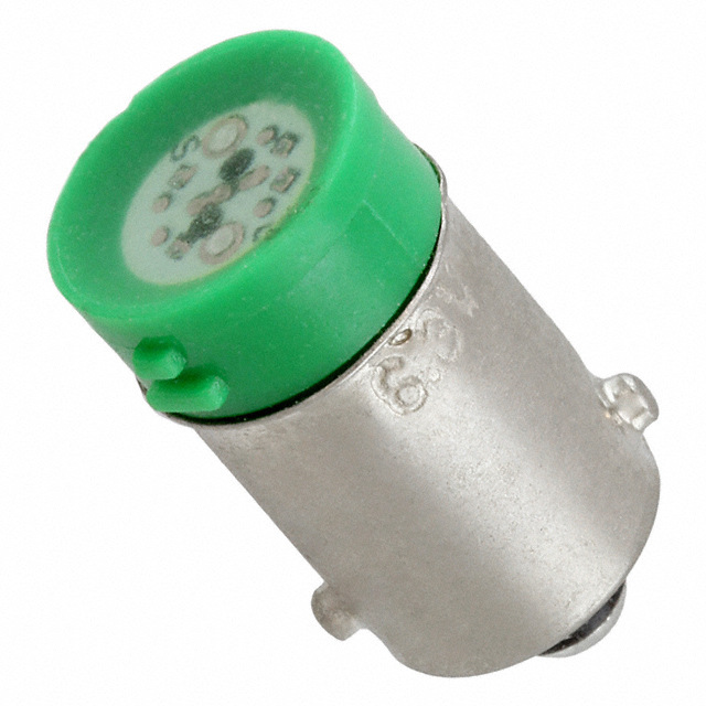
| 描述 | REPL LED BULB GRN 6V |
| 产品分类 | |
| 品牌 | Omron Automation and Safety |
| 数据手册 | http://www.omron.com.au/data_pdf/cat/a22r_m22r_a190-e1-01.pdf?id=3326 |
| 产品图片 |
|
| 产品型号 | A22R-6AG |
| rohs | 无铅 / 符合限制有害物质指令(RoHS)规范要求 |
| 产品系列 | A22RL |
| 其它名称 | A22R-6AG-ND |
| 标准包装 | 1 |
| 特色产品 | http://www.digikey.com/product-highlights/cn/zh/omron-a22r-m22r-pushbutton-switches/1407 |
| 电压 | 6V |
| 类型 | LED |
| 要求 | 开关机壳 |
| 颜色 | 绿 |
| (首先选择,然后应用滤波器)兼容系列 | Omron, A22RL |


- 商务部:美国ITC正式对集成电路等产品启动337调查
- 曝三星4nm工艺存在良率问题 高通将骁龙8 Gen1或转产台积电
- 太阳诱电将投资9.5亿元在常州建新厂生产MLCC 预计2023年完工
- 英特尔发布欧洲新工厂建设计划 深化IDM 2.0 战略
- 台积电先进制程称霸业界 有大客户加持明年业绩稳了
- 达到5530亿美元!SIA预计今年全球半导体销售额将创下新高
- 英特尔拟将自动驾驶子公司Mobileye上市 估值或超500亿美元
- 三星加码芯片和SET,合并消费电子和移动部门,撤换高东真等 CEO
- 三星电子宣布重大人事变动 还合并消费电子和移动部门
- 海关总署:前11个月进口集成电路产品价值2.52万亿元 增长14.8%

PDF Datasheet 数据手册内容提取
Pushbutton Switches/Indicators A22R/M22R series Robust and Graceful design PPuusshhbbuuttttoonn SSwwiittcchheess Push Button Secure and Human-centered This document provides information mainly for selecting suitable models. Please read the document Instruction Sheet carefully for information that the user must understand and accept before purchase, including information on warranty, limitations of liability, and precautions. OMRON Corporation OMRON ELECTRONICS LLC Authorized Distributor: Industrial Automation Company One Commerce Drive Schaumburg, IL 60173-5302 U.S.A. Sensing Devices Division H.Q. Tel: (1) 847-843-7900/Fax: (1) 847-843-7787 Industrial Sensors Division Shiokoji Horikawa, Shimogyo-ku, OMRON ASIA PACIFIC PTE. LTD. Kyoto, 600-8530 Japan No. 438A Alexandra Road # 05-05/08 (Lobby 2), Tel: (81)75-344-7022/Fax: (81)75-344-7107 Alexandra Technopark, Singapore 119967 Tel: (65) 6835-3011/Fax: (65) 6835-2711 Regional Headquarters OMRON (CHINA) CO., LTD. OMRON EUROPE B.V. Room 2211, Bank of China Tower, Wegalaan 67-69-2132 JD Hoofddorp 200 Yin Cheng Zhong Road, © OMRON Corporation 2009 All Rights Reserved. The Netherlands PuDong New Area, Shanghai, 200120, China In the interest of product improvement, Tel: (31)2356-81-300/Fax: (31)2356-81-388 Tel: (86) 21-5037-2222/Fax: (86) 21-5037-2200 specifications are subject to change without notice. Printed in Japan OMRON Industrial Automation Global: www.ia.omron.com Cat. No. A190-E1-01 1009
2 A22R/M22R Series Push Button A22R/M22R Series Push Button 3 hhiigghh ggrraaddee 2 Responds with Round design Soft to the touch vvaarriioouuss nneeeeddss Gentle design for human. illumination to 1 Shining Metal Ring 4 Switch units Provides shining and robust metal ring. 3 Additional unit type 2 Switch units Switch unit can be added. 4 Compact size The body length under a panel decreased by 15% compare with our former products. 15% decrease compare with the 46.8 mm current product
Lighted Type 4 A22R/M22R Series Push Button A22R/M22R Series Push Button 5 Assembled Models Operation Units NNNooonnn---llliiiggghhhttteeeddd TTTyyypppeee LLLiiiggghhhttteeeddd TTTyyypppeee NNNooonnn---llliiiggghhhttteeeddd TTTyyypppeee LLLiiiggghhhttteeeddd TTTyyypppeee Flat type Projection type Projection type Flat type Projection type Projection type A22R-F @ - @ A22R-T @ - @ A22RL-T @ - @ A22R-F @ - @ @ A22R-T @ - @ @ A22RL-T @ - @ - @ @ SSSeeellleeeccctttooorrr NNNooonnn---llliiiggghhhttteeeddd TTTyyypppeee SSSeeellleeeccctttooorrr LLLiiiggghhhttteeeddd TTTyyypppeee SSSeeellleeeccctttooorrr NNNooonnn---llliiiggghhhttteeeddd TTTyyypppeee SSSeeellleeeccctttooorrr LLLiiiggghhhttteeeddd TTTyyypppeee 2 notches 3 notches 2 notches 3 notches A22RS-2 @ A22RS-3 @ A22RW-2 @ @ A22RW-3 @ @ 2 notches 3 notches 2 notches 3 notches A22RS-2 @ - @ A22RS-3 @ - @ A22RW-2 @ @ - @ - @ A22RW-3 @ @ - @ - @ KKKeeeyyy SSSeeellleeeccctttooorrr SSSwwwiiitttccchhh UUUnnniiittt SSSoooccckkkeeettt KKKeeeyyy SSSeeellleeeccctttooorrr TTTyyypppeee IIInnndddiiicccaaatttooorrr EEEmmmeeerrrgggeeennncccyyy SSStttoooppp SSSwwwiiitttccchhh 2 notches 3 notches Switch with Lamp socket Socket A22RK-2 @ A22RK-3 @ A22RL- @ M - @ A22R- @ M SSSwwwiiitttccchhh BBBllloooccckkk LLLaaammmppp SSSoooccckkkeeettt MMMooouuunnntttiiinnnggg PPPlllaaattteee LLLEEEDDD 2 notches 3 notches Indicator *Emergency A22RK-2 @ - @ A22RK-3 @ - @ M22R-E @ - @ A22E- @ - @ - @ - @ * Refer to the Safety Components Series Catalog (Cat. No. Y106) for detail. Switch block Lamp socket Mounting plate LED A22R- @ A22R- @ A22R-3200 A22R - @ @
6 A22R/M22R Series Push Button A22R/M22R Series Push Button 7 Assembled Models Assembled Models PPPuuussshhhbbbuuuttttttooonnn SSSwwwiiitttccchhheeesss SSSeeellleeeccctttooorrr SSSwwwiiitttccchhheeesss ● Non-lighted/Lighted ● Non-lighted/Lighted Pushbutton Pushbutton Contact Number Knob Knob Contact Appearance Part No. Dimensions Appearance Part No. Dimensions shape color form of notch position color form A22R-F@-@@ 1a A22R-FW-10@ 28° A22RS-2@-@ 1a A22RS-2M-10 28° 1a A22R-FB-10@ R27 1a1b A22RS-2M-11 R27 2 notches 1a A22R-FG-10@ 1a A22RS-2A-10 36 1a A22R-FR-10@ 1a1b A22RS-2A-11 36 1a A22R-FY-10@ A22RS-3@-@ 2a A22RS-3M-20 29.8 29.8 Round/Flat 1a A22R-FA-10@ 29.8 2a A22RS-3A-20 29.8 * These Non-lighted types provide black knobs. 11bb AA2222RR--FFBR--0011@@ 10.81060.5 3 notches 24.210 0.5 Insert one of the following letters into the box @. MA:: AMltoemrneantetary 46.8 6 846. A22R-T@-@@ 1a A22R-TW-10@ 1a A22R-TB-10@ 29.8 A22RW-2@@-@-@ 1a A22RW-2MG-24A-10 29.8 23.7 1a A22R-TG-10@ 2 notches 1a1b A22RW-2MR-24A-11 1a A22R-TR-01@ 16.7100.5 AC, DC 24V 1a A22RW-2AY-24A-10 24.210 50. 1a1b A22RW-2AA-24A-11 1a A22R-TY-10@ Projection 6 A22RW-3@@-@-@ 2a A22RW-3MG-24A-20 6 1a A22R-TA-10@ 1b A22R-TB-01@ 46.8 3 notches 2a A22RW-3MR-24A-20 846. AC, DC 24V 2a A22RW-3AY-24A-20 1b A22R-TR-01@ 2a A22RW-3AA-24A-20 Insert one of the following letters into the box @. M: Momentary A: Alternate A22RL-T@-@-@@ 1a A22RL-TW-24A-10@ 1a A22RL-TG-24A-10@ Projection 1a A22RL-TR-24A-10@ AC, DC 24V 29.8 1a A22RL-TY-24A-10@ 23.7 1a A22RL-TA-24A-10@ 716.100.5 1a A22RL-TW-T2-10@ 6 1a A22RL-TG-T2-10@ 1a A22RL-TR-T2-10@ 46.8 Projection 1a A22RL-TY-T2-10@ AC 220V 1a A22RL-TA-T2-10@ Insert one of the following letters into the box @. M: Momentary A: Alternate
8 A22R/M22R Series Key/Signal Indicator/Construction A22R/M22R Series Key/Signal Indicator/Construction 9 Assembled Models Structure SSSeeellleeeccctttooorrr SSSwwwiiitttccchhheeesss AAA222222RRR ssseeerrriiieeesss ● Key Selector Number Key Contact Appearance Part No. Dimensions Pushbutton unit of notch position form A22RK-2@-@ 1a A22RK-2ML-10 28° 1a1b A22RK-2ML-11 R27 1a A22RK-2M-10 2 notches 1a1b A22RK-2M-11 36 1a A22RK-2AL-10 1a1b A22RK-2AL-11 29.8 : key release position 27 LED A22RK-3@-@ 2a A22RK-3ML-20 2a A22RK-3M-20 Lighting source 2a A22RK-3MC-20 19 10 0.5 (cid:129) LED 3 notches 2a A22RK-3AC-20 6 Body unit : key release position 46.8 Contact form (cid:129) 1a,1b Lighting method (cid:129) Non-lighted (cid:129) Without voltage-reduction unit (cid:129) With voltage reduction unit IIInnndddiiicccaaatttooorrr ● All-in-one type MMM222222RRR ssseeerrriiieeesss Indicator Appearance LED rating Part No. Dimensions color M22R-E@-@ M22R-EW-24A 29.8 M22R-EG-24A Indicator AC, DC 24V M22R-ER-24A Lighting source M22R-EY-24A (cid:129) LED M22R-EA-24A 4 M22R-EW-T2 14. 0.5 M22R-EG-T2 6 AC 220V M22R-ER-T2 0.5 4 M22R-EY-T2 M22R-EA-T2
10 A22R/M22R Series Push Button A22R/M22R Series Push Button 11 Individual Unit Individual Unit PPPuuussshhhbbbuuuttttttooonnn uuunnniiittt SSSeeellleeeccctttooorrr uuunnniiittt ● Non-lighted/Lighted ● Non-lighted/Lighted Pushbutton Pushbutton Number Knob Knob Appearance Part No. Dimensions Appearance Part No. Dimensions shape color of notch position color A22R-F@-@ A22R-FW-@ 29.8 A22RS-2@ A22RS-2M 29.8 A22R-FB-@ A22RS-2A A22R-FG-@ 2 notches A22R-FR-@ Round/Flat A22R-FY-@ A22R-FA-@ 810. 10 0.5 A22RS-3@ A22RS-3M 2 Insert one of the following letters into the box @. 6 A22RS-3A 24. M: Momentary 22 10 0.5 A: Alternate 3 notches * These Non-lighted types provide black knobs. 6 2 2 A22R-T@-@ A22R-TW-@ A22R-TB-@ A22R-TG-@ A22RW-2@ A22RW-2MG 7 A22R-TR-@ 16.100.5 A22RW-2MR Projection A22R-TY-@ 6 A22RW-2MY 2 2 A22R-TA-@ 2 notches A22RW-2MA Insert one of the following letters into the box @. Lighted M: Momentary Type A22RW-2AG A: Alternate 2 A22RW-2AR 4. 2 A22RL-T@-@ A22RL-TW-@ A22RW-2AY 10 0.5 A22RL-TG-@ 6 A22RW-2AA 22 LPigrhotjeedc ttioypne AA2222RRLL--TTRY--@@ 716.100.5 A22RW-3@ A22RW-3MG A22RL-TA-@ 226 A22RW-3MR Insert one of the following letters into the box @. 3 notches A22RW-3MY M: Momentary Lighted A: Alternate Type A22RW-3AA A22RW-3AG A22RW-3AR
12 A22R/M22R Series Key/Switch Section/Mounting Console A22R/M22R Series Key/Switch Section/Mounting Console 13 Individual Unit Individual Unit SSSeeellleeeccctttooorrr uuunnniiittt SSSwwwiiitttccchhh /// LLLaaammmppp uuunnniiitttsss ● Key Selector ● Switch unit Number Appearance Unit Contact form Part No. Dimensions Appearance Key position Part No. Dimensions of notch A22R-@ 1a A22R-10 9.8 4 A22RK-2@ A22RK-2ML 29.8 1b A22R-01 5.6 Contact * Additional one block can be mountet to make 2a, 2b, or A22RK-2M block 1a1b. 26.5 23.5 2 notches A22RK-2AL 36 (cid:2): key release position A22RK-3@ A22RK-3ML 7 ● Lamp socket 2 Appearance Unit Rating Part No. Dimensions A22RK-3M A22R-@ Without voltage 10.3 3 notches A22RK-3MC 19100.5 reduction unit A22R-TN AC/DC6V, AC/DC12V, 6.3 1 A22RK-3AC 226 Lamp socket AC/DC24V (cid:2): key release position With voltage 26.5 23.5 reduction unit A22R-T2 9.8 AC220V 36 SSSwwwiiitttccchhh uuunnniiittt ● For Lighted type MMMooouuunnntttiiinnnggg ppplllaaattteee Appearance Type Contact form Part No. Dimensions A22RL-@M-@ 1a A22RL-10M 1b A22RL-01M 29.8 Appearance Unit Part No. Dimensions 10.3 Standard 2a A22RL-20M A22R-3200 28° 2b A22RL-02M 6.3 1a1b A22RL-11M R27 1a A22RL-10M-T2 8 1b A22RL-01M-T2 39. Mounting A22R-3200 AC 220V 2a A22RL-20M-T2 plate 36 2b A22RL-02M-T2 1a1b A22RL-11M-T2 29.8 ● For Non-lighted type Appearance Type Contact form Part No. Dimensions A22R-@M 1a A22R-10M 29.8 1b A22R-01M 5 0. 1 Socket 2a A22R-20M 5 3. 3 1a1b A22R-11M 2b A22R-02M
14 A22R/M22R Series LED/Button/Knob/Key/Signal Indicator A22R/M22R Series LED/Button/Knob/Key/Signal Indicator 15 Individual Unit Nomenclature LLLaaammmppp uuunnniiittt NNNooommmeeennnccclllaaatttuuurrreee ● LED ● Completely Assembled A22R@-@@-@-@@ Pushbutton switches LED operating A22R@ —@@— @—@@ Appearance Lighting color Part No. Dimensions voltage ➀ ➁ ➂ ➃ ➄ ➅ A22R-@@ A22R-6AW ➀ Lighting ➁ Pushbutton Shape ➂ Lighting Color ➃ Light Source ➄ Contact Form ➅ Switch Operation A22R-6AG Code Lighting Code Shape Code Color Operating Contact Code Switch Operation Code Code LED Non- F Flat * R Red Voltage Form M Momentary action A22R-6AR Blank lighted AC/DC6V T Projection G Green Blank No light source 10 1a A Alternate action A22R-6AY L Lighted * For Non-lighted Y Yellow 6A AC/DC6V 01 1b type only W White 12A AC/DC12V 11 1a1b A22R-6AA A Blue 24A AC/DC24V 20 2a A22R-12AW 9.6 B Black * 02 2b ➃ Light Source A22R-12AG BA9S/13 * For Non-lighted LED A22R-12AR 20 type only Code OVpoelrtaatgineg AC/DC12V A22R-12AY T2 AC220V 9.3 Use AC/DC24V LED A22R-12AA A22R-24AW ● Completely Assembled A22R@-@@-@-@ Selector switches A22R-24AG A22R@ —@@— @—@ ➀ ➁➂ ➃ ➄ LED A22R-24AR AC/DC24V ➀ Lighting ➁ Number of Notches/Reset Method➂ Lighting Color ➃ Light Source ➄ Contact Form A22R-24AY Code Lighting Code Specification Code Color Code Operating Voltage Code Contact Form A22R-24AA Non- 2M 2 notches/Manual Blank Black* Blank No-lighted type 10 1a** S lighted 2A 2 notches/Automatic R Red 6A AC/DC6V 01 1b** W Lighted 3M 3 notches/Manual G Green 12A AC/DC12V 11 1a1b 3A 3 notches/Automatic Y Yellow 24A AC/DC24V 20 2a 3 notches/Manual – A Blue 02 2b 3MA left side, Automatic – * Non-lighted type ➃ Light Source ** For models with 2 right side only Code Operating Voltage notches 3 notches/Automatic – 3AM left side, Manual – T2 AC220V right side Use AC/DC24V LED ● Completely Assembled A22RK-@-@ ● Completely Assembled M22R-@@-@ Key selector switches Indicator A22RK—@ —@ M22R—@@— @ ➀ ➁ ➀ ➁ ➂ ➀ Number of Notches/Reset method ➁ Contact Form ➀ Structure ➁ Lighting Color ➂ Light Source Number of notches, Reset Contact Code Type Lighting Operating Code Code Code Code method, Key release position Form All-in- Color Voltage E 2ML 2 notches, Manual, Left 10 1a** one type R Red 12A AC/DC12V 2M 2 notches, Manual, Left and Right 01 1b** G Green 24A AC/DC24V 2AL 2 notches, Automatic, Left 11 1a1b Y Yellow 33MML 33 nnoottcchheess,, MMaannuuaall,, LLeefftt and Right 0220 22ba WA WBhluitee ➂ UVonlittage Reduction 3MC 3 notches, Manual, Center ** For models Operating 3AC 3 notches, Automatic, Center Code with 2 notches Voltage 3 notches, Manual – left, 3MAL Automatic - right, Left T2 AC220V 3 notches, Automatic – 3AMR left, Manual – right, Right
16 A22R/M22R Series Switch Section/ Indicator Section/LED A22R/M22R Series Switch Section/ Indicator Section/LED 17 Individual Unit Nomenclature NNNooommmeeennnccclllaaatttuuurrreee NNNooommmeeennnccclllaaatttuuurrreee ● Individual unit (Pushbutton unit) A22R@-@@-@ Pushbutton switches ● Individual unit (Switch unit) A22R@-@M-@ A22R@ —@@— @ A22R@ —@M—@ ➀ ➁ ➂ ➃ ➀ ➁ ➂ ➃ ➀ Lighting ➁ Pushbutton Shape ➂ Pushbutton Color ➃ Switch Operation ➀ Lighting ➁ Contact Form ➂ Switch Operation ➃ Voltage Reduction Unit Code Lighting Code Pushbutton Shape CodePushbutton Color Code Switch Operation Code Lighting Code Contact Form Code Switch Operation Code Operation Voltage Blank Non-lighted F Flat* R Red M Momentary action Blank Non-lighted 10 1a M Momentary action Blank Non-lighted type L Lighted T Projection G Green A Alternate action L Lighted 01 1b T2 AC220V* *For Non-lighted type only Y Yellow 11 1a1b *Use with an A22R-24@LED W White 20 2a A Blue 02 2b B Black* *For Non-lighted type only ● Individual unit (Selector unit) A22R@-@@ Selector switches ● Individual unit (Switch block) A22R-@ ● Individual unit (Voltage-reduction unit) A22R-@ A22R@ —@@ A22R—@ A22R—@ ➀ ➁ ➂ ➀ ➀ ➀ Lighting ➁ Number of notches, Reset Method ➂ Knob Color ➀ Contact Form ➀ Body unit Code Lighting Code Number of notches, Reset Method Code Color Code Contact Form Code Operating Voltage S Non-lighted 2M 2 notches, Manual Blank Black* 10 1a AC/DC6V, W Lighted 2A 2 notches, Automatic R Red 01 1b TN AC/DC12V, 3M 3 notches, Manual G Green AC/DC24V 3A 3 notches, Automatic Y Yellow T2 AC220V* 3MA 3 notches, Manual – left, Automatic – right A Blue *Use with an A22R-24@LED 3AM 3 notches, Automatic – left, Manual - right *Non-lighted type ● Individual unit (Key selector unit) A22RK-@ Key selector switches ● Individual unit (LED) A22R-@ @ LED A22RK—@ A22R—@@ ➀ ➀ ➁ ➀ Number of notches, Reset Method, Key Release Position ➀ Operating Voltage ➁ Lighting color Code Number of notches, Reset Method, Key Release Position Code Operating Voltage Code Lighting color 2ML 2 notches, Manual, Left 6A AC/DC6V R Red 2M 2 notches, Manual, Left and Right 12A AC/DC12V G Green 2AL 2 notches, Automatic, Left 24A AC/DC24V Y Yellow 3ML 3 notches, Manual, Left W White 3M 3 notches, Manual, Left and Right A Blue 3MC 3 notches, Manual, Center 3AC 3 notches, Automatic, Center 3MAL 3 notches, Manual – left, Automatic – right, Left 3AMR 3 notches, Automatic – left, Manual – right, Right
18 A22R/M22R Series A22R/M22R Series 19 Accessories / Tools Accessories / Tools IIIttteeemmmsss IIIttteeemmmsss ● Accessories ● Accessories Item Appearance Classification Part No. Remarks Item Appearance Classification Part No. Remarks White A22Z-3321 Black A22Z-3443B With Snap-in Legend Red A22Z-3322 Without Red A22Z-3443R Standard Plate (without text) Snap-in Legend Plate is acrylic. text size White A22Z-3443W Black A22Z-3323 Transparent A22Z-3443C Legend Without Snap-in Legend Plate A22Z-3320 Plate White text A22Z-3443R-2 Frames White A22Z-3331 on red With Snap-in Legend background STOP A22Z-3443R-4 Red A22Z-3332 Large Plate (without text) Snap-in Legend plate is acrylic. size │ A22Z-3443B-1 Attached to the Standard Black A22Z-3333 Standard Plate Frame. size START A22Z-3443B-3 Material: Acrylic. Without Snap-in Legend Plate A22Z-3330 ON A22Z-3443B-5 Lock Ring Round A22Z-3360 Tsehceu Lreo clokc Rk infega itsu rues iesd r ewqhueirne dm.ore LPelgaetensd With text White text OFF A22Z-3443B-6 on black Used to prevent dust or water background UP A22Z-3443B-7 For flat models A22Z-3600F from entering the Operation Unit Sealing Caps (Pushbutton, etc.). DOWN A22Z-3443B-8 Color: opaque For projection models A22Z-3600T Material: silicon POWER ON A22Z-3443B-9 Can be plugged into pre-cut panel OFF-ON A22Z-3443B-10 Hole plug Round A22Z-3530 holes for future expansion. The color is black. Black A22Z-3453B One hole A22Z-B101 Red A22Z-3453R Attached to the Large-size Large Without Legend Plate Frame. size text White A22Z-3453W Material: Acrylic. Control Boxes Two holes A22Z-B102 Material: Polycarbonate resin. Transparent A22Z-3453C Three holes A22Z-B103 No print (Round) A22Z-3460 │ A22Z-3460-1 After printing on a film, affix to the indicator Plate of ø7~9 A22Z-3500-1 Applicable Plastic connector used to extend Character Films Character A22Z-3460-2 the Lighted Pushbotton Switch. Connectors diameter a cable from the Switch Box. Print (The back is coated with (mm) (See page 30) (Round) START A22Z-3460-3 adhesive.) ø9~11 A22Z-3500-2 STOP A22Z-3460-4 ● Tools Item Appearance Part No. Remarks Lamp Extractor A22Z-3901 Rubber tool used to easily replace Lamps. Tightening wrench A22Z-3905 Tool used to tighten nuts from the back of the panel.
20 A22R/M22R Series A22R/M22R Series 21 Specifications Characteristics AAApppppprrrooovvveeeddd ssstttaaannndddaaarrrdddsss CCChhhaaarrraaacccttteeerrriiissstttiiicccsss ● Switch unit ● Environment UL 508/CSA C22.2 No.14 Non-lighted type: -20 to +60ºC Ambient temperature*1 UL, cUL File No. E76675 Lighted type: -20 to +50ºC 6A 240VAC/10A 120VAC EN EN60947-5-1 (low voltage directive) 3A 240VAC (AC-15) Ambient humidity -35 to 85%RH CCC GB/14048.5-2001 Storage temperature*1 -40 to +70ºC 3A 240VAC/1.5A 24VDC ● Lamp unit Protective code*2 IP65 UL 508/CSA C22.2 No.14 UL, cUL File No. E76675 Vibration resistance 10 to 55Hz, Double amplitude 1.5mm 24VAC/DC MAX Non-lighted type: 1,000m/s2 ● Voltage-reduction unit Shock resistance Lighted type: 600m/s2 UL 508/CSA C22.2 No.14 *1: With no icing or condensation UL, cUL File No. E76675 *2: Protection against dust or water from the front of a mounting panel side 220VAC GB/14048.5-2001 CCC ● Operation 220VAC ● Indicator Operation Slow action UL 508/CSA C22.2 No.14 Mechanical Momentary operation: 60 operations/minute max. File No. E76675 Operating UL, cUL 12A: 12VAC/DC frequency Electrical Knob-type and Key-type selector: 30 operations/minute max. 24A: 24VAC/DC T2 : 220VAC Momentary switch :3,000,000 operations CCC GB/14048.5-2001 Mechanical durability Alternate, Key/Knob Selector switches: 300,000 operations T2 : 220VAC RRRaaatttiiinnngggsss ● Electrical Characteristics (Switch block) ● Contacts Insulation resistance 100MΩ Minimum (At 500VDC) Rated current Rated voltage Inductive load (A) (V) Rated current (A) Power facfor Between terminals of same polarity: AC2,500V 50/60Hz for 1 minute Dielectric strength 10 240 3 0.4 Between terminals of different polarity: AC2,500V 50/60Hz for 1 minute Rated current values are determined according to the testing conditions. The above ratings were obtained by conducting tests under the following Rating AC-15, A600, Ue=240V, Ie=3A conditions: Ambient temperature: 20+/- 2ºC Ambient humidity: 65+/-5%RH Rated insulation voltage Ui=600V, Pollution degree: 3 Operating frequency: 30 operations/minute Conditional short-circuit current 10A, IEC60209-1 ● LED (For pushbutton unit) Operating voltage Current consumption Electrical durability 500,000 operations Minimum (at AC 240V, 3A, cosø=0.4) AC/DC 6V±5% 20mA AC/DC 12V±5% 20mA AC/DC 24V±5% 20mA ● LED (For indicator unit) Operating voltage Current consumption AC/DC 12V±5% 20mA AC/DC 24V±5% 20mA ● Voltage reduction unit (For pushbutton and indicator units) Operating voltage Current consumption AC 200V(190 to 230V) 20mA
22 A22R/M22R Series A22R/M22R Series 23 Characteristics Terminal OOOpppeeerrraaatttiiinnnggg ccchhhaaarrraaacccttteeerrriiissstttiiicccsss TTTeeerrrmmmiiinnnaaalll AAArrrrrraaannngggeeemmmeeennnttt ● Pushbutton switch (1a1b) ● Bottom view (unit: mm) No-lighted (1a1b) Lighted Indicator Total Travel Force (TTF) 29.4N Maximum 19.8 9.9 Total Travel (TT) 5.5mm Maximum Switch Block 10.1 ● Knob-type selector switch (1a1b) Manual reset: 0.34N·m Maximum * 20.2 26.2 Total Travel Force (TTF) Auto-reset 2-notch: 0.25N·m * 3-notch: 0.34N·m * Total Travel (TT) 2-notch: approx. 90 degree (3-notch: approx.45 degree) M3.5±Screw Switch Blocks Lamp Socket Releasing Force (RF) Manual reset: 0.34N·m Maximum * TTTeeerrrmmmiiinnnaaalll cccooonnnnnneeeccctttiiiooonnn * Rotation torque for knob type/key type selector switches. ● Key-type selector switch (1a1b) Type Terminal connection Manual reset: 0.34N·m Maximum * Total Travel Force (TTF) Auto-reset 2-notch: 0.25N·m * BOTTOM VIEW 3-notch: 0.34N·m * 1 3 Total Travel (TT) 2-notch: approx. 90 degree (3-notch: approx.45 degree) Non-lighted (1a1b) Releasing Force (RF) Manual reset: 0.34N·m Maximum * 2 4 * Rotation torque for knob type/key type selector switches. BOTTOM VIEW 1 X1 3 Lighted without voltage reduction unit (1a1b) x 2 X2 4 * LED: For AC/DC BOTTOM VIEW 1 X1 3 Lighted with voltage reduction unit (1a1b) x 2 X2 4
24 A22R/M22R Series A22R/M22R Series 25 Precautions Precautions PPPrrreeecccaaauuutttiiiooonnnsss PPPrrreeecccaaauuutttiiiooonnnsss ● Operational Environment ● Switching ● Mechanical Conditions Warning (cid:129) The IP65 model is designed with a degree of protection so that it will not (cid:129) Do not use the Switch for loads that exceed the rated (cid:129) Operating the Switch using a hard object (e.g., metal), or with sustain damage if it is subject to water from any direction to front of the panel. switching capacity or other contact ratings. Doing so may a large or sudden force, may deform or damage the Switch, Do not wire and/or touch the switch (cid:129) This Switch is indoor use only. Outdoor use of the Switch will cause result in contact weld, separation failure, or insulation failures. resulting in faulty or rough operation, or shortening of the terminal while power is supplied to (cid:129) oDpoe nraotti ouns efa tihluer eS owfi ttchhe inS wthitec hw.ater, oil, or in locations where water, oils, Furthermore, the Switch may be broken or damaged. Switch life. the switch to avoid electric shock. detergent, chemicals, or solvent is applied to the Switch always. (cid:129) Do not touch the charged switch terminals while power is Otherwise, switching failure will be happened. supplied, otherwise an electric shock may be received. (cid:129) Do not use the Switch under the environmental condition where corrosive (cid:129) The life of the Switch varies greatly with switching conditions. Hammer gas (ammonia, chlorine, dioxide sulfur…etc.) is generated. Otherwise, Before using the Switch, be sure to test the Switch under the Switch will corrode. (cid:129) Do not use the Switch in locations where dust, metal or plastic dust exists. actual conditions. Make sure that the number of switching Do not apply excessive Correct Use Dust will accumulate o the Switch, and then the Switch wouldn’t operate operations is within the permissible range. or sudden force. normally. If a deteriorated Switch is used continuously, insulation (cid:129) Do not use the Switch under the environmental condition where excessive ● Mounting vibration or shock exists. Otherwise, incorrect switching would occur. failures, contact weld, contact failures, switch damage, or switch burnout may result. (cid:129) Always make sure that the power is turned OFF before ● Electrical Conditions (cid:129) Do not apply excessive or incorrect voltages to the Switch or mounting, removing, or wiring the Switch, or performing (cid:129) The switching load capacity of the Switch greatly varies between AC and incorrectly wire the terminals. Otherwise, the Switch may not maintenance. DC. Always be sure to apply the rated load. The control capacity will function properly and have an adverse effect on external (cid:129) The pushbutton surface is composed of resin. Therefore, do (cid:129) Do not tighten the mounting ring more than necessary using drastically drop if it is a DC load. This is because a DC load has no current tools such as pointed-nose pliers. Doing so will damage the zero-cross point, unlike an AC load. Therefore, if an arc is generated, it circuitry. not attempt to operate the pushbutton using a sharp object, may continue for a comparatively long time. Furthermore, the current Furthermore, the Switch itself may become damaged or burnt. such as a screwdriver or a pair of tweezers. Also, do not mounting ring. The tightening torque is 0.98 to 1.96N·m. direction is always the same, which results in a contact relocation (cid:129) Do not use the Switch in locations where flammable or drop, throw, or knock the Switch. Doing so may damage or (cid:129) Recommended panel thickness: 1 to 5 mm. phenomena whereby the contacts easily stick to each other and do not explosive gasses are present. Otherwise switching arcs or deform the pushbutton surface and result in faulty operation. separate when the surfaces of the contacts are uneven. ● Wiring (cid:129) Some types of load have a great difference between normal current and heat radiation may cause a fire or explosion. (cid:129) Terminal screws must be Phillips with a square washer. inrush current. Make sure that the inrush current is within the permissible (cid:129) Do not drop or disassemble the Switch, otherwise it may not (cid:129) The tightening torque is 1.08 to 1.27N·m. value. The greater the inrush current in the closed circuit is, the greater be capable of full performance. Furthermore, it may be broken the contact abrasion or shift will be. Consequently, contact weld, contact (cid:129) Single wires, stranded wires and crimp terminals except round separation failures, or insulation failures may result. Furthermore, the or burnt. Do not use sharp objects. type can be connected to the Switch. Switch may be broken or damaged. ● LED (cid:129) Applicable Wire Size (cid:129) If the load is inductive, counter-electromotive voltage will be generated. Strand wire: 2mm2 Maximum The higher the voltage is, the higher the generated energy will be, which (cid:129) The LED current-limiting resistor is built-in, so internal Screwdriver increase the abrasion of the contacts and contact relocation phenomena. resistance is not required. Solid wire: 1.6mm diameter Maximum Be sure to use the Switch within the rated conditions. (cid:129) If commercially available LEDs are used, select the ones that Bare Crimp Terminals (AI) meet the following conditions: Tweezers 8mm max. Solenoid Base: BA9S/13@ (Approximately 10 to 20 times higher) Overall length: 26mm Maximum 16.0mm max. I(nAcpapnrodxeismcaetnetl yla mp Power consumption: 2.6 W Maximum (cid:129) Periodic maintenance is required to use the Switch stably. 10 to 15 times higher) i ● Storage Crimp Terminal with Insulating Sheath (Current) M(5A otpotpo 1rro0x tiimmaetse ly (cid:129) When the Switch is left unused or stored for long periods, the higher) 8mm max. R(Aeplapyroximately ambient conditions can have a great effect on the condition of 4 to 5 times higher) the Switch. In certain environments, leaving the Switch exposed may result I deterioration (i.e., oxidation, or the 20.2mm max. o creation of an oxide film) of the contacts and terminals, (Steady current) causing the contact resistance to increase, and making it (cid:129) Secure appropriate insulation distance after wiring of the Switch. (Time) t (cid:129) Before using the Switch, be sure to test the Switch under actual conditions. difficult to solder the lead wires. Therefore, store in a (cid:129) Perform wiring so that the lead wires will not be caught on (cid:129) This product is a standard load type Switch. Using the Switch for opening well-ventilated room, inside, for example, a non-hygroscopic other objects as this will cause stress on the Switch terminals. and closing a microload circuit may cause contact failure. Use the Switch case, in a location where no corrosive gasses are present. Wire the Switch so that there is slack in the lead wires and fix within the operating range as shown in below chart. (cid:129) If the Switch is stored in a location where it will be exposed to lead wires at intermediate points. If the panel to which the Smwaiitncthe nisa nmcoeu pnuterpdo nseee, dpse rtfoo rbme wopireinnge ds oa nthda ct ltohsee odp feonr ing and Voltage (V)30 0.16mA 1.6mA 100mA edTxihrpeeocrets feloigdrhe tt,o, d cdooir lenocorett dlsig trohertse.i nth ien Sthwei tccohl oI rleodc aptliaotnes m wahye rfaed ite w. ill be closing of the panel will not interfere with the wiring. 24 Microload Standard area load area 12 Invalid area 5 1mA 10mA 0 0.1 1 10 100 1,000 Current (mA) (cid:129) When use the Switch for opening and closing a microload or large-load, use the Switch with an appropriate relay.
A22R/M22R Series A22R/M22R Series Installation Installation MMMooouuunnntttiiinnnggg tttooo ttthhheee PPPaaannneeelll HHHooowww tttooo cccooonnnfffiiirrrmmm ttthhheee LLLeeevvveeerrr PPPooosssiiitttiiiooonnn,,, OOOPPPEEENNN ooorrr LLLOOOCCCKKK ● The Lever Position, OPEN (Operation unit is not fixed)/LOCK (Operation unit is fixed), can be confirmed from the Switch ➀ Panel Hole Dimensions ➂ Mounting the Operation Unit on the Panel terminal side. (cid:129) The cutout dimensions are as shown in below: (cid:129) Insert the Operation Unit (Pushbutton, etc.) from the front surface of the panel, insert the Lock Ring and the mounting nut from the terminal side, then tighten the nut. Before tightening, check that the rubber washer is present between the Pushbutton Unit and the panel. (cid:129) When using a Legend Plate Frame, put one rubber washer each between the Legend Plate Frame and the panel and between the Operation Unit and the Legend Plate Frame. (One rubber washer will be provided when one Legend Plate Left side Right side Frame is ordered.) In case that no switch block (cid:129) Align the Lock Ring with the groove in the casing, then insert is mounted on the mounting the Lock Ring so that its edge is located on the panel side. plate No.1. (cid:129) Tighten the mounting nut at a torque of 0.98 to 1.96N·m. Two One (cid:129) When using a Lock Ring, replace with the supplied Lock Ring, holes hole When Lock Ring When Lock Ring insert the projecting part into the lock slot, and then tighten the is not used. is used. mounting nut. (cid:129) Recommended panel thickness is 1 to 5mm. Rubber washer Panel Hold here (cid:129) In outer surface treatment such as coating is performed for Mounting nut (OPEN condition) (LOCK condition) the panel, the panel dimensions after outer surface treatment Panel Projection part must meet the specified panel dimensions. ➁ Matrix Installation (1) The following panel hole (2) The following panel hole dimensions apply when dimensions apply when the Switch Unit and the Large-size Legend Plate Standard-size Legend Frame is mounted, and Lock Ring Plate Frame and Lock when crimp terminals are Panel Rleiandg wariree sm aoruen cteodn,n aencdte d cBoloncnke tcetermd itnoa tlsh.e Switch ➃ Mounting the Switch on the Pushbutton Unit In case that a switch block Left side Right side directly to the Switch Block. (cid:129) Insert the Pushbutton Unit into the Switch Unit, aligning the is mounted on the mounting arrow mark inscribed on the Case with the lever on the Switch plate No.1. Blocks, then move the lever in the direction indicated by the Hole is Two arrow in the following figure. not shown holes Operation Unit Arrow mark 45 min. Lever (OPEN condition) (LOCK condition) ➄ Removing the Switch (cid:129) Move the lever in the direction indicated by the arrow in the Type of crimp terminal Dimension A following figure, then pull the Pushbutton Unit or the Switch Bare crimp terminals 51 mm Minimum Blocks. In case that a switch block (cid:129) Since the lever has a hole with an inside diameter of 6.5mm, Crimp terminals with insulating sheath 60 mm Minimum is mounted on the mounting the lever can be moved in the specified direction by inserting plate No.1 and an indicator a screwdriver into the hole and then moving the screwdriver. Left side Right side Note: The above dimensions are the minimum dimensions for unit is mounted on the when the wires described under “Applicable Wire Size”. Screwdriver mounting plate No.2. If a different wires are used, the wiring dimensions may One be different so determine an appropriate pitch before Hole is hole setup. not shown (OPEN condition) (LOCK condition)
28 A22R/M22R Series A22R/M22R Series 29 Installation Installation MMMooouuunnntttiiinnnggg///RRReeeppplllaaaccciiinnnggg ttthhheee CCCooolllooorrr CCCaaappp MMMooouuunnntttiiinnnggg///RRReeeppplllaaaccciiinnnggg ttthhheee SSSwwwiiitttccchhh UUUnnniiittt aaannnddd IIInnndddiiicccaaatttooorrr UUUnnniiittt Projection type ➀ Installing the Switch Blocks ➁ Removing the Switch Base (cid:129) Grip and rotate the Color Cap with your fingers. (cid:129) Mount the Unit according to the indicate numbers on the (cid:129) Insert a screwdriver between the Mounting Latch and the Mounting Plate. Switch Block, then push down the screwdriver in the direction indicated by the arrow in the following figure. No. on the Mounting Plate Use the following screwdrivers. m Flat-head mu screwdriver Maxi m m 3 Switch Unit (A22R-10/A22R-01) AAAsssssseeemmmbbbllliiinnnggg ttthhheee CCCaaappp Indicator Unit (A22R-TN/A22R-T2) ➀ Projection type Lighted Pushbutton Switch ➁ Indicator (cid:129) Hook the small protrusion on (cid:129) One more Switch Block can (cid:129) Mount the Color Cap so that the protrusions inside the cap fit (cid:129) Mount the Color Cap so that the protrusions inside the the Switch Block into the groove be mounted. into the grooves in the Pushbutton Unit. Pushbutton Unit fit into the grooves in the cap. on the Mounting Latch on the other side of the lever, then push up the Switch Block in the direction indicated by the arrow Protrusion part in the figure below: Protrusion parts Grooves on the Cap Reflector Mounting Lever Latch Color Cap Color Cap Protrusion Switch Block IIInnnssstttaaalllllliiinnnggg///RRReeeppplllaaaccciiinnnggg ttthhheee LLLEEEDDD Protrusion ➀ Installing/Replacing from the Panel Surface ➁ Installing/Replacing on the Switch Switch Block Note: In case that two Switch Block (cid:129) Insert the Lamp Extractor(A22Z-3901) into the lamp, then rotate (cid:129) Grip the lamp with your fingers, then rotate the lamp while are mounted, a Control Box the Extractor while pressing it. pressing it against the Switch. cannot be used.
30 A22R/M22R Series A22R/M22R Series 31 Installation Installation CCCooonnntttrrrooolll BBBoooxxx EEEnnngggrrraaavvviiinnnggg MMMooouuunnntttiiinnnggg aaannnddd DDDiiisssmmmooouuunnntttiiinnnggg SSSnnnaaappp---iiinnn LLLeeegggeeennnddd ➀ Mounting the Switch ➁ Creating a Cable Port Hole (cid:129) Engrave the characters on the surface on the Cap. Make sure that (cid:129) Press and secure the Snap-in Legend Plate onto the Legend Plate The Standard-size Legend Plate Frame can be mounted. Place the tip of a screwdriver on the surface where the cable the characters are aligned parallel to the imaginary lie connecting Frame. the two protruding portions to the left and right of the Cap. (cid:129) The direction of the characters will vary with the mounting direction Mount the Switch in the same way as for an ordinary panel. port hole is to be created with the cover attached and strike the (cid:129) The characters must not be engraved deeper than 0.5mm. Apply an of the control panel if the Switch is a knob or key selector model. screwdriver to punch a hole. Attempts to punch a hole on the alcohol-based paint coating, such as melamine, alkyd, or acrylic Snap-in Legend Plate other side of the case will damage the Box. resin paint coating, to the engraved characters. Legend Plate Frame Protruding portions of the Cap Screwdriver Side Snap-in Legend Plate Switch box Cover Cable port hole Concave surface (cid:129) To easily remove the Snap-in Legend Plate from the Legend Plate Strike the Frame mounted to the panel. Insert a Tool with a thin tip into the screwdriver to punch a hole Material: Acrylic space between the Snap-in Legend Plate and the Legend Plate Groove by place 4 parts Frame. (cid:129) Engrave the characters directly on the matted side of the Snap-in diagonally. Legend Plate. ➂ Securing the Connector Cable (cid:129) The characters must be engraved no deeper than 0.5mm. (cid:129) Apply alcohol-based paint coating to the engraved characters. ➀ Insert the connector into the cable port in the Box and secure with the fixing nut inside the box. (cid:129) If the Snap-in Legend Plate is transparent, engrave the mirror-written ➁ Open a hole in the thin rubber section of the rubber ring. characters on the back of the Snap-in Legend Plate and apply paint ➂ Pass the tightening cap through the cable, insert the cable into the connector, and tighten the hexagonal nut to secure the cable. coating of a different color to the remaining part of the Snap-in Legend Plate. Fixing nut Rubber washer Cable diameter (mm) Connector AAAffffffiiixxxiiinnnggg CCChhhaaarrraaacccttteeerrr FFFiiilllmmm 7 to 9 mm dia. A22Z-3500-1 (cid:129) The Snap-in Legend Plate is easily removed by pressing the Connector Tightening cap (cid:129) Hold the Cap, remove the cardboard o the Film, and attach the Film Snap-I Legend Plate from the back of the Legend Plate Frame. 9 to 11 mm dia. A22Z-3500-2 to the Cap. Make sure that the protruding portions of the Cap engage (cid:129) The Legend Plate Frame is made of acrylic resin, which is easily Cable the cutout portions of the Film and that the characters are aligned damaged by shock. Be sure to handle the Legend Plate Frame parallel to the imaginary line connecting the two protruding portions with care. to the left and right of the Cap. Remove the cardboard. Inside Outside Box Protruding portions on Cap PPPrrreeecccaaauuutttiiiooonnnsss wwwhhheeennn uuussseee ttthhheee IIInnndddiiicccaaatttooorrrsss (cid:129) Lock Ring (A22Z-3360) cannot be used. (cid:129) When use the Control Box (A22Z-B10@), cut the (cid:129) When use the Legend Plate Frames projection portions shown in the below fig. (A22Z-332@, A22Z-333@) cut the projection portions shown in the below fig. Cut the projection portions Cut the projection portions