ICGOO在线商城 > 9104-12-10
- 型号: 9104-12-10
- 制造商: Coto Technology
- 库位|库存: xxxx|xxxx
- 要求:
| 数量阶梯 | 香港交货 | 国内含税 |
| +xxxx | $xxxx | ¥xxxx |
查看当月历史价格
查看今年历史价格
9104-12-10产品简介:
ICGOO电子元器件商城为您提供9104-12-10由Coto Technology设计生产,在icgoo商城现货销售,并且可以通过原厂、代理商等渠道进行代购。 提供9104-12-10价格参考¥44.77-¥76.73以及Coto Technology9104-12-10封装/规格参数等产品信息。 你可以下载9104-12-10参考资料、Datasheet数据手册功能说明书, 资料中有9104-12-10详细功能的应用电路图电压和使用方法及教程。
| 参数 | 数值 |
| 产品目录 | |
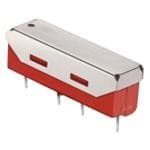
| 描述 | RELAY REED SPST 500MA 12V簧片继电器 1FA HV 12V MAG SH |
| 产品分类 | |
| 品牌 | Coto Technology |
| 产品手册 | |
| 产品图片 |
|
| rohs | 符合RoHS无铅 / 符合限制有害物质指令(RoHS)规范要求 |
| 产品系列 | 簧片继电器,Coto Technology 9104-12-109104 |
| mouser_ship_limit | 该产品可能需要其他文件才能进口到中国。 |
| 数据手册 | |
| 产品型号 | 9104-12-10 |
| 产品目录绘图 |
|
| 产品目录页面 | |
| 产品种类 | 簧片继电器 |
| 关闭电压(最小值) | 1 VDC |
| 其它名称 | 12/10/9104 |
| 包装 | 散装 |
| 商标 | Coto Technology |
| 外观尺寸或封装类型 | SIP |
| 安装类型 | 通孔 |
| 导通电压(最大值) | 9 VDC |
| 工作时间 | 0.75ms |
| 工作温度 | -20°C ~ 85°C |
| 工厂包装数量 | 18 |
| 应用说明 | |
| 开关电压 | 1000VAC,1000VDC - 最小值 |
| 最大开关功率 | 10 W |
| 标准包装 | 18 |
| 特性 | 磁屏蔽 |
| 端子类型 | PC 引脚 |
| 类型 | SIP Reed Relays, High Voltage |
| 系列 | 9104 |
| 线圈功率 | - |
| 线圈抑制二极管 | No |
| 线圈电压 | 12VDC |
| 线圈电流 | 24mA |
| 线圈电阻 | 500 欧姆 |
| 线圈类型 | 无锁存 |
| 继电器类型 | 舌簧 |
| 触头外形 | SPST-NO(1 A 型) |
| 触头材料 | - |
| 触点形式 | 1 Form A (SPST-NO) |
| 触点材料 | Ruthenium |
| 释放时间 | 0.5ms |
| 额定接触(电流) | 500mA |




- 商务部:美国ITC正式对集成电路等产品启动337调查
- 曝三星4nm工艺存在良率问题 高通将骁龙8 Gen1或转产台积电
- 太阳诱电将投资9.5亿元在常州建新厂生产MLCC 预计2023年完工
- 英特尔发布欧洲新工厂建设计划 深化IDM 2.0 战略
- 台积电先进制程称霸业界 有大客户加持明年业绩稳了
- 达到5530亿美元!SIA预计今年全球半导体销售额将创下新高
- 英特尔拟将自动驾驶子公司Mobileye上市 估值或超500亿美元
- 三星加码芯片和SET,合并消费电子和移动部门,撤换高东真等 CEO
- 三星电子宣布重大人事变动 还合并消费电子和移动部门
- 海关总署:前11个月进口集成电路产品价值2.52万亿元 增长14.8%

PDF Datasheet 数据手册内容提取
9104 SERIES/HIGH VOLTAGE SIP REED RELAYS 9104 Series Hi Voltage SIP Reed Relays Molded SIP relays are the industry standard when high reliability and consistent performance are desired in a compact package. The 9104 Series adds high voltage switching capability and high voltage standoff capability to a SIP relay package. These high voltage, high performance relays are ideally suited for Automatic Test Equipment, Instrumentation, Battery Management, Solar and Process Control applications where voltage isolation is a key design requirement. 9104 Series Features uHigh voltage switching up to 1000 V uHigh dielectric strength (up to 4000 V DC) uHigh Insulation Resistance – 1011Ω minimum uHigh reliability, hermetically sealed contacts for long life uHigh speed switching compared to electromechanical relays uMolded thermoset body on integral lead frame design uOptional Coil Suppression Diode – protects coil drive circuits uMagnetic Shield – reduces interaction uUL File #E67117 - Contact factory for details uRoHS compliant DIMENSIONS in Inches (Millimeters) TOP VIEW PIN #1 .950 Max. (24.13) .154 Typ. .245 Max. (3.9) (6.22) .103 Typ. (2.6) .320 Max. .020 Typ. (8.13) .(.51) .120 (3.0) 1 3 5 7 .018 Typ. .125 ± .005 (.46) (3.17 ± .13) .010 Typ. (.25) .300 .200 .300 (7.62) (5.08) (7.62) Ordering Information Part Number 9XXX-XX-XX General Options Model Number 0=No Diode 9104 1=Diode2 Coil Voltage Dielectric Contacts 05=5 volts 12=12 volts Strength (Min) Shield to Coil 1=2000/3000 3=3000/3000 4=4000/4000 08242018 tteell:: ((440011)) 994433..22668866 || ffaaxx:: ((440011)) 994422..00992200
MODEL NUMBER 91042 Parameters Test Conditions Units 4 Pin SIP COIL SPECS. Nom. Coil Voltage VDC 5 12 5 12 Max. Coil Voltage VDC 6.5 15.0 6.5 15.0 Coil Resistance +/- 10%, 25° C Ω 175 500 140 500 Operate Voltage Must Operate by VDC - Max. 3.75 9.0 3.75 9.0 Release Voltage Must Release by VDC - Min. 0.5 1.0 0.5 1.0 CONTACT RATINGS Switching Voltage3 Max DC/Peak AC Resist. Volts 1000 Switching Current Max DC/Peak AC Resist. Amps 0.5 Carry Current Max DC/Peak AC Resist. Amps 1.3 Contact Rating Max DC/Peak AC Resist. Watts 10 Life Expectancy-Typical1 Signal Level 1.0V, 10mA x 106 Ops. 300 Static Contact 50mV, 10mA Ω 0.150 Resistance (max. init.) Dynamic Contact 0.5V, 50mA Ω 0.200 Resistance (max. init.) at 100 Hz, 1.5 msec RELAY SPECIFICATIONS Insulation Resistance Between all Isolated Pins Ω 1011 (minimum) at 100V, 25°C, 40% RH Capacitance - Typical No Shield pF 1.0 Across Open Contacts Open Contact to Coil No Shield pF - Dielectric Strength4 Between Contacts VDC/peak AC 2000 / 3000 4000 (minimum) Contacts/Shield to Coil VDC/peak AC 2000 / 3000 4000 Operate Time - At Nominal Coil Voltage, msec. 0.75 including bounce - Typical 30 Hz Square Wave Release Time - Typical msec. 0.5 Top View: 1 Dot stamped on top of relay refers to pin #1 location Grid = .1”x.1” (2.54mm x 2.54mm) 3 5 Notes: 1 Consult factory for life expectancy at other switching loads. 7 2 Optional diode is connected to pin #3(+) and pin #5(-). Correct coil polarity must be observed. 3 Switch current limited to 1.0mA @ 1000V. 4 Dielectric Strength 9104-XX-1X 9104-XX-3X 9104-XX-4X VDC/peak AC 2000/3000 3000/3000 4000/4000 Environmental Ratings: Storage Temp: -35°C to +100°C; Operating Temp: -20°C to +85°C; Solder Temp: 270°C max; 10 sec. max All electrical parameters measured at 25°C unless otherwise specified. Vibration: 20 G’s to 2000 Hz; Shock: 50 G’s 08242018 FFoorr mmoosstt rreecceenntt ddaattaa vviissiitt wwwwww..ccoottoorreellaayy..ccoomm CCOOTTOO TTEECCHHNNOOLLOOGGYY,, IINNCC..
 Datasheet下载


