
 Datasheet下载
- 型号: 90J200E
- 制造商: Ohmite
- 库位|库存: xxxx|xxxx
- 要求:
| 数量阶梯 | 香港交货 | 国内含税 |
| +xxxx | $xxxx | ¥xxxx |
查看当月历史价格
查看今年历史价格
90J200E产品简介:
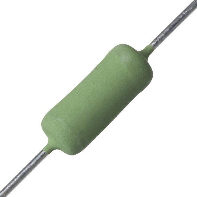
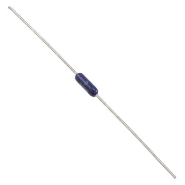
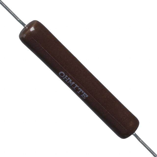
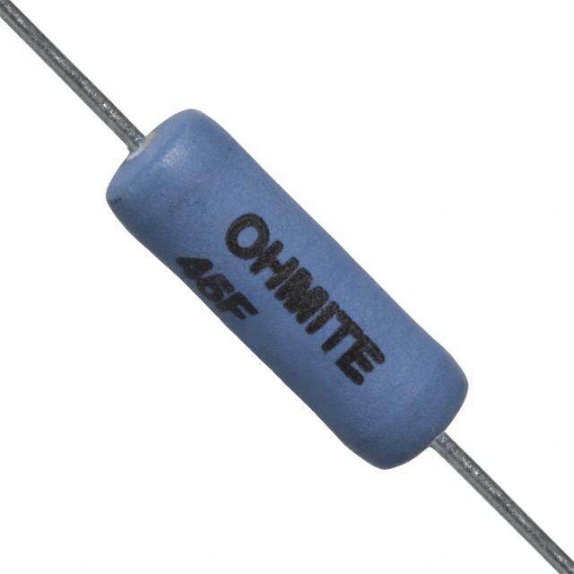
ICGOO电子元器件商城为您提供90J200E由Ohmite设计生产,在icgoo商城现货销售,并且可以通过原厂、代理商等渠道进行代购。 90J200E价格参考¥28.22-¥42.23。Ohmite90J200E封装/规格:通孔电阻器, 200 Ohms ±5% 11W 轴向 通孔电阻器 阻燃涂层,安全 绕线。您可以下载90J200E参考资料、Datasheet数据手册功能说明书,资料中有90J200E 详细功能的应用电路图电压和使用方法及教程。
| 参数 | 数值 |
| 产品目录 | |
| 描述 | RES 200 OHM 11W 5% AXIAL线绕电阻器 - 透孔 11watt 200ohm 5% Axial |
| 产品分类 | |
| 品牌 | Ohmite |
| 产品手册 | |
| 产品图片 | |
| rohs | 符合RoHS无铅 / 符合限制有害物质指令(RoHS)规范要求 |
| 产品系列 | 线绕电阻器,线绕电阻器 - 透孔,Ohmite 90J200E90 |
| 数据手册 | |
| 产品型号 | 90J200E |
| 产品 | Power Resistors Wirewound Vitreous Enamel |
| 产品种类 | 线绕电阻器 - 透孔 |
| 供应商器件封装 | 轴向 |
| 其它名称 | OH90J200E |
| 功率(W) | 11W |
| 功率额定值 | 11 W |
| 包装 | 散装 |
| 商标 | Ohmite |
| 外壳直径 | 8.7 mm |
| 外壳长度 | 45.6 mm |
| 大小/尺寸 | 0.343" 直径 x 1.811" 长(8.70mm x 46.00mm) |
| 容差 | 5 % |
| 封装 | Bulk |
| 封装/外壳 | 轴向 |
| 工作温度范围 | + 25 C to + 350 C |
| 工厂包装数量 | 5 |
| 成分 | 绕线 |
| 标准包装 | 5 |
| 温度系数 | 30 PPM / C |
| 特性 | 阻燃涂层 |
| 电压额定值 | 1.08 kV |
| 电阻 | 200 Ohms |
| 电阻(Ω) | 200 |
| 相关产品 | /product-detail/zh/5908E/5908E-ND/4296346/product-detail/zh/5908/5908-ND/4295133 |
| 端子数 | 2 |
| 端接类型 | Axial |
| 类型 | Axial Lead Wirewound Resistor |
| 系列 | 90 |
| 高度 | - |


- 商务部:美国ITC正式对集成电路等产品启动337调查
- 曝三星4nm工艺存在良率问题 高通将骁龙8 Gen1或转产台积电
- 太阳诱电将投资9.5亿元在常州建新厂生产MLCC 预计2023年完工
- 英特尔发布欧洲新工厂建设计划 深化IDM 2.0 战略
- 台积电先进制程称霸业界 有大客户加持明年业绩稳了
- 达到5530亿美元!SIA预计今年全球半导体销售额将创下新高
- 英特尔拟将自动驾驶子公司Mobileye上市 估值或超500亿美元
- 三星加码芯片和SET,合并消费电子和移动部门,撤换高东真等 CEO
- 三星电子宣布重大人事变动 还合并消费电子和移动部门
- 海关总署:前11个月进口集成电路产品价值2.52万亿元 增长14.8%

PDF Datasheet 数据手册内容提取
90 Series Lead Free Vitreous Enamel Molded Axial Term. Wirewound, 5% Tolerance Standard When you need the highest quality wirewound axial FeatureS terminal resistors available, choose Ohmite’s 90 • Molded Construction provides consistent shape Series resistors. and size (Permits mounting in clips which extends They are manufactured by a unique process that power rating). molds the vitreous enamel over the resistive ele- • Meets MIL-R-26 requirements for insulated resis- ment, helping to ensure consistent dimensions. tors. This uniformity permits 90 Series resistors to be mounted in clips, creating a heat-sinking benefit (see • All-welded construction. next page). • Flame resistant lead free vitreous enamel coating. The durable vitreous enamel coating, which is totally • Higher ratings in smaller sizes. lead free, permits the 90 Series resistors to maintain • Heat sink mounting clips available. a hard coating while operating at high temperatures. Mechanical integrity is enhanced by the all-welded • RoHS compliant; add “E” suffix to part number to construction. specify. SerieS SpeCiFiCationS Series Wattage* Ohms Voltage 91 1.5 0.1Ω-3.6K 150 92 2.25 0.1Ω-3.5K 85 93 3.25 0.1Ω-10.5K 200 95 5.0 0.1Ω-25K 495 96 6.5 0.1Ω-50K 625 90 11.0 0.1Ω-91K 1080 * 2x power ratings by using heat-sink mounting clips shown on following page. Note: Due to space restrictions, parts are stamped with wattage ratings reduced to the nearest whole number. The actual wattage ratings are as published in this catalog. CharaCteriStiCS Coating Molded lead free vitreous enamel Core Ceramic Terminals Solder-coated copper clad axial. RoHS solder composition is 96% Sn, 3.5% Ag, 0.5% Cu Derating Linearly from 100% @ +25°C to 0% @ +350°C Tolerance ±5% (other tolerances available) Power rating Based on 25°C free air rating (other wattages available*) Maximum ohmic values See chart Overload Under 11 watts: 5 times rated wattage for 5 seconds. 11 watts: 10 times rated wattage for 5 seconds Temperature coefficient 1 to 9.99Ω: ±100 ppm/°C; 10Ω and over: ±30 ppm/°C Dielectric withstanding voltage 500 VAC: 1W rating; 1000 VAC: 2, 3, 5 and 11W DimenSionS (in./mm max.) Series Wattage Length Diameter Lead gauge 91 1.5 0.452 / 11.5 0.140 / 3.6 24 1.5 in. / 38.1mm L D 92 2.25 0.405 / 10.3 0.219 / 5.6 20 93 3.25 0.577 / 14.7 0.234 / 5.9 20 95 5.0 0.968 / 24.6 0.265 / 6.7 20 96 6.5 0.952 / 24.2 0.343 / 8.7 20 90 11.0 1.811 / 46.0 0.343 / 8.7 20 (continued) 1-866-9-OHMITE • Int’l 1-847-258-0300 • Fax 1-847-574-7522 • www.ohmite.com • info@ohmite.com 89
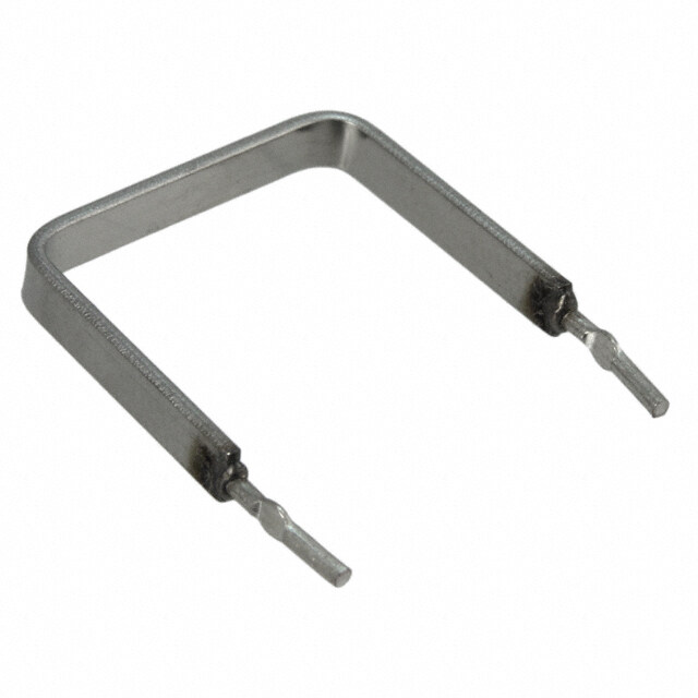
90 Series orDering inFormation Non-Inductive Winding RoHS Lead Free Vitreous Enamel Molded Optional (blank = std. winding) Compliant 91NJR10E Axial Term. Wirewound, 90 Series Wattage Tolerance Resistance Value 5% Tolerance Standard Series-Lead 1= 1.5W J=5% 1R0= 1.0Ω Free Vitreous 2= 2.25W 10R=10.0Ω Enamel Molded 3= 3.25W 250= 250Ω Axial Term. 5= 5W 1K0= 1,000Ω Wirewound 0=11W 4K5= 4,500Ω 51K=51,000Ω Standard part numbers for 90 series Wattage Wattage Wattage Wattage Wattage Ohmic value PPSaruerffftii xxN o. 91J ––– 1.5 92J –––2.25 93J –––3.25 95J ––– 5 90J ––– 11 Ohmic value PPSaruerffftii xxN o. 91J ––– 1.5 92J –––2.25 93J –––3.25 95J ––– 5 90J ––– 11 Ohmic value PPSaruerffftii xxN o. 91J ––– 1.5 92J –––2.25 93J –––3.25 95J ––– 5 90J ––– 11 Ohmic value PPSaruerffftii xxN o. 93J –––3.25 95J ––– 5 90J ––– 11 Ohmic value PPSaruerffftii xxN o. 95J ––– 5 90J ––– 11 1 –––1R0 22 –––22R 350 –––350 3,500 –––3K5 13,000 –––13K 1.1 –––1R1 24 –––24R 360 –––360 3,600 –––3K6 14,000 –––14K 1.2 –––1R2 25 –––25R 390 –––390 3,900 –––3K9 15,000 –––15K 1.3 –––1R3 27 –––27R 400 –––400 4,000 –––4K0 16,000 –––16K 1.5 –––1R5 30 –––30R 430 –––430 4,300 –––4K3 17,000 –––17K 1.6 –––1R6 33 –––33R 450 –––450 4,500 –––4K5 18,000 –––18K 1.8 –––1R8 35 –––35R 470 –––470 4,700 –––4K7 20,000 –––20K 2 –––2R0 36 –––36R 500 –––500 5,000 –––5K0 22,000 –––22K 2.2 –––2R2 39 –––39R 510 –––510 5,100 –––5K1 24,000 –––24K 2.4 –––2R4 40 –––40R 560 –––560 5,600 –––5K6 25,000 –––25K 2.7 –––2R7 43 –––43R 600 –––600 6,000 –––6K0 27,000 –––27K 3 –––3R0 47 –––47R 620 –––620 6,200 –––6K2 30,000 –––30K 3.3 –––3R3 50 –––50R 680 –––680 6,800 –––6K8 33,000 –––33K 3.6 –––3R6 51 –––51R 700 –––700 7,000 –––7K0 35,000 –––35K 3.9 –––3R9 56 –––56R 750 –––750 7,500 –––7K5 36,000 –––36K 4 –––4R0 62 –––62R 800 –––800 8,000 –––8K0 39,000 –––39K 4.3 –––4R3 68 –––68R 820 –––820 8,200 –––8K2 40,000 –––40K 4.7 –––4R7 75 –––75R 900 –––900 9,000 –––9K0 43,000 –––43K 5 –––5R0 82 –––82R 910 –––910 9,100 –––9K1 45,000 –––45K 5.1 –––5R1 91 –––91R 1,000 –––1K0 10,000 –––10K 47,000 –––47K 5.6 –––5R6 100 –––100 1,100 –––1K1 11,000 –––11K 50,000 –––50K 6.2 –––6R2 110 –––110 1,200 –––1K2 12,000 –––12K 51,000 –––51K 6.8 –––6R8 120 –––120 1,300 –––1K3 7.5 –––7R5 130 –––130 1,400 –––1K4 = Standard values 8.2 –––8R2 150 –––150 1,500 –––1K5 = Non-standard values subject to minimum handling 9.1 –––9R1 160 –––160 1,600 –––1K6 charge per item 10 –––10R 180 –––180 1,800 –––1K8 11 –––11R 200 –––200 2,000 –––2K0 Shaded values involve very fine resistance wire and 12 –––12R 220 –––220 2,200 –––2K2 should not be used in critical applications without burn- 13 –––13R 240 –––240 2,400 –––2K4 in and/or thermal cycling. 15 –––15R 250 –––250 2,500 –––2K5 16 –––16R 270 –––270 2,700 –––2K7 18 –––18R 300 –––300 3,000 –––3K0 20 –––20R 330 –––330 3,300 –––3K3 mounting Clip FeatureS • Prevents severe vibration or mechanical shock to resistor • Increases resistor wattage up to 100% when mounted on metal surface (1.5 sq. in. by 0.040 in. thick min. per watt dissipated) • Holes in clip base permit fastening to chassis surface with machine screws, eyelets or rivets • Sold in bags of ten (10) Standard part numbers for mounting clip Resistor Clip Clip Clip Hole Hole rating length width height No. of centers diameter Part No. (watts) (in./mm) (in./mm) (in./mm) holes (in./mm) (in./mm) = Most popular standard values 5900 1.5 0.40 / 10.319 0.150 / 3.810 0.250 / 6.350 1 0.71 / 1.803 = Standard values 5902 2.25 0.35 / 8.890 0.217 / 5.500 0.275 / 6.980 2 0.156 / 3.969 0.71 / 1.803 = Non-standard values subject to 5904 3.25 0.50 / 12.700 0.257 / 6.500 0.319 / 8.103 2 0.250 / 6.350 0.093 / 2.362 minimum handling charge per 5906 5.0 0.90 / 22.860 0.237 / 6.019 0.284 / 7.214 2 0.400 / 10.160 0.103 / 2.616 item 5908 11.0 1.75 / 44.450 0.333 / 8.458 0.377 / 9.576 2 0.800 / 20.320 0.103 / 2.616 90 1-866-9-OHMITE • Int’l 1-847-258-0300 • Fax 1-847-574-7522 • www.ohmite.com • info@ohmite.com
Mouser Electronics Authorized Distributor Click to View Pricing, Inventory, Delivery & Lifecycle Information: O hmite: 95J9K0 95J5R6 95J5R0 95J3R3 91J7R5 90J7R5 91J700 91J18R 91J10R 92J30R 93J50R 92J5R6 93J25R 92J5R0 92J560 93J27R 92J5R1 95J2K0 93J450 91J43R 92J68R 92J62R 91J40R 91J47R 92J500 95J40R 90J820 90J800 95J47R 95J43R 90J8K0 90J8K2 95J680 95J82R 95J600 92J8R2 92J800 92J820 95J820 95J8R2 90J82R 91J62R 91J400 91J68R 91J75R 91J510 95J1R0 95J1R2 91J3R0 90J3R3 91J300 91J3R9 91J3R3 91J3R6 91J1K0 91J350 91J330 91J390 91J360 91J3K0 93J2R4 93J2R0 93J2R2 93J220 93J2R7 93J240 93J200 95J120 90J16K 95J30R 90J18R 95J35R 90J18K 95J1R6 90J10R 90J10K 90J14K 95J1R8 90J13K 90J11K 95J1R3 90J17K 90J15R 90J11R 95J39R 95J33R 90J15K 90J13R 95J160 95J130 95J150 95J1K5 90J700 90J330 95J1K6 95J110 90J3K9 90J750 90J3K3 95J1R5