ICGOO在线商城 > 集成电路(IC) > 逻辑 - 多频振荡器 > 74VHC123ASJX

 Datasheet下载
- 型号: 74VHC123ASJX
- 制造商: Fairchild Semiconductor
- 库位|库存: xxxx|xxxx
- 要求:
| 数量阶梯 | 香港交货 | 国内含税 |
| +xxxx | $xxxx | ¥xxxx |
查看当月历史价格
查看今年历史价格
74VHC123ASJX产品简介:
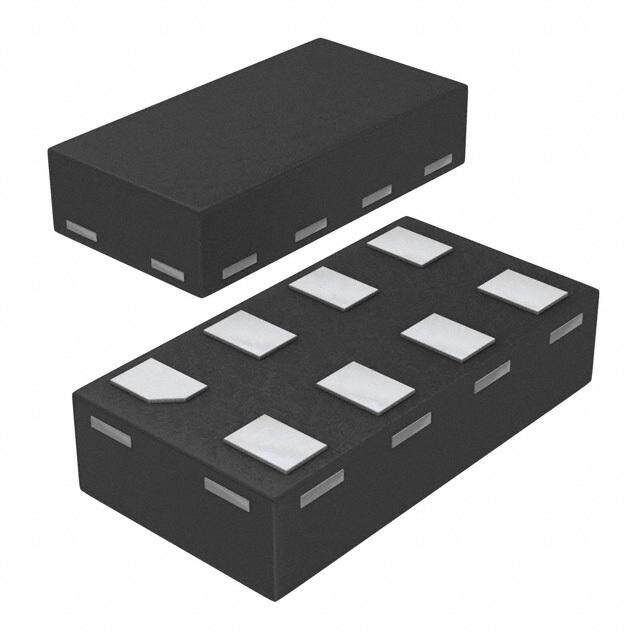
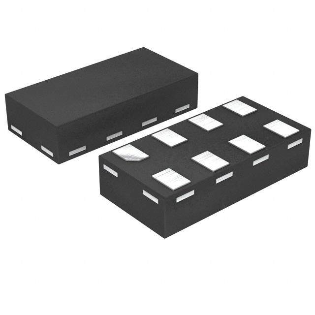
ICGOO电子元器件商城为您提供74VHC123ASJX由Fairchild Semiconductor设计生产,在icgoo商城现货销售,并且可以通过原厂、代理商等渠道进行代购。 74VHC123ASJX价格参考¥1.31-¥6.82。Fairchild Semiconductor74VHC123ASJX封装/规格:逻辑 - 多频振荡器, Monostable Multivibrator 8.1ns 16-SOP。您可以下载74VHC123ASJX参考资料、Datasheet数据手册功能说明书,资料中有74VHC123ASJX 详细功能的应用电路图电压和使用方法及教程。
| 参数 | 数值 |
| 产品目录 | 集成电路 (IC)半导体 |
| 描述 | MULTIVIBRATOR DUAL MONO 16SOP单稳态多谐振荡器 Dual Multivibrator |
| 产品分类 | |
| 品牌 | Fairchild Semiconductor |
| 产品手册 | |
| 产品图片 |
|
| rohs | 符合RoHS无铅 / 符合限制有害物质指令(RoHS)规范要求 |
| 产品系列 | 逻辑集成电路,单稳态多谐振荡器,Fairchild Semiconductor 74VHC123ASJX74VHC |
| 数据手册 | |
| 产品型号 | 74VHC123ASJX |
| 产品种类 | 单稳态多谐振荡器 |
| 传播延迟 | 8.1ns |
| 传播延迟时间 | 24.1 ns, 14 ns |
| 低电平输出电流 | 8 mA |
| 供应商器件封装 | 16-SOP |
| 其它名称 | 74VHC123ASJXCT |
| 包装 | 剪切带 (CT) |
| 单位重量 | 242 mg |
| 商标 | Fairchild Semiconductor |
| 安装类型 | 表面贴装 |
| 安装风格 | SMD/SMT |
| 封装 | Reel |
| 封装/外壳 | 16-SOIC(0.209",5.30mm 宽) |
| 封装/箱体 | SOP-16 |
| 工作温度 | -40°C ~ 85°C |
| 工作电源电压 | 2.5 V, 3.3 V, 5 V |
| 工厂包装数量 | 2000 |
| 施密特触发器输入 | 无 |
| 最大功率耗散 | 73 pF |
| 最大工作温度 | + 85 C |
| 最小工作温度 | - 40 C |
| 标准包装 | 1 |
| 每芯片元件 | 2 |
| 独立电路 | 2 |
| 电压-电源 | 2 V ~ 5.5 V |
| 电流-输出高,低 | 8mA,8mA |
| 电源电压-最大 | 5.5 V |
| 电源电压-最小 | 2 V |
| 系列 | 74VHC123A |
| 逻辑类型 | 单稳态 |
| 逻辑系列 | VHC |
| 零件号别名 | 74VHC123ASJX_NL |
| 高电平输出电流 | - 8 mA |


- 商务部:美国ITC正式对集成电路等产品启动337调查
- 曝三星4nm工艺存在良率问题 高通将骁龙8 Gen1或转产台积电
- 太阳诱电将投资9.5亿元在常州建新厂生产MLCC 预计2023年完工
- 英特尔发布欧洲新工厂建设计划 深化IDM 2.0 战略
- 台积电先进制程称霸业界 有大客户加持明年业绩稳了
- 达到5530亿美元!SIA预计今年全球半导体销售额将创下新高
- 英特尔拟将自动驾驶子公司Mobileye上市 估值或超500亿美元
- 三星加码芯片和SET,合并消费电子和移动部门,撤换高东真等 CEO
- 三星电子宣布重大人事变动 还合并消费电子和移动部门
- 海关总署:前11个月进口集成电路产品价值2.52万亿元 增长14.8%


PDF Datasheet 数据手册内容提取
Is Now Part of To learn more about ON Semiconductor, please visit our website at www.onsemi.com Please note: As part of the Fairchild Semiconductor integration, some of the Fairchild orderable part numbers will need to change in order to meet ON Semiconductor’s system requirements. Since the ON Semiconductor product management systems do not have the ability to manage part nomenclature that utilizes an underscore (_), the underscore (_) in the Fairchild part numbers will be changed to a dash (-). This document may contain device numbers with an underscore (_). Please check the ON Semiconductor website to verify the updated device numbers. The most current and up-to-date ordering information can be found at www.onsemi.com. Please email any questions regarding the system integration to Fairchild_questions@onsemi.com. ON Semiconductor and the ON Semiconductor logo are trademarks of Semiconductor Components Industries, LLC dba ON Semiconductor or its subsidiaries in the United States and/or other countries. ON Semiconductor owns the rights to a number of patents, trademarks, copyrights, trade secrets, and other intellectual property. A listing of ON Semiconductor’s product/patent coverage may be accessed at www.onsemi.com/site/pdf/Patent-Marking.pdf. ON Semiconductor reserves the right to make changes without further notice to any products herein. ON Semiconductor makes no warranty, representation or guarantee regarding the suitability of its products for any particular purpose, nor does ON Semiconductor assume any liability arising out of the application or use of any product or circuit, and specifically disclaims any and all liability, including without limitation special, consequential or incidental damages. Buyer is responsible for its products and applications using ON Semiconductor products, including compliance with all laws, regulations and safety requirements or standards, regardless of any support or applications information provided by ON Semiconductor. “Typical” parameters which may be provided in ON Semiconductor data sheets and/or specifications can and do vary in different applications and actual performance may vary over time. All operating parameters, including “Typicals” must be validated for each customer application by customer’s technical experts. ON Semiconductor does not convey any license under its patent rights nor the rights of others. ON Semiconductor products are not designed, intended, or authorized for use as a critical component in life support systems or any FDA Class 3 medical devices or medical devices with a same or similar classification in a foreign jurisdiction or any devices intended for implantation in the human body. Should Buyer purchase or use ON Semiconductor products for any such unintended or unauthorized application, Buyer shall indemnify and hold ON Semiconductor and its officers, employees, subsidiaries, affiliates, and distributors harmless against all claims, costs, damages, and expenses, and reasonable attorney fees arising out of, directly or indirectly, any claim of personal injury or death associated with such unintended or unauthorized use, even if such claim alleges that ON Semiconductor was negligent regarding the design or manufacture of the part. ON Semiconductor is an Equal Opportunity/Affirmative Action Employer. This literature is subject to all applicable copyright laws and is not for resale in any manner.
7 4 V H C May 2007 1 2 74VHC123A 3 A tm Dual Retriggerable Monostable Multivibrator D u a l Features General Description R e t ■ High Speed: t = 8.1ns (Typ.) at T = 25°C The VHC123A is an advanced high speed CMOS r PD A i g ■ Low Power Dissipation: ICC = 4µA (Max) at TA = 25°C Monostable Multivibrator fabricated with silicon gate g ■ Active State: ICC = 600µA (Max.) at TA = 25°C CMOS technology. It achieves the high speed operation er similar to equivalent Bipolar Schottky TTL while main- a ■ High Noise Immunity: V = V = 28% V (Min.) b NIH NIL CC taining the CMOS low power dissipation. Each multi- l ■ Power down protection is provided on all inputs vibrator features both a negative, A, and a positive, B, e M ■ Pin and function compatible with 74HC123A transition triggered input, either of which can be used as o an inhibit input. Also included is a clear input that when n o taken low resets the one-shot. The VHC123A can be s triggered on the positive transition of the clear while A is t a held low and B is held high. The output pulse width is b determined by the equation: PW = (R )(C ); where PW le x x is in seconds, R is in ohms, and C is in farads. M u Limits for Rx and Cx are: lti v External capacitor, C : No limit i x b External resistors, R : V = 2.0V, 5 kΩ min ra x VCC > 3.0V, 1 kΩ min to CC r An input protection circuit ensures that 0 to 7V can be applied to the input pins without regard to the supply voltage. This device can be used to interface 5V to 3V systems and two supply systems such as battery back up. This circuit prevents device destruction due to mis- matched supply and input voltages. Ordering Information Package Order Number Number Package Description 74VHC123AM M16A 16-Lead Small Outline Integrated Circuit (SOIC), JEDEC MS-012, 0.150” Narrow 74VHC123ASJ M16D 16-Lead Small Outline Package (SOP), EIAJ TYPE II, 5.3mm Wide 74VHC123AMTC MTC16 16-Lead Thin Shrink Small Outline Package (TSSOP), JEDEC MO-153, 4.4mm Wide Surface mount packages are also available on Tape and Reel. Specify by appending the suffix letter “X” to the ordering number. ©1993 Fairchild Semiconductor Corporation www.fairchildsemi.com 74VHC123A Rev. 1.2
7 4 Connection Diagram Logic Symbol V H C IEEE/IEC 1 2 3 A D u a l R e t r i g g e r a b l e M o n o s t a b l e Pin Description M u Pin Names Description Truth Table lt i A Trigger Inputs (Negative Edge) v i Inputs Outputs b B Trigger Inputs (Positive Edge) r a A B CLR Q Q Function t CLR Reset Inputs o H H Output Enable r C External Capacitor x X L H L H Inhibit R External Resistor x H X H L H Inhibit Q, Q Outputs L H Output Enable L H Output Enable X X L L H Reset H = HIGH Voltage Level L = LOW Voltage Level = HIGH-to-LOW Transition = LOW-to-HIGH Transition X = Don't Care ©1993 Fairchild Semiconductor Corporation www.fairchildsemi.com 74VHC123A Rev. 1.2 2
7 4 Block Diagrams V H C 1 2 3 A D u a l R e t r i g g e r a b l e M o n o s t a Note A: Cx, Rx, Dx are external Capacitor, Resistor, and Diode, respectively. b l e Note B: External clamping diode, Dx; M External capacitor is charged to V level in the wait state, i.e. when no trigger is applied. u CC l t If the supply voltage is turned off, Cx discharges mainly through the internal (parasitic) diode. If Cx is sufficiently large iv and VCC drops rapidly, there will be some possibility of damaging the IC through in rush current or latch-up. If the ib capacitance of the supply voltage filter is large enough and VCC drops slowly, the in rush current is automatically ra limited and damage to the IC is avoided. to r The maximum value of forward current through the parasitic diode is ±20mA. In the case of a large Cx, the limit of fall time of the supply voltage is determined as follows: t ≥ (V –0.7) C / 20mA f CC x (t is the time between the supply voltage turn off and the supply voltage reaching 0.4 V ) f CC In the event a system does not satisfy the above condition, an external clamping diode (D ) is needed to protect the IC x from rush current. ©1993 Fairchild Semiconductor Corporation www.fairchildsemi.com 74VHC123A Rev. 1.2 3
7 4 System Diagram V H C 1 2 3 A D u a l R e t r i g g e r a b l e M o n o s t a b l e M u l t i v i b r a t o r Timing Chart ©1993 Fairchild Semiconductor Corporation www.fairchildsemi.com 74VHC123A Rev. 1.2 4
7 4 Functional Description V H C 1. Stand-by State the output Q goes LOW and C stops its operation. 2 1 The external capacitor (C ) is fully charged to V in That means, after triggering, when the voltage level 2 x CC 3 the Stand-by State. That means, before triggering, of the Rx/Cx node reaches VrefH, the IC returns to its A the QP and QN transistors which are connected to the MONOSTABLE state. D Rx/Cx node are in the off state. Two comparators that With large values of Cx and Rx, and ignoring the dis- u relate to the timing of the output pulse, and two refer- charge time of the capacitor and internal delays of al ence voltage supplies turn off. The total supply cur- the IC, the width of the output pulse, t (OUT), is as R W rent is only leakage current. follows: et r 2. Trigger Operation t (OUT) = 1.0 C R ig W x x g Trigger operation is effective in any of the following 3. Retrigger operation (74VHC123A) e three cases. First, the condition where the A input is ra LOW, and B input has a rising signal; second, where When a new trigger is applied to either input A or B b the B input is HIGH, and the A input has a falling sig- while in the MONOSTABLE state, it is effective only if le the IC is charging C . The voltage level of the R /C M nal; and third, where the A input is LOW and the B x x x node then falls to V L level again. Therefore the Q o input is HIGH, and the CLR input has a rising signal. ref n output stays HIGH if the next trigger comes in before o After a trigger becomes effective, comparators C1 the time period set by Cx and Rx. st and C2 start operating, and QN is turned on. The a If the new trigger is very close to a previous trigger, b external capacitor discharges through Q . The volt- N l such as an occurrence during the discharge cycle, it e age level at the Rx/Cx node drops. If the Rx/Cx volt- will have no effect. M age level falls to the internal reference voltage V L, ref u the output of C1 becomes LOW. The flip-flop is then The minimum time for a trigger to be effective 2nd lt reset and QN turns off. At that moment C1 stops but trigger, tRR (Min), depends on VCC and Cx. ivi C continues operating. b 2 4. Reset Operation r a After QN turns off, the voltage at the Rx/Cx node In normal operation, the CLR input is held HIGH. If to starts rising at a rate determined by the time constant CLR is LOW, a trigger has no affect because the Q r of external capacitor C and resistor R . x x output is held LOW and the trigger control F/F is Upon triggering, output Q becomes HIGH, following reset. Also, Qp turns on and Cx is charged rapidly to some delay time of the internal F/F and gates. It stays VCC. HIGH even if the voltage of R /C changes from fall- x x This means if CLR is set LOW, the IC goes into a wait ing to rising. When R /C reaches the internal refer- x x state. ence voltage V H, the output of C becomes LOW, ref 2 ©1993 Fairchild Semiconductor Corporation www.fairchildsemi.com 74VHC123A Rev. 1.2 5
7 4 Absolute Maximum Ratings V H Stresses exceeding the absolute maximum ratings may damage the device. The device may not function or be C operable above the recommended operating conditions and stressing the parts to these levels is not recommended. 1 2 In addition, extended exposure to stresses above the recommended operating conditions may affect device reliability. 3 A The absolute maximum ratings are stress ratings only. D Symbol Parameter Rating u a V Supply Voltage –0.5V to +7.0V l CC R V DC Input Voltage –0.5V to +7.0V e IN t r V DC Output Voltage –0.5V to V + 0.5V i OUT CC g g I Input Diode Current –20mA IK e r I Output Diode Current ±20mA a OK b IOUT DC Output Current ±25mA le I DC V /GND Current ±50mA M CC CC o T Storage Temperature –65°C to +150°C n STG o T Lead Temperature (Soldering, 10 seconds) 260°C s L t a b l e Recommended Operating Conditions(1) M u The Recommended Operating Conditions table defines the conditions for actual device operation. Recommended l t operating conditions are specified to ensure optimal performance to the datasheet specifications. Fairchild does not iv recommend exceeding them or designing to absolute maximum ratings. ib r a Symbol Parameter Rating t o r V Supply Voltage 2.0V to +5.5V CC V Input Voltage 0V to +5.5V IN V Output Voltage 0V to V OUT CC T Operating Temperature –40°C to +85°C OPR t , t Input Rise and Fall Time (CLR only) r f V = 3.3V ± 0.3V 0ns/V ∼ 100ns/V CC V = 5.0V ± 0.5V 0ns/V ∼ 20ns/V CC External Capacitor, C No Limitation(2) F x External Resistor, R >5kΩ(2) (V = 2.0V) x CC >1kΩ(2) (V > 3.0V) CC Notes: 1. Unused inputs must be held HIGH or LOW. They may not float. 2. The maximum allowable values of C and R are a function of the leakage of capacitor C , the leakage of the device, x x x and leakage due to board layout and surface resistance. Susceptibility to externally induced noise signals may occur for R > 1MΩ. x ©1993 Fairchild Semiconductor Corporation www.fairchildsemi.com 74VHC123A Rev. 1.2 6
7 4 DC Electrical Characteristics V H C TA = 25°C TA = –40° to 85°C 1 2 Symbol Parameter VCC (V) Conditions Min. Typ. Max. Min. Max. Units 3 A VIH HIGH Level Input 2.0 1.50 1.50 V Voltage D 3.0–5.5 0.7 x VCC 0.7 x VCC u a VIL LOW Level Input 2.0 0.50 0.50 V l Voltage R 3.0–5.5 0.3 x V 0.3 x V CC CC e VOH HIGH Level Output 2.0 VIN = VIH IOH = –50µA 1.9 2.0 1.9 V tri Voltage or V g 3.0 IL 2.9 3.0 2.9 g e 4.5 4.4 4.5 4.4 r a 3.0 I = –4mA 2.58 2.48 b OH l 4.5 IOH = –8mA 3.94 3.80 e M VOL LOW Level Output 2.0 VIN = VIH IOL = 50µA 0.0 0.1 0.1 V o Voltage or V n 3.0 IL 0.0 0.1 0.1 o s 4.5 0.0 0.1 0.1 t a 3.0 I = 4mA 0.36 0.44 b OL l 4.5 IOL = 8mA 0.36 0.44 e M IIN Input Leakage 0–5.5 VIN = 5.5V or GND ±0.1 ±1.0 µA u Current lt i IIN Rx/Cx Terminal 5.5 VIN = VCC or GND ±0.25 ±2.50 µA vib Off-State Current r a ICC Quiescent Supply 5.5 VIN = VCC or GND 4.0 40.0 µA to Current r I Active—State(3) 3.0 V = V or GND, 160 250 280 µA CC IN CC Supply Current 4.5 Rx/Cx = 0.5 VCC 380 500 650 5.5 560 750 975 Note: 3. Per circuit. ©1993 Fairchild Semiconductor Corporation www.fairchildsemi.com 74VHC123A Rev. 1.2 7
7 4 AC Electrical Characteristics(4) V H C TA = –40°C 1 T = 25°C to +85°C 2 A 3 A Symbol Parameter V (V) Conditions Min. Typ. Max. Min. Max. Units CC t , t Propagation Delay Time 3.3 ± 0.3 C = 15 pF 13.4 20.6 1.0 24.0 ns D PLH PHL L u (A, B–Q, Q) C = 50 pF 15.9 24.1 1.0 27.5 a L l 5.0 ± 0.5 C = 15 pF 8.1 12.0 1.0 14.0 ns R L e CL = 50 pF 9.6 14.0 1.0 16.0 tri g tPLH, tPHL Propagation Delay Time 3.3 ± 0.3 CL = 15 pF 14.5 22.4 1.0 26.0 ns g (CLR Trigger—Q, Q) CL = 50 pF 17.0 25.9 1.0 29.5 era 5.0 ± 0.5 C = 15 pF 8.7 12.9 1.0 15.0 ns b L l e CL = 50 pF 10.2 14.9 1.0 17.0 M t , t Propagation Delay Time 3.3 ± 0.3 C = 15 pF 10.3 15.8 1.0 18.5 ns o PLH PHL L n (CLR—Q, Q) C = 50 pF 12.8 19.3 1.0 22.0 o L s 5.0 ± 0.5 C = 15 pF 6.3 9.4 1.0 11.0 ns t L a CL = 50 pF 7.8 11.4 1.0 13.0 ble tWOUT Output Pulse Width 3.3 ± 0.3 CL = 50pF, Cx = 28pF, 160 240 300 ns M 5.0 ± 0.5 Rx = 2kΩ 133 200 240 ul t 3.3 ± 0.3 C = 50pF, C = 0.01µF, 90 100 110 90 110 µs iv L x i 5.0 ± 0.5 Rx = 10kΩ 90 100 110 90 110 br a 3.3 ± 0.3 C = 50pF, C = 0.1µF, 0.9 1.0 1.1 0.9 1.1 ms t L x o 5.0 ± 0.5 Rx = 1kΩ 0.9 1.0 1.1 0.9 1.1 r ∆t Output Pulse Width Error ±1 % WOUT Between Circuits (In same Package) C Input Capacitance V = Open 4 10 10 pF IN CC C Power Dissipation (5) 73 pF PD Capacitance Notes: 4. Refer to Timing Chart. 5. C is defined as the value of the internal equivalent capacitance which is calculated from the operating current PD consumption without load. Average operating current can be obtained by the equation: I (opr.) = C • V • f I 1 • Duty / 100 + I / 2 (per Circuit) CC PD CC IN+ CC CC I 1: Active Supply Current CC Duty: % ©1993 Fairchild Semiconductor Corporation www.fairchildsemi.com 74VHC123A Rev. 1.2 8
7 4 AC Operating Requirement(6) V H C TA = –40°C 1 T = 25°C to +85°C 2 A 3 A Symbol Parameter V (V) Conditions Min. Typ. Max. Min. Max. Units CC D tW(L), tW(H) Minimum Trigger 3.3 5.0 5.0 ns u a Pulse Width 5.0 5.0 5.0 l R tW(L) Minimum Clear 3.3 5.0 5.0 ns e Pulse Width 5.0 5.0 5.0 tri g t Minimum Retrigger 3.3 ± 0.3 R = 1kΩ, 60 ns g RR x e Time 5.0 ± 0.5 CX = 100pF 39 ra b 3.3 Rx = 1kΩ, 1.5 µs le C = 0.01µF 5.0 X 1.2 M o Note: n o 6. Refer to Timing Chart. s t a b l e M u l t i v i b r a t o r ©1993 Fairchild Semiconductor Corporation www.fairchildsemi.com 74VHC123A Rev. 1.2 9
7 4 Device Characteristics V H C t *C Characteristics (Typ.) t *V Characteristics (Typ.) wout x RR CC 1 2 3 A D u a l R e t r i g g e r a b l e M o n o s t a b l e M u l t Output Pulse Width Constant K-Supply Voltage Input Equivalent Circuit iv i (Typ.) b r a t o r ©1993 Fairchild Semiconductor Corporation www.fairchildsemi.com 74VHC123A Rev. 1.2 10
7 4 Physical Dimensions V H Dimensions are in millimeters unless otherwise noted. C 1 2 3 A D u a l R e t r i g g e r a b l e M o n o s t a b l e M u l t i v i b r a t o r Figure 1. 16-Lead Small Outline Integrated Circuit (SOIC), JEDEC MS-012, 0.150" Narrow Package Number M16A ©1993 Fairchild Semiconductor Corporation www.fairchildsemi.com 74VHC123A Rev. 1.2 11
7 4 Physical Dimensions (Continued) V H Dimensions are in millimeters unless otherwise noted. C 1 2 3 A D u a l R e t r i g g e r a b l e M o n o s t a b l e M u l t i v i b r a t o r Figure 2. 16-Lead Small Outline Package (SOP), EIAJ TYPE II, 5.3mm Wide Package Number M16D ©1993 Fairchild Semiconductor Corporation www.fairchildsemi.com 74VHC123A Rev. 1.2 12
7 4 Physical Dimensions (Continued) V H Dimensions are in millimeters unless otherwise noted. C 1 2 3 A D u 5.00±0.10 a l 4.55 R e t r i 5.90 g g e r 4.45 7.35 a b l e 0.65 M 4.4±0.1 o n o 1.45 s t a b l e M 5.00 u l t i v 0.11 ib r a t o r 12° MTC16rev4 Figure 3. 16-Lead Thin Shrink Small Outline Package (TSSOP), JEDEC MO-153, 4.4mm Wide Package Number MTC16 ©1993 Fairchild Semiconductor Corporation www.fairchildsemi.com 74VHC123A Rev. 1.2 13
7 4 V H C 1 2 3 TRADEMARKS A ThefollowingareregisteredandunregisteredtrademarksFairchildSemiconductorownsorisauthorizedtouseandisnotintendedtobean D exhaustivelistofallsuchtrademarks. u ACEx® i-Lo™ Power-SPM™ TinyBoost™ al Acrosstheboard.Aroundtheworld.™ ImpliedDisconnect™ PowerTrench® TinyBuck™ R ActiveArray™ IntelliMAX™ ProgrammableActiveDroop™ TinyLogic® e Bottomless™ ISOPLANAR™ QFET® TINYOPTO™ tr i BuilditNow™ MICROCOUPLER™ QS™ TinyPower™ g g CoolFET™ MicroPak™ QTOptoelectronics™ TinyWire™ e CROSSVOLT™ MICROWIRE™ QuietSeries™ TruTranslation™ r a CTL™ Motion-SPM™ RapidConfigure™ µSerDes™ b CurrentTransferLogic™ MSX™ RapidConnect™ UHC® le DOME™ MSXPro™ ScalarPump™ UniFET™ M E2CMOS™ OCX™ SMARTSTART™ VCX™ o EcoSPARK® OCXPro™ SPM® Wire™ n EnSigna™ OPTOLOGIC® STEALTH™ o FACTQuietSeries™ OPTOPLANAR® SuperFET™ st FFAACSTT®® PPDACP-MSAPNM™™ SSuuppeerrSSOOTT™™--36 abl e FASTr™ POP™ SuperSOT™-8 M FPS™ Power220® SyncFET™ FRFET® Power247® TCM™ ul GlobalOptoisolator™ PowerEdge™ ThePowerFranchise® ti v GTO™ PowerSaver™ ™ i b HiSeC™ r a t o DISCLAIMER r FAIRCHILDSEMICONDUCTORRESERVESTHERIGHTTOMAKECHANGESWITHOUTFURTHERNOTICETOANYPRODUCTS HEREINTOIMPROVERELIABILITY,FUNCTIONORDESIGN.FAIRCHILDDOESNOTASSUMEANYLIABILITYARISINGOUTOFTHE APPLICATIONORUSEOFANYPRODUCTORCIRCUITDESCRIBEDHEREIN;NEITHERDOESITCONVEYANYLICENSEUNDER ITSPATENTRIGHTS,NORTHERIGHTSOFOTHERS.THESESPECIFICATIONSDONOTEXPANDTHETERMSOFFAIRCHILD’S WORLDWIDETERMSANDCONDITIONS,SPECIFICALLYTHEWARRANTYTHEREIN,WHICHCOVERSTHESEPRODUCTS. LIFESUPPORTPOLICY FAIRCHILD’SPRODUCTSARENOTAUTHORIZEDFORUSEASCRITICALCOMPONENTSINLIFESUPPORTDEVICESOR SYSTEMSWITHOUTTHEEXPRESSWRITTENAPPROVALOFFAIRCHILDSEMICONDUCTORCORPORATION. Asusedherein: 1. Life support devices or systems are devices or systems 2. A critical component in any component of a life support, which, (a) are intended for surgical implant into the bodyor device, or system whose failure to perform can be (b) support or sustain life, and (c) whose failure to perform reasonablyexpectedtocausethefailureofthelifesupport when properly used in accordance with instructions for use deviceorsystem,ortoaffectitssafetyoreffectiveness. provided in the labeling, can be reasonably expected to resultinasignificantinjuryoftheuser. PRODUCTSTATUSDEFINITIONS DefinitionofTerms DatasheetIdentification ProductStatus Definition AdvanceInformation FormativeorInDesign Thisdatasheetcontainsthedesignspecificationsforproduct development.Specificationsmaychangeinanymannerwithoutnotice. Preliminary FirstProduction Thisdatasheetcontainspreliminarydata;supplementarydatawillbe publishedatalaterdate.FairchildSemiconductorreservestherightto makechangesatanytimewithoutnoticetoimprovedesign. NoIdentificationNeeded FullProduction Thisdatasheetcontainsfinalspecifications.FairchildSemiconductor reservestherighttomakechangesatanytimewithoutnoticetoimprove design. Obsolete NotInProduction Thisdatasheetcontainsspecificationsonaproductthathasbeen discontinuedbyFairchildSemiconductor.Thedatasheetisprintedfor referenceinformationonly. Rev.I26 ©1993 Fairchild Semiconductor Corporation www.fairchildsemi.com 74VHC123A Rev. 1.2 14
ON Semiconductor and are trademarks of Semiconductor Components Industries, LLC dba ON Semiconductor or its subsidiaries in the United States and/or other countries. ON Semiconductor owns the rights to a number of patents, trademarks, copyrights, trade secrets, and other intellectual property. A listing of ON Semiconductor’s product/patent coverage may be accessed at www.onsemi.com/site/pdf/Patent−Marking.pdf. ON Semiconductor reserves the right to make changes without further notice to any products herein. ON Semiconductor makes no warranty, representation or guarantee regarding the suitability of its products for any particular purpose, nor does ON Semiconductor assume any liability arising out of the application or use of any product or circuit, and specifically disclaims any and all liability, including without limitation special, consequential or incidental damages. Buyer is responsible for its products and applications using ON Semiconductor products, including compliance with all laws, regulations and safety requirements or standards, regardless of any support or applications information provided by ON Semiconductor. “Typical” parameters which may be provided in ON Semiconductor data sheets and/or specifications can and do vary in different applications and actual performance may vary over time. All operating parameters, including “Typicals” must be validated for each customer application by customer’s technical experts. ON Semiconductor does not convey any license under its patent rights nor the rights of others. ON Semiconductor products are not designed, intended, or authorized for use as a critical component in life support systems or any FDA Class 3 medical devices or medical devices with a same or similar classification in a foreign jurisdiction or any devices intended for implantation in the human body. Should Buyer purchase or use ON Semiconductor products for any such unintended or unauthorized application, Buyer shall indemnify and hold ON Semiconductor and its officers, employees, subsidiaries, affiliates, and distributors harmless against all claims, costs, damages, and expenses, and reasonable attorney fees arising out of, directly or indirectly, any claim of personal injury or death associated with such unintended or unauthorized use, even if such claim alleges that ON Semiconductor was negligent regarding the design or manufacture of the part. ON Semiconductor is an Equal Opportunity/Affirmative Action Employer. This literature is subject to all applicable copyright laws and is not for resale in any manner. PUBLICATION ORDERING INFORMATION LITERATURE FULFILLMENT: N. American Technical Support: 800−282−9855 Toll Free ON Semiconductor Website: www.onsemi.com Literature Distribution Center for ON Semiconductor USA/Canada 19521 E. 32nd Pkwy, Aurora, Colorado 80011 USA Europe, Middle East and Africa Technical Support: Order Literature: http://www.onsemi.com/orderlit Phone: 303−675−2175 or 800−344−3860 Toll Free USA/Canada Phone: 421 33 790 2910 Fax: 303−675−2176 or 800−344−3867 Toll Free USA/Canada Japan Customer Focus Center For additional information, please contact your local Email: orderlit@onsemi.com Phone: 81−3−5817−1050 Sales Representative © Semiconductor Components Industries, LLC www.onsemi.com www.onsemi.com 1
Mouser Electronics Authorized Distributor Click to View Pricing, Inventory, Delivery & Lifecycle Information: O N Semiconductor: 74VHC123AMTC 74VHC123ASJX 74VHC123AM 74VHC123AMTCX 74VHC123ASJ 74VHC123AMX