ICGOO在线商城 > 集成电路(IC) > 逻辑 - 信号开关,多路复用器,解码器 > 74HC251D,653
- 型号: 74HC251D,653
- 制造商: NXP Semiconductors
- 库位|库存: xxxx|xxxx
- 要求:
| 数量阶梯 | 香港交货 | 国内含税 |
| +xxxx | $xxxx | ¥xxxx |
查看当月历史价格
查看今年历史价格
74HC251D,653产品简介:
ICGOO电子元器件商城为您提供74HC251D,653由NXP Semiconductors设计生产,在icgoo商城现货销售,并且可以通过原厂、代理商等渠道进行代购。 74HC251D,653价格参考¥1.85-¥3.12。NXP Semiconductors74HC251D,653封装/规格:逻辑 - 信号开关,多路复用器,解码器, Multiplexer 1 x 8:1 16-SO。您可以下载74HC251D,653参考资料、Datasheet数据手册功能说明书,资料中有74HC251D,653 详细功能的应用电路图电压和使用方法及教程。
Nexperia USA Inc.生产的74HC251D,653是一款逻辑信号开关,属于多路复用器(MUX)系列。该器件的主要功能是将多个输入信号选择性地传输到一个输出通道上,广泛应用于各种电子设备中,特别是在需要对多个数据源进行选择和切换的场景中。

 应用场景

1. 微处理器系统:
   在微处理器系统中,74HC251D,653可以用于选择不同的数据总线或地址总线,以便将来自不同外设的数据传输到CPU或内存。它可以帮助简化电路设计,减少所需的控制线数量。

2. 通信设备:
   在通信设备中,多路复用器用于在多个信道之间切换信号。例如,在电话交换机或网络路由器中,74HC251D,653可以用于选择不同的通信路径,确保数据包能够正确路由到目标地址。

3. 测试与测量仪器:
   测试与测量仪器如示波器、频谱分析仪等,通常需要处理来自多个传感器或信号源的数据。74HC251D,653可以用于选择不同的输入通道,以便在显示屏上显示特定的信号波形或频谱。

4. 音频/视频切换:
   在家庭影院系统或多媒体设备中,74HC251D,653可以用于切换不同的音频或视频源。例如,用户可以通过遥控器选择不同的输入设备(如蓝光播放器、游戏机或电视盒),而多路复用器则负责将选定的信号传递给显示器或扬声器。

5. 工业自动化:
   在工业控制系统中,多路复用器可以用于选择不同的传感器或执行器信号。例如,在PLC(可编程逻辑控制器)中,74HC251D,653可以用于选择不同的输入信号(如温度、压力、流量等),并将这些信号传递给中央处理单元进行处理和控制。

6. 汽车电子:
   在现代汽车中,74HC251D,653可以用于切换不同的车载传感器信号,如车速传感器、温度传感器、刹车传感器等。此外,它还可以用于切换不同的娱乐系统输入源,如收音机、CD播放器或USB接口。

 总结

74HC251D,653作为一种高性能的多路复用器,具有低功耗、高可靠性和广泛的兼容性,适用于多种应用场景。它不仅能够简化电路设计,还能提高系统的灵活性和响应速度,特别适合于需要频繁切换多个输入信号的应用场合。
| 参数 | 数值 |
| 产品目录 | 集成电路 (IC)半导体 |
| 描述 | IC 8-INPUT MUX 3-ST 16SOIC编码器、解码器、复用器和解复用器 8-INPUT MUX 3-STATE |
| 产品分类 | |
| 品牌 | NXP Semiconductors |
| 产品手册 | |
| 产品图片 |
|
| rohs | 符合RoHS无铅 / 符合限制有害物质指令(RoHS)规范要求 |
| 产品系列 | 逻辑集成电路,编码器、解码器、复用器和解复用器,NXP Semiconductors 74HC251D,65374HC |
| 数据手册 | |
| 产品型号 | 74HC251D,653 |
| PCN封装 | |
| PCN组件/产地 | |
| 产品 | Decoders, Encoders, Multiplexers & Demultiplexers |
| 产品培训模块 | http://www.digikey.cn/PTM/IndividualPTM.page?site=cn&lang=zhs&ptm=24983 |
| 产品种类 | 编码器、解码器、复用器和解复用器 |
| 传播延迟时间 | 175 ns at 2 V, 35 ns at 4.5 V, 30 ns at 6 V |
| 供应商器件封装 | 16-SO |
| 其它名称 | 568-8140-6 |
| 包装 | Digi-Reel® |
| 商标 | NXP Semiconductors |
| 安装类型 | 表面贴装 |
| 安装风格 | SMD/SMT |
| 封装 | Reel |
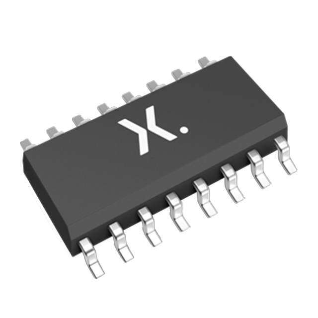
| 封装/外壳 | 16-SOIC(0.154",3.90mm 宽) |
| 封装/箱体 | SOT-109 |
| 工作温度 | -40°C ~ 125°C |
| 工厂包装数量 | 2500 |
| 最大工作温度 | + 125 C |
| 最小工作温度 | - 40 C |
| 标准包装 | 1 |
| 独立电路 | 1 |
| 电压-电源 | 2 V ~ 6 V |
| 电压源 | 单电源 |
| 电流-输出高,低 | 5.2mA,5.2mA |
| 电源电压-最大 | 6 V |
| 电源电压-最小 | 2 V |
| 电路 | 1 x 8:1 |
| 类型 | 多路复用器 |
| 输入/输出线数量 | 8 / 1 |
| 输入线路数量 | 8 |
| 输出线路数量 | 1 |
| 逻辑系列 | HC |
| 零件号别名 | 74HC251D-T |





- 商务部:美国ITC正式对集成电路等产品启动337调查
- 曝三星4nm工艺存在良率问题 高通将骁龙8 Gen1或转产台积电
- 太阳诱电将投资9.5亿元在常州建新厂生产MLCC 预计2023年完工
- 英特尔发布欧洲新工厂建设计划 深化IDM 2.0 战略
- 台积电先进制程称霸业界 有大客户加持明年业绩稳了
- 达到5530亿美元!SIA预计今年全球半导体销售额将创下新高
- 英特尔拟将自动驾驶子公司Mobileye上市 估值或超500亿美元
- 三星加码芯片和SET,合并消费电子和移动部门,撤换高东真等 CEO
- 三星电子宣布重大人事变动 还合并消费电子和移动部门
- 海关总署:前11个月进口集成电路产品价值2.52万亿元 增长14.8%




PDF Datasheet 数据手册内容提取
INTEGRATED CIRCUITS DATA SHEET For a complete data sheet, please also download: •The IC06 74HC/HCT/HCU/HCMOS Logic Family Specifications •The IC06 74HC/HCT/HCU/HCMOS Logic Package Information •The IC06 74HC/HCT/HCU/HCMOS Logic Package Outlines 74HC/HCT251 8-input multiplexer; 3-state Product specification December 1990 File under Integrated Circuits, IC06
Philips Semiconductors Product specification 8-input multiplexer; 3-state 74HC/HCT251 FEATURES The 74HC/HCT251 are the logic implementations of single-pole 8-position switches with the state of three • True and complement outputs select inputs (S ,S ,S )controlling the switch positions. 0 1 2 • Both outputs are 3-state for further multiplexer Assertion (Y) and negation (Y)outputs are both provided. expansion The output enable input (OE)is active LOW. The logic • Multifunction capability function provided at the output, when activated, is: • Permits multiplexing from n-lines to one line Y=OE.(I .S .S .S +I .S .S .S + 0 0 1 2 1 0 1 2 • Output capability: standard +I2.S0.S1.S2+I3.S0.S1.S2+ +I .S .S .S +I .S .S .S + • I category: MSI 4 0 1 2 5 0 1 2 CC +I .S .S .S +I .S .S .S ) 6 0 1 2 7 0 1 2 Both outputs are in the high impedance OFF-state (Z) GENERAL DESCRIPTION when the output enable input is HIGH, allowing multiplexer The 74HC/HCT251 are high-speed Si-gate CMOS devices expansion by tying the outputs. and are pin compatible with low power Schottky TTL (LSTTL). They are specified in compliance with JEDEC standard no. 7A. QUICK REFERENCE DATA GND = 0 V; T = 25(cid:176) C; t = t = 6 ns amb r f TYPICAL SYMBOL PARAMETER CONDITIONS UNIT HC HCT t / t propagation delay C = 15 pF; V = 5 V PHL PLH L CC I to Y 15 19 ns n I toY 17 19 ns n S to Y 20 20 ns n S toY 21 21 ns n C input capacitance 3.5 3.5 pF I C power dissipation capacitance per package notes 1and 2 44 46 pF PD Notes 1. C is used to determine the dynamic power dissipation (P inm W): PD D P = C · V 2· f +(cid:229) (C · V 2· f )where: D PD CC i L CC o f = input frequency in MHz i f = output frequency in MHz o (cid:229) (C · V 2· f )= sum of outputs L CC o C =output load capacitance in pF L V =supply voltage in V CC 2. For HC the condition is V = GND to V I CC For HCT the condition is V = GND to V - 1.5 V I CC ORDERING INFORMATION See“74HC/HCT/HCU/HCMOS Logic Package Information”. December1990 2
Philips Semiconductors Product specification 8-input multiplexer; 3-state 74HC/HCT251 PIN DESCRIPTION PIN NO. SYMBOL NAME AND FUNCTION 4, 3, 2, 1, 15, 14, 13, 12 I to I multiplexer inputs 0 7 5 Y multiplexer output 6 Y complementary multiplexer output 7 OE 3-state output enable input (active LOW) 8 GND ground (0 V) 11, 10, 9 S ,S ,S select inputs 0 1 2 16 V positive supply voltage CC Fig.1 Pin configuration. Fig.2 Logic symbol. Fig.3 IEC logic symbol. December1990 3
Philips Semiconductors Product specification 8-input multiplexer; 3-state 74HC/HCT251 FUNCTION TABLE INPUTS OUTPUTS OE S S S I I I I I I I I Y Y 2 1 0 0 1 2 3 4 5 6 7 H X X X X X X X X X X X Z Z L L L L L X X X X X X X H L L L L L H X X X X X X X L H L L L H X L X X X X X X H L L L L H X H X X X X X X L H L L H L X X L X X X X X H L L L H L X X H X X X X X L H L L H H X X X L X X X X H L L L H H X X X H X X X X L H L H L L X X X X L X X X H L L H L L X X X X H X X X L H L H L H X X X X X L X X H L L H L H X X X X X H X X L H L H H L X X X X X X L X H L L H H L X X X X X X H X L H L H H H X X X X X X X L H L L H H H X X X X X X X H L H Note 1. H = HIGH voltage level L= LOW voltage level X= don’t care Z=high impedance OFF-state Fig.4 Functional diagram. Fig.5 Logic diagram. December1990 4
Philips Semiconductors Product specification 8-input multiplexer; 3-state 74HC/HCT251 DC CHARACTERISTICS FOR 74HC For the DC characteristics see“74HC/HCT/HCU/HCMOS Logic Family Specifications”. Output capability: standard I category: MSI CC AC CHARACTERISTICS FOR 74HC GND = 0 V; t = t = 6 ns; C = 50 pF r f L T ((cid:176) C) TEST CONDITIONS amb 74HC SYMBOL PARAMETER UNIT WAVEFORMS V +25 - 40to+85 - 40to+125 CC (V) min. typ. max. min. max. min. max. t / t propagation delay 50 170 215 255 ns 2.0 Fig.6 PHL PLH I to Y 18 34 43 51 4.5 n 14 29 37 43 6.0 t / t propagation delay 55 175 220 265 ns 2.0 Fig.7 PHL PLH I toY 20 35 44 53 4.5 n 16 30 37 45 6.0 t / t propagation delay 66 205 255 310 ns 2.0 Fig.6 PHL PLH S to Y 24 41 51 62 4.5 n 19 35 43 53 6.0 t / t propagation delay 69 205 255 310 ns 2.0 Fig.7 PHL PLH S toY 25 41 51 62 4.5 n 20 35 43 53 6.0 t / t 3-state output enable time 36 140 175 210 ns 2.0 Fig.7 PZH PZL OEto Y,Y 13 28 35 42 4.5 10 24 30 36 6.0 t / t 3-state output disable time 39 140 170 210 ns 2.0 Fig.7 PHZ PLZ OEto Y,Y 14 28 35 42 4.5 11 24 30 36 6.0 t / t output transition time 19 75 95 110 ns 2.0 Figs 6 and 7 THL TLH 7 15 19 22 4.5 6 13 16 19 6.0 December1990 5
Philips Semiconductors Product specification 8-input multiplexer; 3-state 74HC/HCT251 DC CHARACTERISTICS FOR 74HCT For the DC characteristics see“74HC/HCT/HCU/HCMOS Logic Family Specifications”. Output capability: standard I category: MSI CC Note to HCT types The value of additional quiescent supply current (D I )for aunitload of 1 is given in the family specifications. CC To determineD I per input, multiply this value by the unit load coefficient shown in the table below. CC INPUT UNIT LOAD COEFFICIENT I 1.00 n S 1.50 0 S ,S 1.50 1 2 OE 1.50 AC CHARACTERISTICS FOR HCT GND = 0 V; t = t = 6 ns; C = 50 pF r f L T ((cid:176) C) TEST CONDITIONS amb 74HCT SYMBOL PARAMETER UNIT WAVEFORMS V +25 - 40to+85 - 40to+125 CC (V) min. typ. max. min. max. min. max. t / t propagation delay 22 35 44 53 ns 4.5 Fig.6 PHL PLH I to Y n t / t propagation delay 22 35 44 53 ns 4.5 Fig.7 PHL PLH I toY n t / t propagation delay 24 44 55 66 ns 4.5 Fig.6 PHL PLH S to Y n t / t propagation delay 25 44 55 66 ns 4.5 Fig.7 PHL PLH S toY n t / t 3-state output enable time 13 28 35 42 ns 4.5 Fig.7 PZH PZL OEto Y,Y t / t 3-state output disable time 14 28 35 42 ns 4.5 Fig.7 PHZ PLZ OEto Y,Y t / t output transition time 7 15 19 22 ns 4.5 Figs 6 and 7 THL TLH December1990 6
Philips Semiconductors Product specification 8-input multiplexer; 3-state 74HC/HCT251 AC WAVEFORMS (1) HC : VM=50%; VI= GND to VCC. HCT:VM= 1.3V; VI= GND to 3 V. Fig.6 Waveforms showing the multiplexer input (I )and select input (S )to output (Y)propagation delaysand n n the output transition times. (1) HC : VM=50%; VI= GND to VCC. HCT:VM= 1.3V; VI= GND to 3 V. Fig.7 Waveforms showing the multiplexer input (I )and select input (S )to output (Y)propagation delays and n n the output transition times. (1) HC : VM=50%; VI= GND to VCC. HCT:VM= 1.3V; VI= GND to 3 V. Fig.8 Waveforms showing the 3-state enable and disable times. PACKAGE OUTLINES See“74HC/HCT/HCU/HCMOS Logic Package Outlines”. December1990 7
 Datasheet下载


