ICGOO在线商城 > 集成电路(IC) > 逻辑 - 缓冲器,驱动器,接收器,收发器 > 74ALVT16245DGG,112

 Datasheet下载
- 型号: 74ALVT16245DGG,112
- 制造商: NXP Semiconductors
- 库位|库存: xxxx|xxxx
- 要求:
| 数量阶梯 | 香港交货 | 国内含税 |
| +xxxx | $xxxx | ¥xxxx |
查看当月历史价格
查看今年历史价格
74ALVT16245DGG,112产品简介:
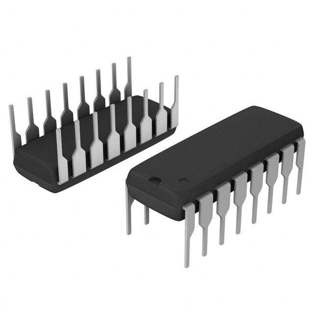
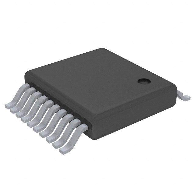
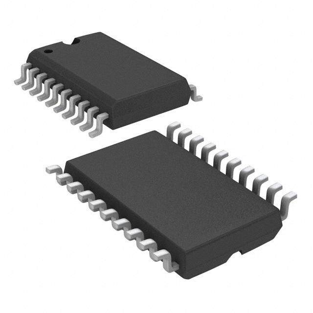
ICGOO电子元器件商城为您提供74ALVT16245DGG,112由NXP Semiconductors设计生产,在icgoo商城现货销售,并且可以通过原厂、代理商等渠道进行代购。 74ALVT16245DGG,112价格参考¥18.00-¥22.50。NXP Semiconductors74ALVT16245DGG,112封装/规格:逻辑 - 缓冲器,驱动器,接收器,收发器, Transceiver, Non-Inverting 2 Element 8 Bit per Element 3-State Output 48-TSSOP。您可以下载74ALVT16245DGG,112参考资料、Datasheet数据手册功能说明书,资料中有74ALVT16245DGG,112 详细功能的应用电路图电压和使用方法及教程。
| 参数 | 数值 |
| 产品目录 | 集成电路 (IC) |
| 描述 | IC 16BIT TXRX 3-ST 48-TSSOP |
| 产品分类 | |
| 品牌 | NXP Semiconductors |
| 数据手册 | |
| 产品图片 |
|
| 产品型号 | 74ALVT16245DGG,112 |
| PCN封装 | |
| PCN组件/产地 | |
| rohs | 无铅 / 符合限制有害物质指令(RoHS)规范要求 |
| 产品系列 | 74ALVT |
| 产品培训模块 | http://www.digikey.cn/PTM/IndividualPTM.page?site=cn&lang=zhs&ptm=24983http://www.digikey.cn/PTM/IndividualPTM.page?site=cn&lang=zhs&ptm=30632 |
| 产品目录页面 | |
| 供应商器件封装 | 48-TSSOP |
| 元件数 | 2 |
| 其它名称 | 568-2531-5 |
| 包装 | 管件 |
| 安装类型 | 表面贴装 |
| 封装/外壳 | 48-TFSOP(0.240",6.10mm 宽) |
| 工作温度 | -40°C ~ 85°C |
| 标准包装 | 39 |
| 每元件位数 | 8 |
| 电压-电源 | 2.3 V ~ 2.7 V,3 V ~ 3.6 V |
| 电流-输出高,低 | 8mA,24mA; 32mA,64mA |
| 逻辑类型 | 收发器,非反相 |


- 商务部:美国ITC正式对集成电路等产品启动337调查
- 曝三星4nm工艺存在良率问题 高通将骁龙8 Gen1或转产台积电
- 太阳诱电将投资9.5亿元在常州建新厂生产MLCC 预计2023年完工
- 英特尔发布欧洲新工厂建设计划 深化IDM 2.0 战略
- 台积电先进制程称霸业界 有大客户加持明年业绩稳了
- 达到5530亿美元!SIA预计今年全球半导体销售额将创下新高
- 英特尔拟将自动驾驶子公司Mobileye上市 估值或超500亿美元
- 三星加码芯片和SET,合并消费电子和移动部门,撤换高东真等 CEO
- 三星电子宣布重大人事变动 还合并消费电子和移动部门
- 海关总署:前11个月进口集成电路产品价值2.52万亿元 增长14.8%


PDF Datasheet 数据手册内容提取
INTEGRATED CIRCUITS 74ALVT16245 2.5V/3.3V ALVT 16-bit transceiver (3-State) Product specification 1998 Feb 13 Supersedes data of 1995 Nov 01 IC23 Data Handbook (cid:1)(cid:6)(cid:7)(cid:8)(cid:7)(cid:12)(cid:14) (cid:2)(cid:5)(cid:9)(cid:7)(cid:3)(cid:11)(cid:10)(cid:4)(cid:16)(cid:3)(cid:15)(cid:11)(cid:13)(cid:14)
Philips Semiconductors Product specification 2.5V/3.3V 16-bit transceiver (3-State) 74ALVT16245 FEATURES DESCRIPTION •16-bit bidirectional bus interface The 74ALVT16245 is a high-performance BiCMOS product • designed for VCC operation at 2.5V or 3.3V with I/O compatibility up 5V I/O Compatible to 5V. • 3-State buffers This device is a 16-bit transceiver featuring non-inverting 3-State • Output capability: +64mA/–32mA bus compatible outputs in both send and receive directions. The • control function implementation minimizes external timing TTL input and output switching levels requirements. The device features an Output Enable (OE) input for • Bus-hold data inputs eliminate the need for external pull-up easy cascading and a Direction (DIR) input for direction control. resistors to hold unused inputs • Live insertion/extraction permitted • Power-up 3-State • No bus current loading when output is tied to 5V bus • Latch-up protection exceeds 500mA per JEDEC Std 17 • ESD protection exceeds 2000V per MIL STD 883 Method 3015 and 400V per Machine Model QUICK REFERENCE DATA CONDITIONS TYPICAL SSYYMMBBOOLL PPAARRAAMMEETTEERR Tamb = 25°C 2.5V 3.3V UUNNIITT ttPPLHHL PnAroxp taog naBtiox no dr enlBaxy to nAx CL = 50pF 11..79 11..55 ns CIN Input capacitance DIR, OE VI = 0V or VCC 3 3 pF CI/O I/O pin capacitance VI/O = 0V or VCC 9 9 pF ICCZ Total supply current Outputs disabled 40 70 m A ORDERING INFORMATION PACKAGES TEMPERATURE RANGE OUTSIDE NORTH AMERICA NORTH AMERICA DWG NUMBER 48-Pin Plastic SSOP Type III –40°C to +85°C 74ALVT16245 DL AV16245 DL SOT370-1 48-Pin PlasticTSSOP Type II –40°C to +85°C 74ALVT16245 DGG AV16245 DGG SOT362-1 LOGIC SYMBOL LOGIC SYMBOL (IEEE/IEC) 1 24 1DIR 2DIR 48 25 1OE 2OE 47 2 36 13 1A0 1B0 2A0 2B0 48 G3 25 G3 1 3 EN1 (BA) 24 3 EN1 (BA) 46 3 35 14 1A1 1B1 2A1 2B1 3 EN2 (AB) 3 EN2 (AB) 44 5 33 16 1A2 1B2 2A2 2B2 47 ∇ 1 2 36 ∇ 1 13 43 6 32 17 2 ∇ 2 ∇ 1A3 1B3 2A3 2B3 46 3 35 14 44 5 33 16 41 8 30 19 1A4 1B4 2A4 2B4 43 6 32 17 41 8 30 19 40 9 29 20 1A5 1B5 2A5 2B5 40 9 29 20 38 11 27 22 38 11 27 22 1A6 1B6 2A6 2B6 37 12 26 23 37 12 26 23 1A7 1B7 2A7 2B7 SW00022 SA00021 1998 Feb 13 2 853-1817 18959
Philips Semiconductors Product specification 2.5V/3.3V 16-bit transceiver (3-State) 74ALVT16245 PIN CONFIGURATION PIN DESCRIPTION PIN NUMBER SYMBOL NAME AND FUNCTION 1DIR 1 48 1OE 1B0 2 47 1A0 1, 24 nDIR Direction control input 1B1 3 46 1A1 47, 46, 44, 43, GND 4 45 GND 41, 40, 38, 37, nA0 – nA7 Data inputs/outputs (A side) 1B2 5 44 1A2 36, 35, 33, 32, 30, 29, 27, 26 1B3 6 43 1A3 VCC 7 42 VCC 2, 3, 5, 6, 8, 9, 1B4 8 41 1A4 11, 12, 13, 14, nB0 – nB7 Data inputs/outputs (B side) 1B5 9 40 1A5 16, 17, 19, 20, 22, 23 GND 10 39 GND 1B6 11 38 1A6 25, 48 nOE Output enable input (active-Low) 1B7 12 37 1A7 4, 10, 15, 21, GND Ground (0V) 2B0 13 36 2A0 28, 34, 39, 45 2B1 14 35 2A1 7, 18, 31, 42 VCC Positive supply voltage GND 15 34 GND 2B2 16 33 2A2 FUNCTION TABLE 2B3 17 32 2A3 VCC 18 31 VCC INPUTS INPUTS/OUTPUTS 2B4 19 30 2A4 nOE nDIR nAx nBx 2B5 20 29 2A5 L L nAx = nBx Inputs GND 21 28 GND 2B6 22 27 2A6 L H Inputs nBx = nAx 2B7 23 26 2A7 H X Z Z 2DIR 24 25 2OE SA00020 H = High voltage level L = Low voltage level X = Don’t care Z = High Impedance “off” state ABSOLUTE MAXIMUM RATINGS1, 2 SYMBOL PARAMETER CONDITIONS RATING UNIT VCC DC supply voltage –0.5 to +4.6 V IIK DC input diode current VI < 0 –50 mA VI DC input voltage3 –0.5 to +7.0 V IOK DC output diode current VO < 0 –50 mA VOUT DC output voltage3 Output in Off or High state –0.5 to +7.0 V Output in Low state 128 IIOOUT DDCC oouuttppuutt ccuurrrreenntt mmAA Output in High state –64 Tstg Storage temperature range –65 to +150 °C NOTES: 1. Stresses beyond those listed may cause permanent damage to the device. These are stress ratings only and functional operation of the device at these or any other conditions beyond those indicated under “recommended operating conditions” is not implied. Exposure to absolute-maximum-rated conditions for extended periods may affect device reliability. 2. The performance capability of a high-performance integrated circuit in conjunction with its thermal environment can create junction temperatures which are detrimental to reliability. The maximum junction temperature of this integrated circuit should not exceed 150°C. 3. The input and output negative voltage ratings may be exceeded if the input and output clamp current ratings are observed. 1998 Feb 13 3
Philips Semiconductors Product specification 2.5V/3.3V 16-bit transceiver (3-State) 74ALVT16245 RECOMMENDED OPERATING CONDITIONS 2.5V RANGE LIMITS 3.3V RANGE LIMITS SSYYMMBBOOLL PPAARRAAMMEETTEERR UUNNIITT MIN MAX MIN MAX VCC DC supply voltage 2.3 2.7 3.0 3.6 V VI Input voltage 0 5.5 0 5.5 V VIH High-level input voltage 1.7 2.0 V VIL Input voltage 0.7 0.8 V IOH High-level output current –8 –32 mA Low-level output current 8 32 IIOOLL Low-level output current; current duty cycle ≤ 50%; f ≥ 1kHz 24 64 mmAA D t/D v Input transition rise or fall rate; Outputs enabled 10 10 ns/V Tamb Operating free-air temperature range –40 +85 –40 +85 °C DC ELECTRICAL CHARACTERISTICS (3.3V (cid:1)0.3V RANGE) LIMITS SYMBOL PARAMETER TEST CONDITIONS Temp = -40°C to +85°C UNIT MIN TYP1 MAX VIK Input clamp voltage VCC = 3.0V; IIK = –18mA –0.85 –1.2 V VCC = 3.0 to 3.6V; IOH = –100m A VCC–0.2 VCC VVOOHH HHiigghh--lleevveell oouuttpuutt vvoollttaaggee VV VCC = 3.0V; IOH = –32mA 2.0 2.3 VCC = 3.0V; IOL = 100m A 0.07 0.2 VCC = 3.0V; IOL = 16mA 0.25 0.4 VVOOLL LLooww––lleevveell oouuttpuutt vvoollttaaggee VV VCC = 3.0V; IOL = 32mA 0.3 0.5 VCC = 3.0V; IOL = 64mA 0.4 0.55 VCC = 3.6V; VI = VCC or GND Control pins 0.1 ±1 VCC = 0 or 3.6V; VI = 5.5V 0.1 10 II Input leakage current VCC = 3.6V; VI = 5.5V 0.1 20 m A VVCCCC == 33.66VV;; VVII == VVCCCC DDaattaa piinnss444 00.55 1100 VCC = 3.6V; VI = 0 0.1 -5 IOFF Off current VCC = 0V; VI or VO = 0 to 4.5V 0.1 ±100 m A VCC = 3V; VI = 0.8V 75 130 BBuuss HHoolldd ccuurrrreenntt IHOLD AA oorr BB ppoorrttss66 VCC = 3V; VI = 2.0V –75 –140 m A VCC = 0V to 3.6V; VCC = 3.6V ±500 IEX CHuigrhre sntta itnet ow ahne no uVtOp u>t VinC tChe VO = 5.5V; VCC = 3.0V 50 125 m A IPU/PD Pcuorwreenr tu3p/down 3-State output VOCEC/O ≤E 1 =.2 DV;o Vn’Ot c=a 0re.5V to VCC; VI = GND or VCC; 40 ±100 m A ICCH VCC = 3.6V; Outputs High, VI = GND or VCC, IO = 0 0.07 0.1 ICCL Quiescent supply current VCC = 3.6V; Outputs Low, VI = GND or VCC, IO = 0 3.2 5 mA ICCZ VCC = 3.6V; Outputs Disabled; VI = GND or VCC, IO = 05 0.07 0.1 D ICC Aindpduitt ipoinna2l supply current per VOCthCe =r i3nVpu ttos 3a.t6 VVC; CO noer GinNpDut at VCC–0.6V, 0.2 0.4 mA NOTES: 1. All typical values are at VCC = 3.3V and Tamb = 25°C. 2. This is the increase in supply current for each input at the specified voltage level other than VCC or GND 3. This parameter is valid for any VCC between 0V and 1.2V with a transition time of up to 10msec. From VCC = 1.2V to VCC = 3.3V ±0.3V a transition time of 100m sec is permitted. This parameter is valid for Tamb = 25°C only. 4. Unused pins at VCC or GND. 5. ICCZ is measured with outputs pulled up to VCC or pulled down to ground. 6. This is the bus hold overdrive current required to force the input to the opposite logic state. 1998 Feb 13 4
Philips Semiconductors Product specification 2.5V/3.3V 16-bit transceiver (3-State) 74ALVT16245 AC CHARACTERISTICS (3.3V (cid:1)0.3V RANGE) GND = 0V; tR = tF = 2.5ns; CL = 50pF; RL = 500W ; Tamb = –40°C to +85°C. LIMITS SYMBOL PARAMETER WAVEFORM VCC = 3.3V (cid:1)0.3V UNIT MIN TYP1 MAX tPLH Propagation delay 1 0.5 1.5 2.4 ns tPHL nAx to nBx or nBx to nAx 0.5 1.5 2.4 tPZH Output enable time 2 1.0 2.1 3.5 ns tPZL to High and Low level 1.0 1.7 2.9 tPHZ Output disable time 2 1.5 3.4 4.5 ns tPLZ from High and Low Level 1.5 2.8 3.7 NOTE: 1. All typical values are at VCC = 3.3V and Tamb = 25°C. DC ELECTRICAL CHARACTERISTICS (2.5V (cid:1)0.2V RANGE) LIMITS SYMBOL PARAMETER TEST CONDITIONS Temp = -40°C to +85°C UNIT MIN TYP1 MAX VIK Input clamp voltage VCC = 2.3V; IIK = –18mA –0.85 –1.2 V VCC = 2.3 to 3.6V; IOH = –100m A VCC–0.2 VVOOHH HHiigghh--lleevveell oouuttpuutt vvoollttaaggee VV VCC = 2.3V; IOH = –8mA 1.8 2.1 VCC = 2.3V; IOL = 100m A 0.07 0.2 VOL Low-level output voltage VCC = 2.3V; IOL = 24mA 0.3 0.5 V VCC = 2.3V; IOL = 8mA 0.4 VCC = 2.7V; VI = VCC or GND Control pins 0.1 ±1 VCC = 0 or 2.7V; VI = 5.5V 0.1 10 II Input leakage current VCC = 2.7V; VI = 5.5V 0.1 20 m A VCC = 2.7V; VI = VCC Data pins44 0.1 10 VCC = 2.7V; VI = 0 0.1 -5 IOFF Off current VCC = 0V; VI or VO = 0 to 4.5V 0.1 ±100 m A IIHHOOLLDD BDuasta H inopldu tcsu6rrent VVCCCC == 22..33VV;; VVII == 01..77VV –9100 mm AA IEX CHuigrhre sntta itnet ow ahne no uVtOp u>t VinC tChe VO = 5.5V; VCC = 2.3V 50 125 m A IPU/PD Pcuorwreenr tu3p/down 3-State output VOCEC/O ≤E 1 =.2 DV;o Vn’Ot c=a 0re.5V to VCC; VI = GND or VCC; 40 100 m A ICCH VCC = 2.7V; Outputs High, VI = GND or VCC, IO = 0 0.04 0.1 ICCL Quiescent supply current VCC = 2.7V; Outputs Low, VI = GND or VCC, IO = 0 2.3 45 mA ICCZ VCC = 2.7V; Outputs Disabled; VI = GND or VCC, IO = 05 0.04 0.1 D ICC Aindpduitt ipoinna2l supply current per VOCthCe =r i2n.p3uVts t oa t2 V.7CVC; oOrn Ge NinDput at VCC–0.6V, 0.1 0.4 mA NOTES: 1. All typical values are at VCC = 2.5V and Tamb = 25°C. 2. This is the increase in supply current for each input at the specified voltage level other than VCC or GND 3. This parameter is valid for any VCC between 0V and 1.2V with a transition time of up to 10msec. From VCC = 1.2V to VCC = 2.5V ±0.3V a transition time of 100m sec is permitted. This parameter is valid for Tamb = 25°C only. 4. Unused pins at VCC or GND. 5. ICCZ is measured with outputs pulled up to VCC or pulled down to ground. 6. Not guaranteed. 1998 Feb 13 5
Philips Semiconductors Product specification 2.5V/3.3V 16-bit transceiver (3-State) 74ALVT16245 DYNAMIC SWITCHING THRESHOLD Dynamic switching threshold is the change in VIH and VIL when the device is operated in various switching and output loading conditions. The cause of this variation is due to extra load placed on internal circuit structures. VIHD and VILD are measures of the dynamic switching threshold. VIHD is the input high switching level when the device is heavily loaded. VILD is the input low switching level when the device is heavily loaded. V /V vs V V /V vs Frequency ILD IHD CC ILD IHD Temp = 25°C Vild/Vihd vs VCC 3.0 Vild/Vihd vs Frequency – T = 25°C 3.00 2.5 Input Dynamic Threshold Voltage (V) 0112....5050 - - - - VViihldd Input Dynamic Threshold Voltage (V) 1122....05050000 - - - - VViihldd 0.50 0.0 2.3 2.5 2.7 3.0 3.3 3.6 0.00 VCC (V) SA00455 5 20 40 60 80 100 120 Frequency (MHz) SA00456 GROUND/V BOUNCE CC VOLP vs Temperature VOLP vs Capacitive Load 2.0 1.0 1.8 0.9 1.6 0.8 1.4 0.7 V) 1.2 V) 0.6 (VOLP 10..08 (VOLP 00..54 0.6 0.3 0.4 0.2 0.2 0.1 0.0 0.0 –55 –40 25 85 125 50pF 150pF 270pF Temperature (°C) SA00457 Capacitive Load (pF) SA00459 VOHV vs Temperature VOHV vs Capacitive Load 4.0 4.0 3.5 3.5 3.0 3.0 2.5 V) V) (HV 2.5 (HV 2.0 O O V V 1.5 2.0 1.0 1.5 0.5 1.0 0.0 150pF 270pF –55 –40 25 85 125 50pF Temperature (°C) SA00458 Capacitive Load (pF) SA00460 1998 Feb 13 6
Philips Semiconductors Product specification 2.5V/3.3V 16-bit transceiver (3-State) 74ALVT16245 AC CHARACTERISTICS (2.5V (cid:1)0.2V RANGE) GND = 0V; tR = tF = 2.5ns; CL = 50pF; RL = 500W ; Tamb = –40°C to +85°C. LIMITS SYMBOL PARAMETER WAVEFORM VCC = 2.5V (cid:1)0.2V UNIT MIN TYP1 MAX tPLH Propagation delay 1 0.5 1.7 2.8 ns tPHL nAx to nBx or nBx to nAx 0.5 1.9 2.8 tPZH Output enable time 2 1.5 3.0 4.5 ns tPZL to High and Low level 1.0 2.3 3.5 tPHZ Output disable time 2 1.5 3.0 4.6 ns tPLZ from High and Low Level 1.0 2.3 3.5 NOTE: 1. All typical values are at VCC = 2.5V and Tamb = 25°C. SKEW DATA tps (Pin Skew or Transition Skew) tPS = | tPHL – tPLH | VCC = 2.3 VCC = 2.5 VCC = 2.7 VCC = 3.0 VCC = 3.3 VCC = 3.6 UNITS tPS Max 429 469 430 426 267 336 ps tOST = | tP(cid:1)m – tP(cid:1)n | Where (cid:1) is any edge transition (high-to-low or low-to-high) measured between any two outputs (m or n) within any given device. VCC = 2.3 VCC = 2.5 VCC = 2.7 VCC = 3.0 VCC = 3.3 VCC = 3.6 UNITS tOST nAn-nBn 546 625 586 546 427 397 pss nBn-nAn 508 547 586 506 427 417 NOTE: One output switching, Temp = 25°C. tOSHL, tOSLH, (Common Edge Skew) tOSHL = | tPHL max – tPHL min | (Output Skew for Low-to-High Transitions) tOSLH = | tPLH max – tPLH min | (Output Skew for High-to-Low Transitions) VCC = 2.3 VCC = 2.5 VCC = 2.7 VCC = 3.0 VCC = 3.3 VCC = 3.6 UNITS tOSLH nAn-nBn 312 312 313 276 267 257 tOSHL nAn-nBn 312 352 352 297 289 267 pss tOSLH nBn-nAn 235 273 312 274 296 326 tOSHL nBn-nAn 234 235 274 248 287 267 NOTE: One output switching, Temp = 25°C. 1998 Feb 13 7
Philips Semiconductors Product specification 2.5V/3.3V 16-bit transceiver (3-State) 74ALVT16245 EXTENDED DATA TPHL vs TEMP TPLH vs NUMBER of OUTPUTS SWITCHING VCC = 3.3V, one output switching T = 25°C, 50pF/500 ohm load 2.00 4.00 1.90 VCC = 2.3V 1.80 3.50 1.70 S) S) 3.00 n 1.60 n L ( H ( H 1.50 L 2.50 P P T 1.40 T 1.30 2.00 VCC = 3.6V 1.20 1.50 1.10 1.00 1.00 –55 –40 25 85 125 1 8 16 Temperature (°C) Number of Outputs Switching SA00452 SA00449 TPHL vs NUMBER of OUTPUTS SWITCHING TPLH vs TEMP T = 25°C, 50pF/500 ohm load VCC = 3.3V, one output switching 3.00 2.00 2.80 1.90 2.60 1.80 2.40 VCC = 2.3V 1.70 S) H (nS) 11..6500 PHL (n 22..2000 L T 1.80 P 1.40 T 1.60 1.30 VCC = 3.6V 1.40 1.20 1.20 1.10 1.00 1.00 1 8 16 –55 –40 25 85 125 Number of Outputs Switching Temperature (°C) SA00453 SA00450 TPHL vs OUTPUT LOAD TPLH vs OUTPUT LOAD Outputs also loaded with 500 ohms to ground, T= 25°C Outputs also loaded with 500 ohms to ground, T= 25°C 4.00 6.00 3.50 16 Outputs Swicthing 5.00 3.00 16 Outputs Switching S) 1 Output Switching n 2.50 S) 4.00 HL ( n P 2.00 H ( 3.00 T L 1 Output Switching 1.50 P T 2.00 1.00 1.00 0.50 0.00 0.00 150pF 50pF 150pF 270pF 50pF 270pF Capacitive Load (pF) Capacitive Load (F) SA00454 SA00451 1998 Feb 13 8
Philips Semiconductors Product specification 2.5V/3.3V 16-bit transceiver (3-State) 74ALVT16245 AC WAVEFORMS VM = 1.5V at VCC (cid:2) 3.0V, VM = VCC/2 at VCC (cid:1) 2.7V VX = VOL + 0.3V at VCC (cid:2) 3.0V, VX = VOL + 0.15V at VCC (cid:1) 2.7V VY = VOH – 0.3V at VCC (cid:2) 3.0V, VY = VOH – 0.15V at VCC (cid:1) 2.7V 3.0V or VCC 3.0V or VCC whichever AINnP oUr TBn VM VM wish leicshsever OE INPUT VM VM is less 0V 0V tPZL tPLZ 6.0V or tPLH tPHL VCC x 2 VOH OUTPUT VM Bn or An VX OUTPUT VM 1.5V or VCC/2 tPZH tPHZ VOL VOL VOH VM = 1.5V or VCC/2, whichever is less SW00023 VY OUTPUT VM Waveform 1. Input to Output Propagation Delays 0V SW00024 Waveform 2. 3-State Output Enable and Disable Times TEST CIRCUIT AND WAVEFORMS VCC 6.0V or VCC x 2 tW VIN 90% 90% Open NEGATIVE VM VM VIN VOUT RL GND PULSE 10% 10% 0V PULSE GENERATOR D.U.T. tTHL (tF) tTLH (tR) RT CL RL tTLH (tR) tTHL (tF) VIN 90% 90% POSITIVE PULSE VM VM Test Circuit for 3-State Outputs 10% 10% tW 0V SWITCH POSITION TEST SWITCH tPLZ/tPZL 6V or VCC x 2 tPLH/tPHL Open tPHZ/tPZH GND INPUT PULSE REQUIREMENTS DEFINITIONS FAMILY RL = Load resistor; see AC CHARACTERISTICS for value. Amplitude Rep. Rate tW tR tF CL = Load capacitance includes jig and probe capacitance: 74ALVT16 3w.0hVic ohre VveCrC (cid:1)10MHz 500ns (cid:1)2.5ns (cid:1)2.5ns See AC CHARACTERISTICS for value. is less RT = Termination resistance should be equal to ZOUT of pulse generators. SW00025 1998 Feb 13 9
Philips Semiconductors Product specification 2.5V/3.3V ALVT 16-bit transceiver (3-State) 74ALVT16245 SSOP48: plastic shrink small outline package; 48 leads; body width 7.5mm SOT370-1 1998 Feb 13 10
Philips Semiconductors Product specification 2.5V/3.3V ALVT 16-bit transceiver (3-State) 74ALVT16245 TSSOP48: plastic thin shrink small outline package; 48 leads; body width 6.1mm SOT362-1 1998 Feb 13 11
Philips Semiconductors Product specification 2.5V/3.3V ALVT 16-bit transceiver (3-State) 74ALVT16245 Data sheet status Data sheet Product Definition [1] status status Objective Development This data sheet contains the design target or goal specifications for product development. specification Specification may change in any manner without notice. Preliminary Qualification This data sheet contains preliminary data, and supplementary data will be published at a later date. specification Philips Semiconductors reserves the right to make chages at any time without notice in order to improve design and supply the best possible product. Product Production This data sheet contains final specifications. Philips Semiconductors reserves the right to make specification changes at any time without notice in order to improve design and supply the best possible product. [1] Please consult the most recently issued datasheet before initiating or completing a design. Definitions Short-form specification — The data in a short-form specification is extracted from a full data sheet with the same type number and title. For detailed information see the relevant data sheet or data handbook. Limiting values definition — Limiting values given are in accordance with the Absolute Maximum Rating System (IEC 134). Stress above one or more of the limiting values may cause permanent damage to the device. These are stress ratings only and operation of the device at these or at any other conditions above those given in the Characteristics sections of the specification is not implied. Exposure to limiting values for extended periods may affect device reliability. Application information — Applications that are described herein for any of these products are for illustrative purposes only. Philips Semiconductors make no representation or warranty that such applications will be suitable for the specified use without further testing or modification. Disclaimers Life support — These products are not designed for use in life support appliances, devices or systems where malfunction of these products can reasonably be expected to result in personal injury. Philips Semiconductors customers using or selling these products for use in such applications do so at their own risk and agree to fully indemnify Philips Semiconductors for any damages resulting from such application. Right to make changes — Philips Semiconductors reserves the right to make changes, without notice, in the products, including circuits, standard cells, and/or software, described or contained herein in order to improve design and/or performance. Philips Semiconductors assumes no responsibility or liability for the use of any of these products, conveys no license or title under any patent, copyright, or mask work right to these products, and makes no representations or warranties that these products are free from patent, copyright, or mask work right infringement, unless otherwise specified. Philips Semiconductors Copyright Philips Electronics North America Corporation 1998 811 East Arques Avenue All rights reserved. Printed in U.S.A. P.O. Box 3409 Sunnyvale, California 94088–3409 print code Date of release: 05-96 Telephone 800-234-7381 Document order number: 9397-750-03647 (cid:1)(cid:6)(cid:7)(cid:8)(cid:7)(cid:12)(cid:14) (cid:2)(cid:5)(cid:9)(cid:7)(cid:3)(cid:11)(cid:10)(cid:4)(cid:16)(cid:3)(cid:15)(cid:11)(cid:13)(cid:14) yyyy mmm dd 12