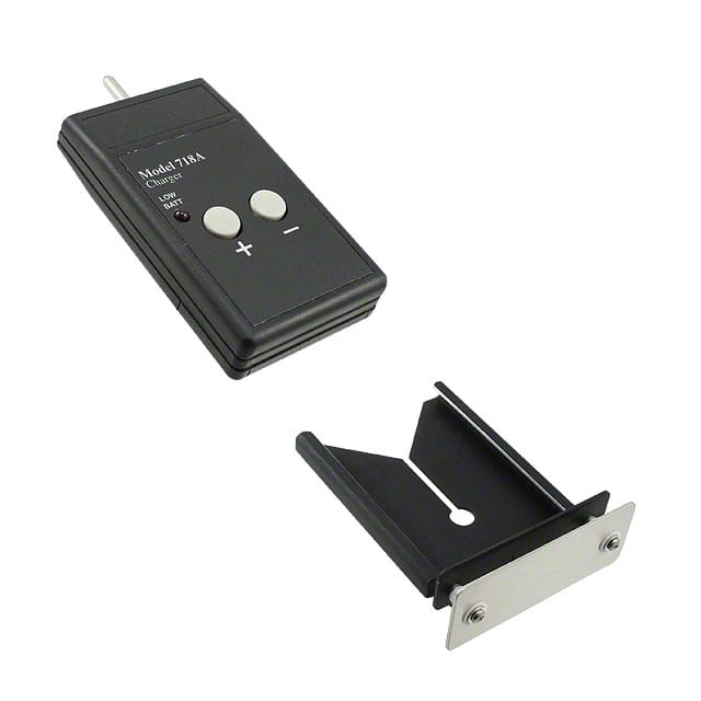
ICGOO在线商城 > 718A
- 型号: 718A
- 制造商: 3M
- 库位|库存: xxxx|xxxx
- 要求:
| 数量阶梯 | 香港交货 | 国内含税 |
| +xxxx | $xxxx | ¥xxxx |
查看当月历史价格
查看今年历史价格
718A产品简介:
ICGOO电子元器件商城为您提供718A由3M设计生产,在icgoo商城现货销售,并且可以通过原厂、代理商等渠道进行代购。 提供718A价格参考以及3M718A封装/规格参数等产品信息。 你可以下载718A参考资料、Datasheet数据手册功能说明书, 资料中有718A详细功能的应用电路图电压和使用方法及教程。
| 参数 | 数值 |
| 产品目录 | |
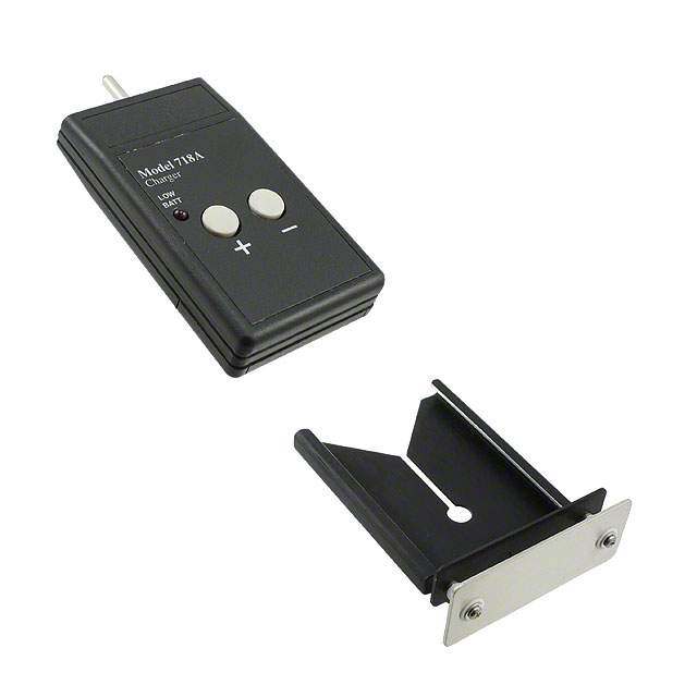
| 描述 | AIR IONIZER TEST KIT防静电控制产品 ACCESS PK W/CHARGER |
| 产品分类 | |
| 品牌 | 3M |
| 产品手册 | |
| 产品图片 |
|
| rohs | 否不适用 / 不适用 |
| 产品系列 | 3M Electronic Specialty 718A718A |
| mouser_ship_limit | Mouser目前不销售该产品。 |
| 数据手册 | http://multimedia.3m.com/mws/mediawebserver?6666660Zjcf6lVs6EVs666BODCOrrrrQ-http://multimedia.3m.com/mws/mediawebserver?66666UuZjcFSLXTtlX&6LxfEEVuQEcuZgVs6EVs6E666666-- |
| 产品型号 | 718A |
| 产品 | Sensors |
| 产品种类 | 防静电控制产品 |
| 其它名称 | 0-00-51138-71633-2 |
| 其它有关文件 | |
| 单位重量 | 1.814 kg |
| 商标 | 3M Electronic Specialty |
| 大小 | 0.85 in x 2.4 in x 5 in |
| 安装类型 | 台式,便携式 |
| 工具箱 | /product-detail/zh/752/7523M-ND/3863621/product-detail/zh/751/751-ND/3863620 |
| 描述/功能 | Easy to use, hand-held instrument designed to measure static voltages on objects |
| 标准包装 | 1 |
| 特色产品 | http://www.digikey.cn/product-highlights/zh/3m-static-control/52176http://www.digikey.cn/product-highlights/zh/3m-air-ionizers/52895 |
| 电压-输入 | - |
| 电缆类型 | Cord Type US |
| 类型 | Static |
| 零件号别名 | 05113871633 98079845065 |
| 颜色 | Black |




- 商务部:美国ITC正式对集成电路等产品启动337调查
- 曝三星4nm工艺存在良率问题 高通将骁龙8 Gen1或转产台积电
- 太阳诱电将投资9.5亿元在常州建新厂生产MLCC 预计2023年完工
- 英特尔发布欧洲新工厂建设计划 深化IDM 2.0 战略
- 台积电先进制程称霸业界 有大客户加持明年业绩稳了
- 达到5530亿美元!SIA预计今年全球半导体销售额将创下新高
- 英特尔拟将自动驾驶子公司Mobileye上市 估值或超500亿美元
- 三星加码芯片和SET,合并消费电子和移动部门,撤换高东真等 CEO
- 三星电子宣布重大人事变动 还合并消费电子和移动部门
- 海关总署:前11个月进口集成电路产品价值2.52万亿元 增长14.8%

PDF Datasheet 数据手册内容提取
USER GUIDE TB-9016 718 Static Sensor Installation, Operation and Maintenance Made in the United States of America 7. The SCS Static Sensor 718 has a Low Battery indicator. Once the battery is depleted to approximately 6.5 volts, the instrument will show BAT in the display. At this time, the Static Sensor 718 will not produce accurate results and the battery should be replaced. 8. The SCS Charger 718A also has a low battery indicator. This is an LED located at the left-hand side of the unit. When the battery voltage drops below operating level, the LED will light up. At this time, the user shouldreplace the battery. Usage of the Charger 718A under low battery conditions would lead to insufficient voltage levels being generated. Figure 1. (Left to right) SCS 718 Static Sensor and SCS 718A Air Ionizer Test Kit. Description The SCS Static Sensor 718 is a portable handheld instrument used for locating and measuring electrostatic charges. It can be used to locate ESD trouble-areas, and is a valuable tool for the ESD-control engineer. Used in conjunction with the SCS Air Ionizer Test Kit 718A (sold separately), it can be used for verification and auditing of air ionizers. The Static Sensor 718 is battery-powered Figure 2. SCS 718 and 718A Battery Replacement and has several measurement features: and Indicators. Range: measurements can be taken in a 0 to ±1.999 kV Operation of the Static Sensor 718 or 0 to ±19.99 kV range. For accurate measurements during usage, it is Automatic Zero: push button feature allows easy recommended that the outside housing of the Static adjustment to zero. No screws or dials to turn. Sensor 718 be connected to an electrical ground. This can be accomplished by having the user holding HOLD function: allows the User to “freeze” a displayed the instrument connected to ground through either a measurement, for later evaluation. static control wrist strap, or while wearing static control footwear. The enclosure of the Static Sensor 718 is Automatic shutoff: conserves battery power by shutting made of conductive plastic and is, therefore, electrically off the instrument after 20 minutes of inactivity. connected to whomever is holding the instrument. In addition, ground for the instrument can be provided Power Requirements and Battery Installation through the Voltage Monitor Output on the front of the 1. Both the Static Sensor 718 and SCS Charger 718A case. use a 9V alkaline battery. 2. To install the battery on either unit: The SCS Static Sensor 718 is a precision electronic 3. Remove the battery cover, located in the lower back instrument. Improper use or rough treatment can of the unit. To do this, press down on the cover and damage the unit, and render it incapable of providing slide it downward. accurate measurements. 4. Pull the battery connector out of the housing, and align the male/female ends of the connector with the Turning the unit ON and OFF: To turn on the Static proper terminals on the battery. Sensor 718, momentarily press down on the membrane 5. Connect the two and place the connected battery switch labeled POWER. Determining that the power into the housing by inserting the connector end first, is on can be verified by seeing that the liquid crystal then following up with the other end of the battery. display (LCD) is on, and that the red light-emitting diodes 6. Replace the cover. in the front of the sensor are lit. SCS - 926 JR Industrial Drive, Sanford, NC 27332 • (919) 718-0000 • Website: StaticControl.com TB-9016 Page 1 of 6 January 2016 © 2016 DESCO INDUSTRIES, INC. Employee Owned
To shut off the Static Sensor 718, momentarily press known zero-voltage surface, and holding down the down on the membrane switch labeled POWER. RANGE/ZERO button for longer than 3 seconds. After Determining that the power is off can be verified by 3 seconds, the display will flash and adjust to zero. seeing that the liquid-crystal display (LCD) is off. Repeat this step for both the low and the high ranges. The zero adjustment should be performed every time the unit is turned on. Making Electrostatic Voltage Measurements: hold the instrument 1-inch (2.54 cm) away from the object Measurement Accuracy: Distance Indicator: the being measured. The display will update with the voltage Static Sensor 718 is factory calibrated to give accurate measurement in kilovolts. If the measured voltage is measurements when it is placed one inch (2.54 cm) greater than the measurement range of the instrument, away from the object to be measured. To assist the a -1. Will be displayed. At this time, switch to a greater user in gauging this distance, two light-emitting diodes range. If over-ranging occurs even with the high range (LED’s) are present on the front face of the instrument. activated, the static charge on the object cannot be These LED’s emit two red, bull’s-eye targets on the measured with the Static Sensor 718. surface of the object being measured. As the instrument gets closer to the one inch measurement distance, the bull’s-eyes begin to converge. When they converge and become one, the instrument is approximately one inch away, and the measurement can be made. For more accurate measurements, it is recommended that the user manually measure the distance between the front housing of the instrument and the object being measured. Accuracy and Size of Object to be Measured: the minimum surface area on an electrostatically charged Figure 3. Using 718 Static Sensor to take measurements. object which can be accurately measured is a 5 square inch (32.3 cm2) area. Measurement Range: all measurements are in kilovolts (kV) as stated on the front label of the unit. The Static Measurements from Greater than One Inch (2.54 cm) Sensor 718 has two measurement ranges: 0 to ±1.999 Away: in the event that a one inch separation between kV and 0 to ±19.99 kV. The unit’s current measurement object-to-be measured and the Static Sensor 718 cannot range mode can be verified by checking the display. be achieved, it is possible to get approximate readings. Three digits following the decimal point indicate that the unit is in 0 to ±1.999 kV range. Two digits following the Continuous Output: an output jack is provided on decimal point indicate that the sensor is in 0 to ±19.99 kV range. To change between measurement ranges, press the RANGE/HOLD button once, momentarily. HOLD Function: in the event that the user wishes to freeze the current measurement, the HOLD function of the Static Sensor 718 may be used. Simply press the HOLD switch momentarily and the currently displayed voltage will be frozen. A HOLD notice will also be displayed to alert the user that the instrument is currently in HOLD status. To unfreeze the display and return to Figure 5. 718 Static Sensor has a continuos output range. floating measurement, momentarily press the HOLD switch once again. the front of the SCS Static Sensor 718. This output Note: During HOLD condition the distance indicating can be used to feed a continuous signal into a data LED’s are turned off. storage device for continuous monitoring of measured voltages. Please use a 3/32 inch (2.5 mm) mono-phone Zero Adjustment: the SCS Static Sensor 718 has a plug to connect into the output jack. The output signal zero adjustment function, which sets a zero reference is dependent on the measurement range currently point for all subsequent measurements. This zero selected. For the low range, the output signal is 1/1000 reference can be set by pointing the instrument at a of the measured electrostatic voltage. For the high range, the output signal is 1/10,000 of the measured voltage. Figure 4. 718 Static Sensor showing hold function and floating measurement function. SCS - 926 JR Industrial Drive, Sanford, NC 27332 • (919) 718-0000 • Website: StaticControl.com TB-9016 Page 2 of 6 © 2016 DESCO INDUSTRIES, INC. Employee Owned
Automatic Shut-Off: the Static Sensor 718 will automatically shut-off 20 minutes after the last switch activity. This is done in order to conserve battery power. In the event that the user needs to have the unit stay ON continuously, when turning the unit on press the POWER AND RANGE switches simultaneously. This deactivates the Automatic Shut-Off feature. The BAT indicator will then flash three times to indicate that the automatic shut- off features has been disabled. The Automatic Shut-Off feature will reset itself the next time the instrument is Figure 7. Testing Ionizer Offset Balance. turned on. Testing Ionizer Discharge Time: after charging the Operation and Use of SCS Air Ionizer plate, hold the SCS Static Sensor 718 approximately one foot (30.5 cm) away from the ionizer. Monitor the display Kit 718A to see how quickly the 1.1 kV charge is dissipated to It is recommended that the user be familiar with ionizer 0.1 kV. The speed at which this occurs (the discharge test standards ANSI/ESD S3.1 and draft standard ANSI/ time) indicates how well the ionizer is operating. Please ESD SP3.3 if the Air Ionizer Test Kit 718A is used to refer to the specific ionizer’s operating manual or consult perform verification testing on ionizer performance. with the ionizer manufacturer to determine what this discharge time should be. Repeat this procedure for both Assembly: slide the charge plate over the Static Sensor a positively and a negatively charged plate. 718 until it stops. The charge plate slides onto the lower groove, on the sides of the Static Sensor 718. Testing ionizer offset balance: zero the charge plate by touching it with a grounded object. This can either be the finger of a grounded person or some other item which is connected to electrical ground. In either case, zeroing the charge plate should make the display on the Static Sensor 718 read zero. Hold the Static Sensor 718 approximately one foot (30.5 cm) in front of the ionizer. Monitor the display. The value displayed is the offset balance of the ionizer, which is the difference between the number of positive and negative ions being emitted. Please refer to the specific ionizer’s operating manual or Figure 6. 718 Static Sensor charging plate in use. consult with the ionizer manufacturer to determine what this offset balance should be. Charging the Plate: holding the Static Sensor 718 (with charge plate attached) in one hand, use the other hand Service/Calibration to touch the probe of the SCS Air Ionizer Test Kit 718A to the charge plate. Press either the + button (for a Service and Repair: in the event that you believe the positive voltage) or the – button (for a negative voltage), Static Sensor 718 or the SCS Air Ionizer Test Kit 718A then remove the probe from the charge plate. Be sure is in need of repair, please contact your local SCS to keep the button pressed while removing the probe representative for troubleshooting help, and, as needed, from the charge plate. The display on the Static Sensor repair information. There are no user-serviceable parts 718 will indicate a positive or negative charging voltage on either product. (1.1kV minimum). If a voltage of less than ±1.1kV is displayed, check to see if the low battery indicator on the SCS Charger 718A is illuminated. If illuminated, replace the battery in the charger. If the unit continues to supply an incorrect voltage to the charge plate, please contact SCS for additional instructions. Testing ionizer discharge time: after charging the plate, hold the SCS Static Sensor 718 approximately one foot (30.5 cm) away from the ionizer. Monitor the display to see how quickly the 1.1 kV charge is dissipated to 0.1 kV. The speed at which this occurs (the discharge time) indicates how well the ionizer is operating. Please refer to the specific ionizer’s operating manual or consult Figure 8. 718 Static Sensor on test fixture. with the ionizer manufacturer to determine what this discharge time should be. Repeat this procedure for both a positively and a negatively charged plate. SCS - 926 JR Industrial Drive, Sanford, NC 27332 • (919) 718-0000 • Website: StaticControl.com TB-9016 Page 3 of 6 © 2016 DESCO INDUSTRIES, INC. Employee Owned
Calibration: the SCS Static Sensor 718 and SCS Air SCS Static Sensor 718 Specifications Ionizer Test Kit 718A products are supplied by the (All values typical) factory pre-calibrated. SCS does not specify a minimum calibration cycle for the Static Sensor 718 or Air Ionizer (At 1in. (2.54cm) distance from sensor to target) Test Kit 718A products. The user, usually according to internal Quality procedures, determines calibration Dimensions 0.85" H x 2.4" W x 4.2" L cycles. In the event that the user wishes to perform a 2.2 cm H x 6.1 cm W x 10.6 cm L self-calibration, the following steps should be followed for the Static Sensor 718 (user-calibration not possible Weight 4.4 oz. (125 g) with battery on the Air Ionizer Test Kit 718A). Equipment Needed: Test Fixture High-Voltage Power Operating 41º F - 95º F (5º C - 35º C) Supply, capable of supplying voltages up to 10,000V. Conditions Up to 80% RH, non-condensing Voltmeter, with > 50 kilohms input impedance, capable Indoor use only of measuring voltages down to the μV range. Cable For use at altitudes below 6,562 ft. with a 3/32 inch (2.5 mm) mono plug and secondary (2,000 m). connector to interface with voltmeter. Pollution Degree II Class III Test Fixture: Metal plate of at least 5 square inches area (38.7 cm2) area. Metal stand capable of supporting Enclosure Conductive Housing Static Sensor 718, and holding it one inch (2.54 cm) away from the metal plate, centered. Connectors on the Power 1 - 9 volt alkaline battery plate with which it can interface with the high voltage Requirements power supply. Connections on the metal stand with which it can be connected to electrical ground. Measurement Low Range: 0 to ±1.999 kV / inch Ranges High Range: 0 to ±19.99 kV / inch Procedure: Place the Static Sensor Static Sensor 718 on the metal stand. Verify that it is exactly one Voltage Display Liquid Crystal Display inch (2.54 cm) away from the metal plate, and that its position is centered relative to the plate. Connect the stand to ground. Turn on the Static Sensor 718 and set Display 1V/inch (0.39V/cm) @ low range it to the low range. Ground the plate. Zero the display. Resolution 10V/inch (3.9V/cm) @ high range Remove the ground from the plate, and connect it to the ± 10 counts high voltage power supply. Apply a 1 kV charge to the plate. Voltage Output 3/32 in. (2.5 mm)mono phone Jack Tip: signal The instrument should now be reading 1.000. If it is not, Sleeve: ground remove the battery door and use a screwdriver to turn the small screw located inside the battery compartment. Voltage Output 1/1000 of measured Use a small screwdriver to turn the small screw, located voltage @ low range on the front right side of the instrument. This screw should adjust the reading on the display. Once the 1/10,000 of measured display has been adjusted to read 1.000, the low range voltage @ high range of the SCS Static Sensor 718 is now calibrated. Repeat procedures 5.5.2 - 5.5.6 for the high of the meter, using Automatic Shutoff 20 minutes after last switch activity a test voltage of 5,000 volts. Distance Indicator LED targets. Aligned targets indicate 1in. (2.54 cm) measurement distance. Measurement ± 10 counts Stability Certifications cULus, CE Figure 9. 718 Static Sensor adjustable screw for display. SCS - 926 JR Industrial Drive, Sanford, NC 27332 • (919) 718-0000 • Website: StaticControl.com TB-9016 Page 4 of 6 © 2016 DESCO INDUSTRIES, INC. Employee Owned
SCS Air Ionizer 718A Specifications The SCS Air Ionizer Test Kit 718A is a set of accessories for use in conjunction with the Static Sensor (All values typical) 718. Their intended use is for verifying the operation (At 1in. (2.54cm) distance from sensor to target) of air ionizers by measuring the neutralization time for a static charge placed on a stationary metal plate. Charge Plate Per ESD Association Draft Any deviation from this intended use could impair the Assembly Standard ANSI/ESD SP3.3. instrument’s effectiveness and possibly lead to an Aluminum bracket, bare unsafe operating condition. stainless steel plate and teflon spacers isolate plate from Caution: bracket The Static Sensor 718 and SCS Charger 718A use 9VDC power supplied by a 9V alkaline battery. Usage of any other power source may cause damage to the Voltage Output 1/1000 of measured instruments. voltage @ low range 1/10,000 of measured The Static Sensor 718 and Air Ionizer Test Kit 718A voltage @ high range have no user-serviceable parts. Do not disassemble the products for any reason. UNAUTHORIZED SERVICE Charge Plate Area 3.25" W x 1.25" L WILL VOID THE WARRANTY. 8.3 cm W x 3.2 cm L The Static Sensor 718 and Charger 718A are NOT Charge Plate 2.5 oz. (70 g) designed for usage in hazardous environments where Assembly Weight the possibility of explosion or fire exists. Regulatory Information Charger 0.87" H x 2.4" W x 4.9" L Dimensions 2.2 cm H x 6.1 cm W x 12.4 WEEE Statement cm L The following information is only for EU-members States: The mark shown to the right is in compliance with Waste Electrical and Electronic Equipment Charger Weight 5 oz. (140 g) with battery Directive 2002/96/EC (WEEE). The mark indicates the requirement NOT to dispose the equipment as unsorted Charger Power 1 - 9 volt alkaline battery municipal waste, but use the return and collection Requirements systems according to local law. Charger Output 1.1kV minimum for +/- voltage cULus Statement (using Static Sensor Meets UL Safety Requirements. 718 with charge plate) FCC Certifications cULus, CE This equipment has been tested and found to comply with the limits for a Class B digital device, pursuant to Parts Included for SCS Static Sensor part 15 of the FCC Rules. These limits are designed to provide reasonable protection against harmful 718 interference in a residential installation. This equipment 1 - Static Sensor 718 generates, uses and can radiate radio frequency energy and, if not installed and used in accordance with the instructions, may cause harmful interference to radio Parts Included for SCS Air Ionizer communications. 718A However, there is no guarantee that interference will 1 - Charge Plate Assembly 718A not occur in a particular installation. If this equipment 1 - Charger 718A does cause harmful interference to radio or television reception, which can be determined by turning the Safety Information equipment off and on, the user is encouraged to try to correct the interference by one or more of the following Intended Use: measures: The SCS Static Sensor 718 is a portable, handheld • Reorient or relocate the receiving antenna. instrument designed for measuring voltages associated • Increase the separation between the equipment and with electrostatic charge. Its intended use is for receiver. measuring the amount of voltage, in a range from 19.99 • Connect the equipment into an outlet on a kilovolts, associated with an electrostatic charge buildup circuit different from that to which the receiver is on a surface. Any deviation from this intended use could connected. impair the instrument’s effectiveness and possibly lead to an unsafe operating condition. SCS - 926 JR Industrial Drive, Sanford, NC 27332 • (919) 718-0000 • Website: StaticControl.com TB-9016 Page 5 of 6 © 2016 DESCO INDUSTRIES, INC. Employee Owned
• Consult the dealer or an experienced radio/TV technician for help. Restriction of the use of certain hazardous substances (RoHS): Meets 2011-65-EU Directive. Limited Warranty, Warranty Exclusions, Limit of Liability and RMA Request Instructions See the SCS Warranty - http://staticcontrol.descoindustries.com/warranty.aspx SCS - 926 JR Industrial Drive, Sanford, NC 27332 • (919) 718-0000 • Website: StaticControl.com TB-9016 Page 6 of 6 © 2016 DESCO INDUSTRIES, INC. Employee Owned
 Datasheet下载
