ICGOO在线商城 > 连接器,互连器件 > 矩形连接器 - 外壳 > 641685-1
- 型号: 641685-1
- 制造商: CORCOM/TYCO ELECTRONICS
- 库位|库存: xxxx|xxxx
- 要求:
| 数量阶梯 | 香港交货 | 国内含税 |
| +xxxx | $xxxx | ¥xxxx |
查看当月历史价格
查看今年历史价格
641685-1产品简介:
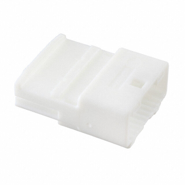
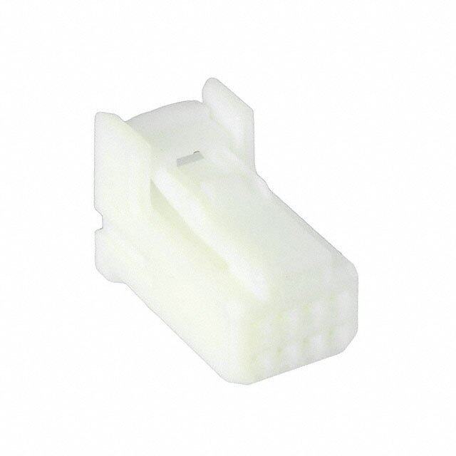
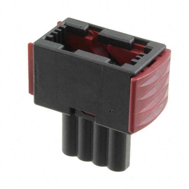
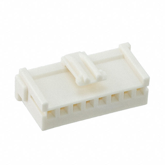
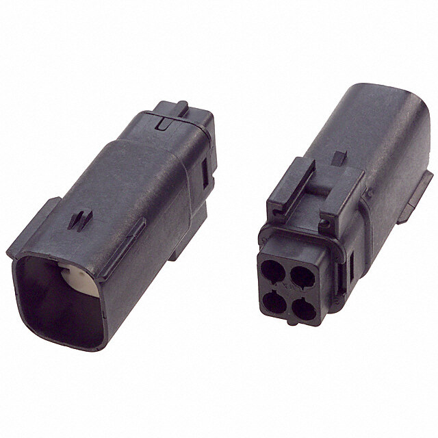
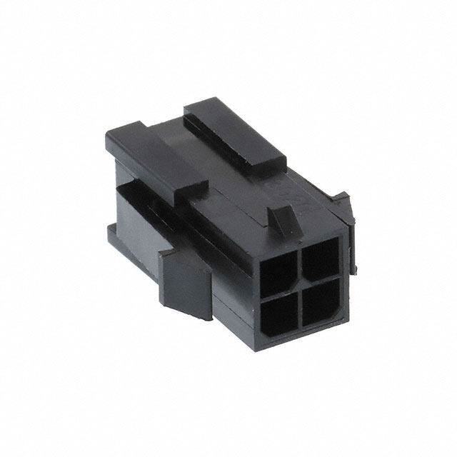
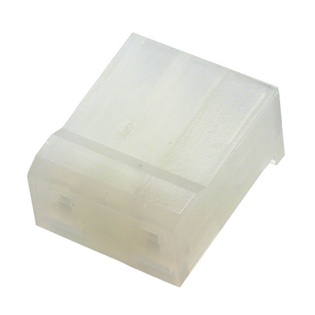
ICGOO电子元器件商城为您提供641685-1由CORCOM/TYCO ELECTRONICS设计生产,在icgoo商城现货销售,并且可以通过原厂、代理商等渠道进行代购。 641685-1价格参考¥36.77-¥36.77。CORCOM/TYCO ELECTRONICS641685-1封装/规格:矩形连接器 - 外壳, 4 针位 矩形外壳连接器 插头 。您可以下载641685-1参考资料、Datasheet数据手册功能说明书,资料中有641685-1 详细功能的应用电路图电压和使用方法及教程。
| 参数 | 数值 |
| 3D型号 | http://www.te.com/commerce/DocumentDelivery/DDEController?Action=srchrtrv&DocNm=641685-1&DocType=Customer+View+Model&DocLang=English |
| 产品目录 | |
| 描述 | PLUG,HIGH CURRENT,4 CIRCUITJones 插头和插槽 PLUG HIGH CURRENT 4 CIRCUIT |
| 产品分类 | |
| 品牌 | TE Connectivity / AMP |
| 产品手册 | http://www.te.com/catalog/pn/en/641685-1?RQPN=641685-1 |
| 产品图片 | |
| rohs | 符合RoHS无铅 / 符合限制有害物质指令(RoHS)规范要求 |
| 产品系列 | Jones 插头和插槽,TE Connectivity / AMP 641685-1- |
| 数据手册 | http://www.te.com/commerce/DocumentDelivery/DDEController?Action=srchrtrv&DocNm=641685&DocType=Customer+Drawing&DocLang=English |
| 产品型号 | 641685-1 |
| RoHS指令信息 | http://www.te.com/commerce/alt/SinglePartSearch.do?PN=641685-1&dest=stmt点击此处下载产品Datasheet |
| 产品种类 | Jones 插头和插槽 |
| 产品类型 | Connectors |
| 位置数量 | 4 |
| 其它名称 | 641685-1-ND |
| 包装 | 散装 |
| 商标 | TE Connectivity / AMP |
| 备注 | 不提供触点 |
| 外壳材料 | Nylon |
| 安装类型 | 面板安装,卡入式 |
| 工厂包装数量 | 1 |
| 排数 | 2 |
| 排距 | - |
| 标准包装 | 1 |
| 特性 | - |
| 相关产品 | /product-detail/zh/350650-1/A104013CT-ND/2816410/product-detail/zh/350651-1/A111157TR-ND/293001/product-detail/zh/350650-1/A104013TR-ND/293000 |
| 紧固类型 | - |
| 触头端接 | 压接 |
| 触头类型 | 公母通用 |
| 连接器类型 | 插头 |
| 配套产品 | /product-detail/zh/643267-1/A114187-ND/297686 |
| 针脚数 | 4 |
| 间距 | - |
| 颜色 | 红 |

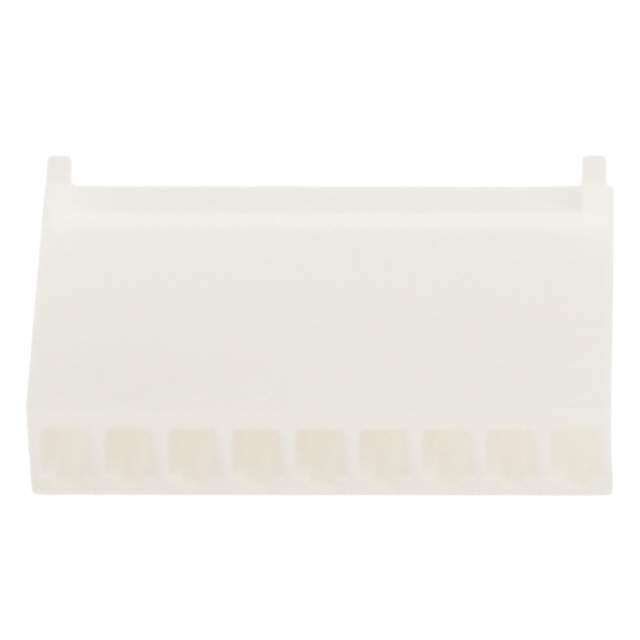
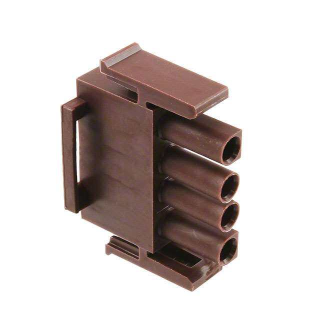
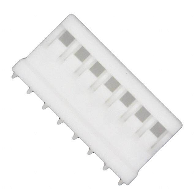

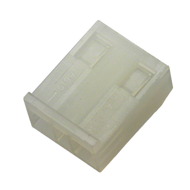

- 商务部:美国ITC正式对集成电路等产品启动337调查
- 曝三星4nm工艺存在良率问题 高通将骁龙8 Gen1或转产台积电
- 太阳诱电将投资9.5亿元在常州建新厂生产MLCC 预计2023年完工
- 英特尔发布欧洲新工厂建设计划 深化IDM 2.0 战略
- 台积电先进制程称霸业界 有大客户加持明年业绩稳了
- 达到5530亿美元!SIA预计今年全球半导体销售额将创下新高
- 英特尔拟将自动驾驶子公司Mobileye上市 估值或超500亿美元
- 三星加码芯片和SET,合并消费电子和移动部门,撤换高东真等 CEO
- 三星电子宣布重大人事变动 还合并消费电子和移动部门
- 海关总署:前11个月进口集成电路产品价值2.52万亿元 增长14.8%
PDF Datasheet 数据手册内容提取
METRIC Catalogue 1654742 Rast 5 Dimensions are Revised 5-04 millimetres over inches Table of Contents AMP multifitting Mark II Introduction ……………………………………………………………………………2002 Direct and Indirect Connection 5.0mm Centerline…………………………………2003 Derating Curves ………………………………………………………………………2004 Keying Plan and Cable Exit …………………………………………………………2005 Technical Features……………………………………………………………………2006 2 Direct Mating Connector System ……………………………………………2007, 2008 Indirect Mating Connector System……………………………………………2009-2011 PC Board Frame………………………………………………………………………2012 R AMP MONO-SHAPE a s Introduction ……………………………………………………………………………2013 t 5 Connector Versions …………………………………………………………………2014 Tab Connectors ………………………………………………………………………2015 Tab Connectors Keying Plan ………………………………………………………2016 Tab Connector 3-10 Positions ………………………………………………2017-2020 Single Way Connectors………………………………………………………………2021 Single Way Connectors Keying Plan ………………………………………………2022 PCB Connectors ………………………………………………………………2023-2027 Satellite Connectors …………………………………………………………………2028 Satellite Connectors Keying Plan……………………………………………………2029 Bridge Connectors Keying Plan ……………………………………………………2030 AMP MONO-SHAPE Mark II Introduction ……………………………………………………………………………2031 Technical Data ………………………………………………………………………2032 Keying Plan and Cable Exit …………………………………………………………2033 Tab Connector System ………………………………………………………2034-2035 TAB-BRIDGE Connector System - Short Circuit …………………………………2036 PCBConnector System ………………………………………………………2037-2041 Application Tooling ……………………………………………………………2042-2045 Standard Timer Introduction……………………………………………………………………………2046 Interior and Exterior Locking…………………………………………………………2047 Keying Plan……………………………………………………………………………2048 Housings ………………………………………………………………………2049-2059 Connectors and Contacts ……………………………………………………………2060 2001 Products for Industrial & Dimensions are shown for Dimensions are in inches and Specifications subject to www.tycoelectronics.com Commercial Applications reference purposes only. millimetres unless otherwise change. specified. Values in brackets are metric equivalents.
AMP multifitting Mark II METRIC Catalogue 1654742 Connectors in In-Line Mating Technology Dimensions are Revised 5-04 millimetres over inches Introduction Product Features (cid:2) Direct Mating Connectors for PC Boards,2–8 Positions, up to 6 A Current Carrying Capacity (cid:2) Indirect Mating Connectors, 1–8 Positions, up to 16 A Current Carrying Capacity (cid:2) Variable Keying (cid:2) Double Wire Termination possible Tyco Electronics’ newly This system is suitable for a Interior locking options are designed AMP multifitting wide wire size range. available on request. Mark II Connector System Current carrying capacity is Supplied in chain and was developed according 16 A maximum. provided with all keying and to the latest connector Double termination is polarisation ribs,the design standards. possible with 0.5 and 0.5 connectors can be operated The requirements of mm2or 0.5 and 0.75 mm2 economically with modern advanced In-Line mating conductors. Application Tooling technology for the Equipment. The connectors are avail- components and contacts of able in 1-to 8-positions pc boards are incorporated (indirect) resp.2-to 8- in the direct and indirect positions (direct) with an versions of these connector exterior locking device. systems. 2002 Products for Industrial & Dimensions are shown for Dimensions are in inches and Specifications subject to www.tycoelectronics.com Commercial Applications reference purposes only. millimetres unless otherwise change. Conversion Rate: specified. Values in brackets 25.4mm = 1 inch are metric equivalents.
AMP multifitting Mark II METRIC Catalogue 1654742 Connectors in In-Line Mating Technology Dimensions are Revised 5-04 millimetres over inches Direct and Indirect Mating Connection, 5.0 mm Centerline Direct Mating Connection, 5.0 mm Centerline 3 4 1 Double Wire Exit 2 Wire Exit 90° 2 3 Wire Exit 180° 4 Cover R a s 5 Exterior Locking Latch t 5 5 6 Keying 1 7 Polarisation 2 6 7 Indirect Mating Connection, 5.0 mm Centerline 3 4 1 Double Wire Exit 2 Wire Exit 90° 3 Wire Exit 180° 4 Cover 5 Exterior Locking Latch 5 6 Keying 1 7 Polarisation 2 6 7 Indirect Mating Connection with Interior Locking, 3 4 5.0 mm Centerline 1 Double Wire Exit 2 Wire Exit 90° 3 Wire Exit 180° 4 Cover 5 Interior Locking Latch 1 6 Keying 7 Polarisation 2 7 5 6 2003 Products for Industrial & Dimensions are shown for Dimensions are in inches and Specifications subject to www.tycoelectronics.com Commercial Applications reference purposes only. millimetres unless otherwise change. Conversion Rate: specified. Values in brackets 25.4mm = 1 inch are metric equivalents.
AMP multifitting Mark II METRIC Catalogue 1654742 Connectors in In-Line Mating Technology Dimensions are Revised 5-04 millimetres over inches Derating Curves Direct Mating Connector System I/A 7 6 Connector: 5 8 positions Material: ent 4 Brass, tin plated urr 3 C Wire: 2 0.5 mm2 1 PCBoard: 0 t/°C FR4, 2 x 0.35 µm Copper, 0 10 20 30 40 50 60 70 80 90 100 110 tin plated Ambient Temperature Indirect Mating Connector I///AA 3 System 10 9 Material: 8 Curve 1: Brass, tin plated 7 2 positions Wire: 6 2 1 Curve 2: 0.5 mm2(Curve 1 and 2) nt 8 positions e 1.0 mm2(Curve 3) urr 5 Curve 3: C 4 positions Mating Part: 4 6.3 x 0.8 mm Tab, 3 Brass, tin plated 2 1 0 t///ϒϒϒϒCC 0 20 40 60 80 100 120 Ambient Temperature Indirect Mating Connector I/A System 18 2 1 16 Curve 1: 1position Material: 14 Curve 2: CuNi2Si, silver plated 12 4 positions Wire: nt 10 e 1.5 mm2, tin plated Curr 8 Mating Part: 6.3 x 0.8 mm Tab, 6 Brass, tin plated 4 2 0 t/°C 0 20 40 60 80 100 120 140 Ambient Temperature 2004 Products for Industrial & Dimensions are shown for Dimensions are in inches and Specifications subject to www.tycoelectronics.com Commercial Applications reference purposes only. millimetres unless otherwise change. Conversion Rate: specified. Values in brackets 25.4mm = 1 inch are metric equivalents.
AMP multifitting Mark II METRIC Catalogue 1654742 Connectors in In-Line Mating Technology Dimensions are Revised 5-04 millimetres over inches Keying Plan and Cable Exit Keying Plan 4 3 from Mating Direction, Fully-Keyed Version a b – – – – – 1 Locking Latch 1 2 3 4 5 2 2 Keying Rib – – – – – 3 Polarisation Rib c d 4 Cavity Number R a s 1 2 t 5 Keyed Version: 05-C according RAST 5 b – – – – – This final keying version will be 1 2 3 4 5 produced on the Application – – – – – Tooling Equipment. d c Cable Exit with Interior and Exterior Locking Cable Exit with Interior Locking Cable Exit with Exterior Locking Direct Mating of a PCB with PC Board Frames 2005 Products for Industrial & Dimensions are shown for Dimensions are in inches and Specifications subject to www.tycoelectronics.com Commercial Applications reference purposes only. millimetres unless otherwise change. Conversion Rate: specified. Values in brackets 25.4mm = 1 inch are metric equivalents.
AMP multifitting Mark II METRIC Catalogue 1654742 Connectors in In-Line Mating Technology Dimensions are Revised 5-04 millimetres over inches Technical Features Technical Data Centerline: 5.0 mm Housing Material: Polyamide, PA 6.6 and PA 6 Standard Colour: Natural Current Voltage: 250 V ~ Air and Creepage Distance: >3.2 mm Flammability Rating: UL 94 V-2 Approvals: VDE, UL Direct Mating Connectors Indirect Mating Connectors No. of Positions: No. of Positions: 2- to 8-positions 1- to 8-positions Contact Material: Contact Material: Brass Brass/CuNi2Si Contact Finish: Contact Finish: Tin plated Tin plated/silver plated Wire Size Range: Wire Size Range: 0.35–1.0 mm2 0.35–1.0 mm2/1.0–1.5 mm2 Temperature Range: Temperature Range: –40 °C up to +105 °C –40 °C up to +130 °C Current Rating: Current Rating: 6 A max. 10 A, up to 4 contacts 16 A Insulation Diameter: Insulation Diameter: 2.8 mm max. 3.0 mm max. Insulation Resistance: Insulation Resistance: >10 MΩ >10 MΩ Mating Force: Mating Force: ≤7 N per contact* ≤6.5 N per contact** Unmating Force: Unmating Force: ≥1.5 N* ≥1.5 N** Product Specification: Product Specification: 108-18653 108-18652 Application Specification: Application Specification: 114-18289 114-18288, 114-18382 *)measured with polished steel **)measured with polished steel plate 1.5 mm thickness tab 6.3 x 0.8 mm 2006 Products for Industrial & Dimensions are shown for Dimensions are in inches and Specifications subject to www.tycoelectronics.com Commercial Applications reference purposes only. millimetres unless otherwise change. Conversion Rate: specified. Values in brackets 25.4mm = 1 inch are metric equivalents.
AMP multifitting Mark II METRIC Catalogue 1654742 Connectors in In-Line Mating Technology Dimensions are Revised 5-04 millimetres over inches Direct Mating Connector System Technical Data Wire Size Range: 0.35–1.0 mm2 Current Carrying Capacity (max.): 6 A 2 Part Numbers Part Numbers with Exterior Locking Package with Interior Locking RAST 5 Version Quantity PA 6.6 PA 6* PA 6.6 PA 6* R a s – – t 5 1 2 1-1241172-2 1-1534075-2 4,900 – – – – – – – 1 2 3 1-1241172-3 1-1534075-3 3,136 – – – – – – – – 1 2 3 1-1241172-3 1-1534075-3 3,136 – – – – – – – – – 1 2 3 4 1-1241172-4 1-1534075-4 2,352 – – – – – – – – – – 1 2 3 4 1-1241172-4 1-1534075-4 2,352 – – – – – – – – – – – 1 2 3 4 5 1-1241172-5 1-1534075-5 1,960 – – – – – – – – – – – – 1 2 3 4 5 1-1241172-5 1-1534075-5 1,960 – – – – – – – *)According to IEC 60695-2-1/1; GWT (Glow Wire Test) 750 °C without flame, see VDE M-Test Report. The final keying version will be produced on the Application Tooling Equipment. 2007 Products for Industrial & Dimensions are shown for Dimensions are in inches and Specifications subject to www.tycoelectronics.com Commercial Applications reference purposes only. millimetres unless otherwise change. Conversion Rate: specified. Values in brackets 25.4mm = 1 inch are metric equivalents.
AMP multifitting Mark II METRIC Catalogue 1654742 Connectors in In-Line Mating Technology Dimensions are Revised 5-04 millimetres over inches Direct Mating Connector System (continued) Technical Data Wire Size Range: 0.35–1.0 mm2 Current Carrying Capacity (max.): 6 A Part Numbers Part Numbers with Exterior Locking Package with Interior Locking RAST 5 Version Quantity PA 6.6 PA 6* PA 6.6 PA 6* – – – – – – 1 2 3 4 5 6 1-1241172-6 1-1534075-6 1,568 – – – – – – – – – – – – – – 1 2 3 4 5 6 1-1241172-6 1-1534075-6 1,568 – – – – – – – – – – – – – – 1 2 3 4 5 6 2-1241172-6 2-1534075-6 1,568 – – – – – – – – – – – – – – – 1 2 3 4 5 6 7 1-1241172-7 1-1534075-7 1,372 – – – – – – – – – – – – – – – – 1 2 3 4 5 6 7 1-1241172-7 1-1534075-7 1,372 – – – – – – – – – – – – – – – – – 1 2 3 4 5 6 7 8 1-1241172-8 1-1534075-8 1,176 – – – – – – – – – – – – – – – – – – 1 2 3 4 5 6 7 8 1-1241172-8 1-1534075-8 1,176 – – – – – – – – – – *)According to IEC 60695-2-1/1; GWT (Glow Wire Test) 750 °C without flame, see VDE M-Test Report. The final keying version will be produced on the Application Tooling Equipment. 2008 Products for Industrial & Dimensions are shown for Dimensions are in inches and Specifications subject to www.tycoelectronics.com Commercial Applications reference purposes only. millimetres unless otherwise change. Conversion Rate: specified. Values in brackets 25.4mm = 1 inch are metric equivalents.
AMP multifitting Mark II METRIC Catalogue 1654742 Connectors in In-Line Mating Technology Dimensions are Revised 5-04 millimetres over inches Indirect Mating Connector System Technical Data Wire Size Range: Current Carrying Capacity 0.35–1.0 mm2 (max.): 10 A Part Numbers Part Numbers with Exterior Locking Package with Interior Locking RAST 5 Version Quantity 2 PA 6.6 PA 6* PA 6.6 PA 6* – R 1 1-1241170-1 1-1534072-1 9,604 -1241170-1 1-1534072-1 a s – t 5 – – 1 2 1-1241170-2 1-1534072-2 4,900 1-1394355-2 1-1534077-2 – – – – – 1 2 3 1-1241170-3 1-1534072-3 3,136 1-1394355-3 1-1534077-3 – – – – – – 1 2 3 1-1241170-3 1-1534072-3 3,136 1-1394355-3 1-1534077-3 – – – – – – – 1 2 3 4 1-1241170-4 1-1534072-4 2,352 1-1394355-4 1-1534077-4 – – – – – – – – 1 2 3 4 1-1241170-4 1-1534072-4 2,352 1-1394355-4 1-1534077-4 – – – – – – – – – 1 2 3 4 5 1-1241170-5 1-1534072-5 1,960 1-1394355-5 1-1534077-5 – – – – – – – – – – 1 2 3 4 5 1-1241170-5 1-1534072-5 1,960 1-1394355-5 1-1534077-5 – – – – – *)According to IEC 60695-2-1/1; GWT (Glow Wire Test) 750 °C without flame, see VDE M-Test Report. The final keying version will be produced on the Application Tooling Equipment. 2009 Products for Industrial & Dimensions are shown for Dimensions are in inches and Specifications subject to www.tycoelectronics.com Commercial Applications reference purposes only. millimetres unless otherwise change. Conversion Rate: specified. Values in brackets 25.4mm = 1 inch are metric equivalents.
AMP multifitting Mark II METRIC Catalogue 1654742 Connectors in In-Line Mating Technology Dimensions are Revised 5-04 millimetres over inches Indirect Mating Connector System (continued) Technical Data Wire Size Range: Current Carrying Capacity 0.35–1.0 mm2 (max.): 10 A Part Numbers Part Numbers with Exterior Locking Package with Interior Locking RAST 5 Version Quantity PA 6.6 PA 6* PA 6.6 PA 6* – – – – – – 1 2 3 4 5 6 1-1241170-6 1-1534072-6 1,568 – – – – – – – – – – – – – – 1 2 3 4 5 6 1-1241170-6 1-1534072-6 1,568 – – – – – – – – – – – – – – 1 2 3 4 5 6 2-1241170-6 2-1534072-6 1,568 – – – – – – – – – – – – – – – 1 2 3 4 5 6 7 1-1241170-7 1-1534072-7 1,372 – – – – – – – – – – – – – – – – 1 2 3 4 5 6 7 1-1241170-7 1-1534072-7 1,372 1394355-7 1534077-7 – – – – – – – – – – – – – – – 1 2 3 4 5 6 7 8 1-1241170-8 1-1534072-8 1,176 – – – – – – – – – – – – – – – – – – 1 2 3 4 5 6 7 8 1-1241170-8 1-1534072-8 1,176 – – – – – – – – – – *)According to IEC 60695-2-1/1; GWT (Glow Wire Test) 750 °C without flame, see VDE M-Test Report. The final keying version will be produced on the Application Tooling Equipment. 2010 Products for Industrial & Dimensions are shown for Dimensions are in inches and Specifications subject to www.tycoelectronics.com Commercial Applications reference purposes only. millimetres unless otherwise change. Conversion Rate: specified. Values in brackets 25.4mm = 1 inch are metric equivalents.
AMP multifitting Mark II METRIC Catalogue 1654742 Connectors in In-Line Mating Technology Dimensions are Revised 5-04 millimetres over inches Indirect Mating Connector System (continued) Technical Data Wire Size Range: 1.0–1.5 mm2 Current Carrying Capacity (max.): 16 A 2 Part Numbers Part Numbers with Exterior Locking Package with Interior Locking RAST 5 Version Quantity PA 6.6 PA 6* PA 6.6 PA 6* R a s – t 5 1 1-1241171-1 1-1534073-1 9,604 1--1241171-1 1-1534073-1 – – – 1 2 1-1241171-2 1-1534073-2 4,900 1-1394556-2 1-1534078-2 – – – – – 1 2 3 1-1241171-3 1-1534073-3 3,136 1-1394556-3 1-1534078-3 – – – – – – 1 2 3 1-1241171-3 1-1534073-3 3,136 1-1394556-3 1-1534078-3 – – – – – – – 1 2 3 4 1-1241171-4 1-1534073-4 2,352 1-1394556-4 1-1534078-4 – – – – – – – – 1 2 3 4 1-1241171-4 1-1534073-4 2,352 1-1394556-4 1-1534078-4 – – – – *)According to IEC 60695-2-1/1; GWT (Glow Wire Test) 750 °C without flame, see VDE M-Test Report. The final keying version will be produced on the Application Tooling Equipment. 2011 Products for Industrial & Dimensions are shown for Dimensions are in inches and Specifications subject to www.tycoelectronics.com Commercial Applications reference purposes only. millimetres unless otherwise change. Conversion Rate: specified. Values in brackets 25.4mm = 1 inch are metric equivalents.
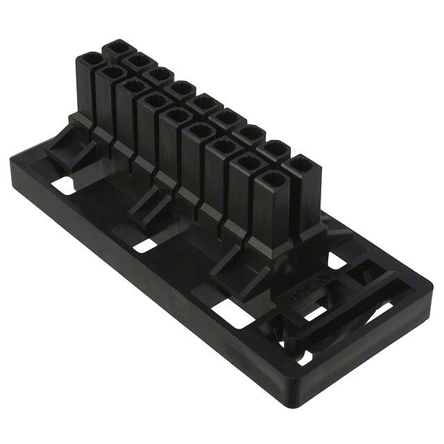
AMP multifitting Mark II METRIC Catalogue 1654742 Connectors in In-Line Mating Technology Dimensions are Revised 5-04 millimetres over inches PC Board Frame Latching Hole Keying PCBoard Frame PCBoard B A Dimensions Part Number Additional No. of (mm) Package Keying Latching Polarisation Board Positions PCBoard Frame, Quantity Lock A B PA 6.6, Black 2 5 10.1 1c, 2d 1/2 – – 2-964577-2 2,200 1c, 2d, 3c 1/2, 3/4 2b – 1-964577-4 4 15 20.1 1c, 3c, 4d 1/2, 3/4 4b – 2-964577-4 1,700 1c, 3c, 4d 1/2, 3/4 1b, 4a – 3-964577-4 5 20 25.1 3d 1/2, 4/5 – – 1-964577-5 1,500 4d 1/2, 5/6 6b – 1-964577-6 6 25 30.1 1,500 4d 1/2, 5/6 1b, 6a – 2-964577-6 2c, 3d, 7c 2/3, 5/6 1b, 2b 4/5 1-964577-7 7 30 35.1 1,200 2c, 3d, 7c 2/3, 5/6 2b, 7a 4/5 2-964577-7 2c, 3d, 7c 2/3, 7/8 2a 4/5 1-964577-8 8 35 40.1 1,000 2c, 3d, 7c 2/3, 7/8 2b, 4b 4/5 2-964577-8 1c, 2d, 3c, 4d, 1/2, 3/4, 5/6, 2b, 3a, 4a, 6a, 122 55 60.1 5c, 8c, 10d, 12d 8/9, 9/10, 11/12 7a, 7b, 8a, 8b 4/5, 8/9 1-964578-2 1.500 Preferred Parts are printed bold 2012 Products for Industrial & Dimensions are shown for Dimensions are in inches and Specifications subject to www.tycoelectronics.com Commercial Applications reference purposes only. millimetres unless otherwise change. Conversion Rate: specified. Values in brackets 25.4mm = 1 inch are metric equivalents.
AMP MONO-SHAPE METRIC Catalogue 1654742 Connectors in In-Line Mating Technology Dimensions are Revised 5-04 millimetres over inches Introduction AMP MONO-SHAPE Connectors in In-Line Mating Technology AMP MONO-SHAPE connectors represent a valid solution to the 2 ever-increasing requirements for production and application flexibility.They are high productivity,great flexibility, R a quality, minimum applied cost. s t 5 AMP MONO-SHAPE product- line includes a full range of 5.0 mm pitch modular connectors contents with similar outer shape, several variation in the mating area such as PC Board and 6.3 x 0.8 mm tabs (RAST 5), plus a version for harness shunts. AMP MONO-SHAPE connection system adopts the IDC termination technology,which improves application results and quality level. The AMP MONO-SHAPE product range,combined with the performances and properties offered by the Technical Features termination system,allow to manufacture extremely (cid:2) IDC Connector system (cid:2) The connector incorporates complicated harness structures design to maximise the modern in-line mating while still maintaining high full integration with the technology on a 5.0 mm production levels. application tooling assuring centerline with no loss of total flexibility in harness spacing and a variety of design. keying possibilities. (cid:2) High current system, up (cid:2) Wiring faults eliminated to16 Ampere, designed to through high automation. satisfy several appliance (cid:2) Approvals: requirements. VDE: 4751-1431-4024 / A (cid:2) ID Contact designed to 10A and accept standard discrete 4751-1431-4024 / A 9E wires ranging from 0.5 up to UL E 28476 Vol. 9 Sec. 7; 1.5 mm2,according to the 97 ME 17936; AP-27HB connector configuration. 2013 Products for Industrial & Dimensions are shown for Dimensions are in inches and Specifications subject to www.tycoelectronics.com Commercial Applications reference purposes only. millimetres unless otherwise change. Conversion Rate: specified. Values in brackets 25.4mm = 1 inch are metric equivalents.
AMP MONO-SHAPE METRIC Catalogue 1654742 Connectors in In-Line Mating Technology Dimensions are Revised 5-04 millimetres over inches AMP MONO-SHAPE Connector Versions Same Shape - Different Applications With the same outside shape four connector versions are available, which are to handle with the same application tooling. TAB Connectors 2–12 position 5.0 mm pitch Wire Size Range: connectors with insulation 0.5–1.5 mm2 displacement contacts mateable Current Rating: with components according to 16 Ampere max. acc. to wire size LIF version 2 RAST 5 and with tinned copper point contact alloy tab 6.3 x 0.8 mm -For LIF version up to instead of 4 as according to DIN 46244. 10 Ampere max per standard version Single Way Connectors Single Way connectors with Wire Size Range: insulation displacement 0.5–1.5 mm2 contacts for use on tinned Current Rating: copper alloy tab 6.3 x 0.8 mm 16 Ampere max. acc. to wire size according to DIN 46244. Supply Status: In order to increase product- ivity these items are supplied in sticks. PCB Connectors 2–12 position 5.0 mm pitch Wire Size Range: connectors with insulation 0.5–0.75 mm2 displacement contacts accor- Current Rating: ding to printed circuit boards 6 Ampere max. acc. to wire size with thickness 1.5±0.2mm and PC Board: 5.0 mm pitch. Single or both sides printed 5 µm tin over 35 µm copper Satellite Connectors 3 position connectors, pitch Wire Size Range: 5.0 mm, with short circuited 0.5–1.5 mm2 insulation displacement Current Rating: contacts for harness shunts. 16 Ampère max. acc. to wire size 2014 Products for Industrial & Dimensions are shown for Dimensions are in inches and Specifications subject to www.tycoelectronics.com Commercial Applications reference purposes only. millimetres unless otherwise change. Conversion Rate: specified. Values in brackets 25.4mm = 1 inch are metric equivalents.
AMP MONO-SHAPE METRIC Catalogue 1654742 Connectors in In-Line Mating Technology Dimensions are Revised 5-04 millimetres over inches TAB Connector AMP MONO-SHAPE TAB Connector 1 6 1 Cover closed after Wire Insertion. Wire Direction 2 90°. 180°when locked in Cover Recess 2 Cavity Numbers 2 R 3 Polarisation a s similar to the Keying t 5 (Located on the Back Side) 3 4 Keying 5 Interior Locking Latch 5 6 Colour Marking 4 Technical Features Centerline: Voltage Resistance: or FR 3/2(105 °C max.) 5.0 mm, according to RAST 5 according to EN 60998-1 for wires from1.5 mm2with specifications (IEC 998-1) 1750 V for 4 minutes copper or tinned stranded wires Configurations: Insulation Resistance: Insulation Type: 2- to 12-positions according to EN 60998-1 PVC suitable for temperatures Housing Material: (IEC 998-1) >5 MΩ up to 70 °C / 105 °C Plastic PA 6.6 Wire Size Range: Insulation Diameter Range: Housing Colour: from 0.5 to1.5 mm2 2.0–3.5 mm Natural colour for standard Current Rating: Temperature Range: version Standard Version –25 °C up to +105 °C Grey colour for LIF version 16 A max. according to wire Wire Extraction Force/Way: Contact Material: size 50 N min. on wire size 0.5 mm2 Copper alloy, post-tinned 0.5 mm2≤3 A, 0.75 mm2≤6 A, Application Specification: 2.0 µm min. 1.0 mm2≤10 A, 1.5 mm2≤16 A 114-20016 Polarisation, Keying, LIF Version Product Specification: Locking Latches: 10 A max. according to wire Standard version: 108-20065 according to RAST 5 size LIF version: 108-20215 s(speeec icfiucsattoiomnesr drawings) 01..05 mmmm22≤≤31 0A A, 0, .17.55 mmmm22≤≤160 A A, Hacocm.too lVoDgaEt iFoilnes N: o. 3905 Track Resistance: Rated Voltage: (to 16 A) and UL File No. as per IEC 112 (250 V) 380 Volts max. E28476 (to 14 A) Glow Wire Test: Wire Type: as per IEC 695-2-1 (850 °C) H05V-K(70 °C max.) and 750°C no flame or FR 3/2(105 °C max.) for 0.5–1.0 mm2wires with Air and Creepage Distance: copper or tinned stranded wires according to EN 60998-1 (IEC 998-1) for 380 V, ≥4.0 mm H07V-K(70 °C max.) 2015 Products for Industrial & Dimensions are shown for Dimensions are in inches and Specifications subject to www.tycoelectronics.com Commercial Applications reference purposes only. millimetres unless otherwise change. Conversion Rate: specified. Values in brackets 25.4mm = 1 inch are metric equivalents.
AMP MONO-SHAPE METRIC Catalogue 1654742 Connectors in In-Line Mating Technology Dimensions are Revised 5-04 millimetres over inches Keying Plan Keying Plan 5 4 from Mating Direction, 1 Locking Latch 2 Slanted Keying Rib a b 3 Keying Rib – – – – – – – 1 2 3 4 5 6 7 4 Polarisation Rib – – – – – – – 5 Cavity Number c d c AMP MONO-SHAPE 1 2 3 TAB Connector 2 Position RAST 5 Variations (Variable Keying)* Part Packaging Suitable for RAST 5 Version Numbers Unit RAST 5 Version Colour Marking On Tray Loose Piece On Reel On Reel Loose Piece On Reel 02-B 02-E a– –b 1-282002-2 2-282002-2 3-282002-2 02-F 1 2 6.500 3.500 28.500 – – 1-284338-2 2-284338-2 — Grey c d 02-C – a– 1-282002-1 2-282002-1 2-282002-1 1 2 6.500 3.500 28.500 Black – – 1-284338-1 2-284338-1 — c d 02-L b 02-P 1 – 2 – 1-282002-3 2-282002-3 — 6.500 3.500 28.500 Red – – 1-284338-3 2-284338-3 3-284338-3 c d 02-A 02-O 1-282002-4 2-282002-4 — 6.500 3.500 — 1-284338-4 — — Blue 02-Q 1-282002-5 2-282002-5 — 6.500 3.500 — Black — 1-282002-6 2-282002-6 — 6.500 3.500 — Black — 1-282002-7 2-282002-7 3-282002-7 6.500 3.500 28.500 — 1-284338-7 — — * Final keying version is produced on the Application Tooling Machines. Bold Part Numbers are LIF Version 2016 Products for Industrial & Dimensions are shown for Dimensions are in inches and Specifications subject to www.tycoelectronics.com Commercial Applications reference purposes only. millimetres unless otherwise change. Conversion Rate: specified. Values in brackets 25.4mm = 1 inch are metric equivalents.
AMP MONO-SHAPE METRIC Catalogue 1654742 Connectors in In-Line Mating Technology Dimensions are Revised 5-04 millimetres over inches AMP MONO-SHAPE TAB Connector 3 Position RAST 5 Variations (Variable Keying)* Part Packaging Suitable for RAST 5 Version Numbers Unit RAST 5 Version Colour Marking 2 On Tray Loose Piece On Reel On Reel Loose Piece On Reel 03-A b 03-I 1 – 2 – 3 – 1-282003-1 2-282003-1 3-282003-1 4.160 2.500 24.000 R Orange c– – dc– d 1-284339-1 2-284339-1 — ast 5 03-B b b 03-K 1 – 2 – 3 – 1-282003-2 2-282003-2 3-282003-2 4.160 2.500 24.000 – – – 1-284339-2 2-284339-2 — Blue c dc d a b 03-F – – – 1-282003-3 2-282003-3 — 1 2 3 4.160 2.500 — Green – – – 1-284339-3 2-284339-3 — c dc d a 03-D – – – 1 2 3 282233-2 282233-2 — 4.160 2.500 — – – – – c c d 03-B b b 03-K 1 – 2 – 3 – 1-282003-4 2-282003-4 — 4.160 2.500 — – – – 1-284339-4 2-284339-4 — Red c dc d 03-B b b 03-K 1 – 2 – 3 – 1-282003-5 2-282003-5 — 4.160 2.500 — – – – 1-284339-5 2-284339-5 — Grey c dc d — 1-282003-6 2-282003-6 — 4.160 2.500 — Violet b b 03-B – – – 1 2 3 1-282003-7 — — 4.160 — — Black – – – c dc d — 1-284396-1 — — 4.160 — — Black * Final keying version is produced on the Application Tooling Machines. Bold Part Numbers are LIF Version 2017 Products for Industrial & Dimensions are shown for Dimensions are in inches and Specifications subject to www.tycoelectronics.com Commercial Applications reference purposes only. millimetres unless otherwise change. Conversion Rate: specified. Values in brackets 25.4mm = 1 inch are metric equivalents.
AMP MONO-SHAPE METRIC Catalogue 1654742 Connectors in In-Line Mating Technology Dimensions are Revised 5-04 millimetres over inches AMP MONO-SHAPE TAB Connector 4 Position RAST 5 Variations (Variable Keying)* Part Packaging Suitable for RAST 5 Version Numbers Unit RAST 5 Version Colour Marking On Tray Loose Piece On Reel On Reel Loose Piece On Reel 04-A –b – – – 1 2 3 4 1-282004-1 2-282004-1 3-282004-1 2.120 2.000 18.750 Grey – – – – c dc d 04-D – – –b – 1 2 3 4 1-282004-2 2-282004-2 3-282004-2 2.120 2.000 18.750 Black – – – – c dc dc d 04-A –b – – – 1 2 3 4 1-282004-3 2-282004-3 — 2.120 2.000 — Red – – – – c dc d 5 Position RAST 5 Variations (Variable Keying)* Part Packaging Suitable for RAST 5 Version Numbers Unit RAST 5 Version Colour Marking On Tray Loose Piece On Reel On Reel Loose Piece On Reel b – – – – – Red 1 2 3 4 5 1-282005-1 2-282005-1 — 2.600 1.500 18.750 – – – – – c dc dc dc d Red 1-284545-1 — — 2.600 1.500 18.750 * Final keying version is produced on the Application Tooling Machines. 2018 Products for Industrial & Dimensions are shown for Dimensions are in inches and Specifications subject to www.tycoelectronics.com Commercial Applications reference purposes only. millimetres unless otherwise change. Conversion Rate: specified. Values in brackets 25.4mm = 1 inch are metric equivalents.
AMP MONO-SHAPE METRIC Catalogue 1654742 Connectors in In-Line Mating Technology Dimensions are Revised 5-04 millimetres over inches AMP MONO-SHAPE TAB Connector 6 Position RAST 5 Variations (Variable Keying)* Part Packaging Suitable for RAST 5 Version Numbers Unit RAST 5 Version Colour Marking 2 On Tray Loose Piece On Reel On Reel Loose Piece On Reel Violet 1-282006-1 2-282006-2 3-282006-2 2.080 1.200 13.500 R a s t 5 — 1-282006-3 2-282006-3 3-282006-3 2.080 1.200 13.500 Red 1-284745-1 — — 2.080 — — 7 Position RAST 5 Variations (Variable Keying)* Part Packaging Suitable for RAST 5 Version Numbers Unit RAST 5 Version Colour Marking On Tray Loose Piece On Reel On Reel Loose Piece On Reel b b – – – – – – – — 1 2 3 4 5 6 7 1-282007-1 2-282007-1 — 1.820 1.200 — – – – – – – – c dc dc dc dc d Black 1-284397-1 — — 1.820 1.200 — 2019 Products for Industrial & Dimensions are shown for Dimensions are in inches and Specifications subject to www.tycoelectronics.com Commercial Applications reference purposes only. millimetres unless otherwise change. Conversion Rate: specified. Values in brackets 25.4mm = 1 inch are metric equivalents.
AMP MONO-SHAPE METRIC Catalogue 1654742 Connectors in In-Line Mating Technology Dimensions are Revised 5-04 millimetres over inches AMP MONO-SHAPE TAB Connector 8 Position RAST 5 Variations (Variable Keying)* Part Packaging Suitable for RAST 5 Version Numbers Unit RAST 5 Version Colour Marking On Tray Loose Piece On Reel On Reel Loose Piece On Reel – –b – –b – a–b – – 284085-1 2-284085-1 — — 1 2 3 4 5 6 7 8 1.560 900 — – – – – – – – – 1-284685-1 2-284685-1 — c dc dc dc dc dc dc dc d Violet 284085-2 2-284085-2 — 1.560 900 — * Final keying version is produced on the Application Tooling Machines. Bold Part Numbers are LIF Version 10 Position RAST 5 Variations (Variable Keying)* Part Packaging Suitable for RAST 5 Numbers Unit Version RAST 5 Version Colour Marking On Tray Loose Piece On Reel On Reel Loose Piece On Reel – – – – – –b –a– – – 1-282010-1 2-282010-1 — — – 1 – 2 – 3 – 4 – 5 – 6 – 7 – 8 – 9 –10 1-284686-1 2-284686-1 — 1.300 700 — c dc dc dc dc dc dc dc d * Final keying version is produced on the Application Tooling Machines. Bold Part Numbers are LIF Version 2020 Products for Industrial & Dimensions are shown for Dimensions are in inches and Specifications subject to www.tycoelectronics.com Commercial Applications reference purposes only. millimetres unless otherwise change. Conversion Rate: specified. Values in brackets 25.4mm = 1 inch are metric equivalents.
AMP MONO-SHAPE METRIC Catalogue 1654742 Connectors in In-Line Mating Technology Dimensions are Revised 5-04 millimetres over inches AMP MONO-SHAPE Single Way Connector Single Way Connector 1 2 1 All Single Way Connectors are supplied in “stick-form” by 6 single ways each. They will be cut from the 2 ApplicationTooling Machines 2 Cover closed after Wire Insertion. Wire Direction 90°. R 180°when locked in Cover a s Recess t 5 3 Polarisation similar to the keying of the front side 3 4 Keying 5 Plastic Noses which Lock into the TAB Hole 6 Colour Marking 5 4 Technical Features Centerline: Voltage Resistance: Insulation Type: 5.0 mm, according to RAST according to EN 60998-1 PVC suitable for temperatures 5 specifications (IEC 998-1) 1750 V for 4 up to 70 °C / 105 °C Configurations: minutes Insulation Diameter Range: 1 position Insulation Resistance: 2.0–3.5 mm Housing Material: according to EN 60998-1 Temperature Range: Plastic PA 6.6 (IEC 998-1) >5 MΩ –25 °C up to +105 °C Housing Colour: Wire Size Range: Wire Extraction Force/Way: Natural colour from 0.5 to1.5 mm2 50 N min. on wire size 0.5 mm2 Contact Material: Current Rating: Application Specification: Copper alloy, post-tinned 16 A max. according to wire 114-20017 2.0 µm min. s0i.z5e mm2≤3 A, 0.75 mm2≤6 A, Product Specification: Polarisation, Keying, 1.0 mm2≤10 A, 1.5 mm2≤16 A 108-20066 Locking Latches: Homologations: according to RAST 5 Rated Voltage: acc.to VDE File No. 3905 specifications 380 Volts max. (to 16 A) and UL File No. (see customer drawings) Wire Type: E28476 (to 14 A) Track Resistance: H05V-K(70 °C max.) Counter Part: as per IEC 112 (250 V) or FR 3/2(105 °C max.) Tab 6.3 x 0.8 mm for 0.5–1.0 mm2wires with Glow Wire Test: as per DIN 46244 norms copper or tinned stranded wires as per IEC 695-2-1 (850 °C) Materials: and 750°C no flame H07V-K(70 °C max.) Copper alloy or FR 3/2(105 °C max.) Air and Creepage Distance: for wires from1.5mm2with Finishing: according to EN 60998-1 copper or tinned stranded wires Tinned (6.0 µm max.) (IEC 998-1) for 380 V, ≥4.0 mm 2021 Products for Industrial & Dimensions are shown for Dimensions are in inches and Specifications subject to www.tycoelectronics.com Commercial Applications reference purposes only. millimetres unless otherwise change. Conversion Rate: specified. Values in brackets 25.4mm = 1 inch are metric equivalents.
AMP MONO-SHAPE METRIC Catalogue 1654742 Connectors in In-Line Mating Technology Dimensions are Revised 5-04 millimetres over inches Keying Plan from Mating Direction Keying Plan 2 1 Keying Rib 2 Polarisation Rib a 3 – 3 Cavity Number 1 – c d 1 AMP MONO-SHAPE Single Way Connector 1 Position (Variable Keying)* Part Packaging Suitable for RAST 5 Version Numbers Unit RAST 5 Version Colour Marking On Tray On Reel On Tray On Reel – — 1 — 1-282086-1 1.024 10.500 – c d a – Black 1 — 1-282086-2 1.024 — – c d b – Orange 1 — 1-282086-3 1.024 — – c d Green — 1-282086-4 1.024 — Blue — 1-282086-5 1.024 — Violet — 1-282086-6 1.024 — 2022 Products for Industrial & Dimensions are shown for Dimensions are in inches and Specifications subject to www.tycoelectronics.com Commercial Applications reference purposes only. millimetres unless otherwise change. Conversion Rate: specified. Values in brackets 25.4mm = 1 inch are metric equivalents.
AMP MONO-SHAPE METRIC Catalogue 1654742 Connectors in In-Line Mating Technology Dimensions are Revised 5-04 millimetres over inches AMP MONO-SHAPE PCB (Printed Circuit Board) Connector PCB Connector 1 1 Cover closed after Wire Insertion. Wire Direction 90°. 180°when locked in 2 Cover Recess 2 Cavity Numbers 3 Keying Slot in PCBoard 2 Ra s 4 Locking Hole in PCBoard 5 t 5 5 Colour Marking 4 3 Technical Features Centerline: Voltage Resistance: Insulation Type: 5.0 mm according to EN 60998-1 PVC suitable for temperatures Configurations: (IEC 998-1) 1750 V for 4 up to 70 °C / 105 °C 2-12 positions minutes Insulation Diameter Range: Housing Material: Insulation Resistance: 2.0–2.8 mm Plastic PA 6.6 according to EN 60998-1 Temperature Range: Housing Colour: (IEC 998-1) >5 MΩ –25 °C up to +105 °C Natural colour Wire Size Range: Wire Extraction Force/Way: Contact Material: from 0.5 to0.75 mm2 50 N min. on wire size 0.5 mm2 Copper alloy, post-tinned Current Rating: Application Specification: 2.0 µm min. 6 A max. according to wire size 114-20025 0.5 mm2≤3 A, 0.75 mm2≤6 A Polarisation, Keying, Product Specification: Locking Latches: Rated Voltage: 108-20067 according to RAST 5 220 Volts max. Homologations: specifications Wire Type: acc.to VDE File No. 3905 (see customer drawings) H05V-K(70 °C max.) (to 6 A) and UL File No. E28476 Track Resistance: or FR 3/2(105 °C max.) (to 6 A) as per IEC 112 (250 V) for 0.5–1.0 mm2wires with Printed Circuit Board: copper or tinned stranded wires Glow Wire Test: Thickness 1.5±0.2mm as per IEC 695-2-1 (850 °C) H07V-K(70 °C max.) Tinned Circuit Paths: and 750°C no flame or FR 3/2(105 °C max.) 5.0mm pitch and width of for wires from1.5mm2with Air and Creepage Distance: 1.8mm copper or tinned stranded wires according to EN 60998-1 (IEC 998-1) for 240 V, ≥3.0 mm 2023 Products for Industrial & Dimensions are shown for Dimensions are in inches and Specifications subject to www.tycoelectronics.com Commercial Applications reference purposes only. millimetres unless otherwise change. Conversion Rate: specified. Values in brackets 25.4mm = 1 inch are metric equivalents.
AMP MONO-SHAPE METRIC Catalogue 1654742 Connectors in In-Line Mating Technology Dimensions are Revised 5-04 millimetres over inches AMP MONO-SHAPE PCB (Printed Circuit Board) Connector PCB Connector Wire Exit 1 2 1 1 PC Board 5,0 2 First Circuit Path 3 3 MONO-SHAPE Connector 4 Wire 23,0 15,0 4 14,0 Notes Concerning the PC Board Layout 4 1 1 First circuit path 2 2 Slot for keying rib in front of first cavity (according to the connector 4.0 mm or 7.4 mm) 3 Bore hole for locking clip symmetric between two cavities (diameter 2.5 mm) 3 4 Slot for keying rib symmetric between two cavities PC Board Layout Dimensions on request. See Customer Drawing 282042 2024 Products for Industrial & Dimensions are shown for Dimensions are in inches and Specifications subject to www.tycoelectronics.com Commercial Applications reference purposes only. millimetres unless otherwise change. Conversion Rate: specified. Values in brackets 25.4mm = 1 inch are metric equivalents.
AMP MONO-SHAPE METRIC Catalogue 1654742 Connectors in In-Line Mating Technology Dimensions are Revised 5-04 millimetres over inches AMP MONO-SHAPE PCB (Printed Circuit Board) Connector Centerline 5.0 mm Part Packaging No. of Positions Numbers Unit PC Board Cut-Out Colour Marking On Tray Loose Piece On Reel On Reel Loose Piece On Reel 2 2 1-282042-1 2-282042-1 — 5.980 3.500 — Brown R a s 2 t 5 1-282042-2 2-282042-2 3-282042-2 5.980 3.500 28.500 Green 2 1-282042-3 2-282042-3 3-282042-3 5.980 3.500 28.500 Blue 2 1-282042-4 2-282042-4 — 5.980 3.500 — Red 2 1-282042-5 2-282042-5 3-282042-5 5.980 3.500 28.500 Black 3 1-282043-2 2-282043-2 3-282043-2 4.160 2.500 24.000 — 3 1-282043-3 2-282043-3 — 4.160 2.500 — Black 3 282235-2 2-282235-2 — 4.160 2.500 — — 3 282235-3 2-282235-3 — 4.160 2.500 — Black 3 1-1284546-1 — — 4.160 — — Blue 4 1-282044-1 2-282044-1 3-282044-1 3.120 2.000 18.750 — 2025 Products for Industrial & Dimensions are shown for Dimensions are in inches and Specifications subject to www.tycoelectronics.com Commercial Applications reference purposes only. millimetres unless otherwise change. Conversion Rate: specified. Values in brackets 25.4mm = 1 inch are metric equivalents.
AMP MONO-SHAPE METRIC Catalogue 1654742 Connectors in In-Line Mating Technology Dimensions are Revised 5-04 millimetres over inches AMP MONO-SHAPE PCB (Printed Circuit Board) Connector Centerline 5.0 mm (continued) Part Packaging No. of Positions Numbers Unit PC Board Cut-Out Colour Marking On Tray Loose Piece On Reel On Reel Loose Piece On Reel 5 1-282045-1 2-282045-1 3-282045-1 2.600 1.500 18.750 — 5 1-282045-2 2-282045-2 3-282045-2 2.600 1.500 18.750 Green 5 1-282045-3 2-282045-3 3-282045-3 2.600 1.500 18.750 — 5 1-284733-1 2-284733-1 3-284733-1 2.600 1.500 18.750 — 6 1-282046-1 2-282046-1 3-282046-1 2.080 1.200 13.500 — 6 1-284734-1 2-284734-1 3-284734-1 2.080 1.200 13.500 — 7 1-282047-1 2-282047-1 3-282047-1 1.820 1.200 13.500 — 8 284208-1 2-284208-1 — 1.560 900 — — 8 284574-1 — — 1.560 — — — 9 1-282049-1 2-282049-1 3-282049-1 1.300 700 10.500 — 10 1-282050-1 2-282050-1 3-282050-1 1.300 700 10.500 — 2026 Products for Industrial & Dimensions are shown for Dimensions are in inches and Specifications subject to www.tycoelectronics.com Commercial Applications reference purposes only. millimetres unless otherwise change. Conversion Rate: specified. Values in brackets 25.4mm = 1 inch are metric equivalents.
AMP MONO-SHAPE METRIC Catalogue 1654742 Connectors in In-Line Mating Technology Dimensions are Revised 5-04 millimetres over inches AMP MONO-SHAPE PCB (Printed Circuit Board) Connector Centerline 5.0 mm (continued) Part Packaging No. of Positions Numbers Unit PC Board Cut-Out Colour Marking On Tray Loose Piece On Reel On Reel Loose Piece On Reel 2 10 1-284401-1 — — 1.300 — — Black R a s 10 t 5 284575-1 — — 1.300 — — — 11 1-282051-1 2-282051-1 3-282051-1 1.040 700 10.500 — 12 1-282052-1 2-282052-1 3-282052-1 1.040 700 10.500 — 2027 Products for Industrial & Dimensions are shown for Dimensions are in inches and Specifications subject to www.tycoelectronics.com Commercial Applications reference purposes only. millimetres unless otherwise change. Conversion Rate: specified. Values in brackets 25.4mm = 1 inch are metric equivalents.
AMP MONO-SHAPE METRIC Catalogue 1654742 Connectors in In-Line Mating Technology Dimensions are Revised 5-04 millimetres over inches AMP MONO-SHAPE Satellite Connector Satellite Connector 1 1 Cover closed after Wire Insertion. Wire Direction 90°. 2 180°when locked in Cover Recess 2 Bridge between Contacts to have Short Circuit 3 Cavity Numbers 4 For Satellite version, the cavity 1 only accept TAB contact, other cavities are clogged 3 4 Technical Features Centerline: Air and Creepage Distance: H07V-K(70 °C max.) 5.0 mm, according to RAST 5 according to EN 60998-1 or FR 3/2(105 °C max.) specifications (IEC 998-1) for 380 V, ≥4.0 mm for wires from1.5mm2with Configurations: Voltage Resistance: copper or tinned stranded wires 3 positions only (for special according to EN 60998-1 Insulation Type: version please contact Tyco (IEC 998-1) 1750 V for 4 PVC suitable for temperatures Electronics) minutes up to 70 °C / 105 °C Housing Material: Insulation Resistance: Insulation Diameter Range: Plastic PA 6.6 according to EN 60998-1 2.0–3.5 mm Housing Colour: (IEC 998-1) >5 MΩ Temperature Range: Natural colour Wire Size Range: –25 °C up to +105 °C Contact Material: from 0.5 to1.5 mm2 Wire Extraction Force/Way: Copper alloy, post-tinned Current Rating: 50 N min. on wire size 0.5 mm2 2.0 µm min. 16 A max. according to Application Specification: Polarisation, Keying, wire size 114-20026 Locking Latches: 0.5 mm2≤3 A, 0.75 mm2≤6 A, Product Specification: according to RAST 5 1.0 mm2≤10 A, 1.5 mm2≤16 A 108-20070 specifications Rated Voltage: Homologations: (see customer drawings) 380 Volts max. acc.to VDE File No. 3905 Track Resistance: Wire Type: (to 16 A) and UL File No. as per IEC 112 (250 V) H05V-K(70 °C max.) E28476 (to 14 A) Glow Wire Test: or FR 3/2(105 °C max.) as per IEC 695-2-1 (850 °C) for 0.5–1.0 mm2wires with and 750°C no flame copper or tinned stranded wires 2028 Products for Industrial & Dimensions are shown for Dimensions are in inches and Specifications subject to www.tycoelectronics.com Commercial Applications reference purposes only. millimetres unless otherwise change. Conversion Rate: specified. Values in brackets 25.4mm = 1 inch are metric equivalents.
AMP MONO-SHAPE METRIC Catalogue 1654742 Connectors in In-Line Mating Technology Dimensions are Revised 5-04 millimetres over inches Keying Plan from Mating Direction 3 Keying Plan 4 1 Locking Latch a b – – – – – – – 2 Keying Rib 1 2 3 4 5 6 7 3 Polarisation Rib 2 – – – – – – – 4 Cavity Number c c R a s 1 2 t 5 AMP MONO-SHAPE - 3 Position Satellite Connector (Variable Keying)* Part Packaging Suitable for RAST 5 Version Numbers Unit RAST 5 Version Colour Marking On Tray Loose Piece On Reel On Reel Loose Piece On Reel 03-A b 03-I 1 – 2 – 3 – 1-282099-1 — — 4.160 — — Black c– – dc– d AMP MONO-SHAPE - 2 Position Satellite Connector (Variable Keying)* Bridge between Contacts. Cavity Numbers 1-2 to have Short Circuit 02-L b 02-P 1 – 2 – 1-284288-1 284288-1 — 6.500 — — — – – c d 02-L b 02-P 1 – 2 – — 284288-2 — — 3.000 — Orange – – c d 02-L b 02-P 1 – 2 – 1-284288-3 284288-3 — 6.500 3.000 — Blue – – c d 02-L b 02-P 1 – 2 – — 284288-4 — — 3.000 — Green – – c d 02-L b 02-P 1 – 2 – — 284288-5 — — 3.000 — Violet – – c d 02-L b 02-P 1 – 2 – 1-284288-6 284288-6 — 6.500 3.000 — Black – – c d 02-C – a– 1 2 — 284288-7 — — 3.000 — — – – c d * Final keying version is produced on the Application Tooling Machines. 2029 Products for Industrial & Dimensions are shown for Dimensions are in inches and Specifications subject to www.tycoelectronics.com Commercial Applications reference purposes only. millimetres unless otherwise change. Conversion Rate: specified. Values in brackets 25.4mm = 1 inch are metric equivalents.
AMP MONO-SHAPE METRIC Catalogue 1654742 Connectors in In-Line Mating Technology Dimensions are Revised 5-04 millimetres over inches Keying Plan from Mating Direction AMP MONO-SHAPE Bridge Connector - 3 Position RAST 5 Variation (Variable Keying)* Bridge between Contacts. Cavity Numbers 1-2-3 to have Short Circuit Part Packaging Suitable for RAST 5 Version Numbers Unit RAST 5 Version Colour Marking On Tray Loose Piece On Reel On Reel Loose Piece On Reel 03-A b 03-I 1 – 2 – 3 – — 284289-1 — — 2.500 — Green c– – dc– d AMP MONO-SHAPE Bridge Connector - 6 Position RAST 5 Variation (Variable Keying)* Bridge between Contacts. Cavity Numbers 1-2-3 to have Short Circuit Part Packaging Suitable for RAST 5 Version Numbers Unit RAST 5 Version Colour Marking On Tray Loose Piece On Reel On Reel Loose Piece On Reel — — 284290-1 — — 1.200 — Green AMP MONO-SHAPE Bridge Connector - 6 Position RAST 5 Variation (Variable Keying)* Bridge between Contacts. Cavity Numbers 1-2 and 3-4 to have Short Circuit Part Packaging Suitable for RAST 5 Version Numbers Unit RAST 5 Version Colour Marking On Tray Loose Piece On Reel On Reel Loose Piece On Reel — — 284290-2 — — 1.200 — Black AMP MONO-SHAPE Bridge Connector - 6 Position RAST 5 Variation (Variable Keying)* Bridge between Contacts. Cavity Numbers 1-2-3-4-5-6 to have Short Circuit Part Packaging Suitable for RAST 5 Version Numbers Unit RAST 5 Version Colour Marking On Tray Loose Piece On Reel On Reel Loose Piece On Reel — 1-284744-1 — — 2.080 — — — * Final keying version is produced on the Application Tooling Machines. 2030 Products for Industrial & Dimensions are shown for Dimensions are in inches and Specifications subject to www.tycoelectronics.com Commercial Applications reference purposes only. millimetres unless otherwise change. Conversion Rate: specified. Values in brackets 25.4mm = 1 inch are metric equivalents.
AMP MONO-SHAPE MARK II METRIC Catalogue 1654742 Connectors in In-Line Mating Technology Dimensions are Revised 5-04 millimetres over inches Introduction AMP MONO-SHAPE MARK II Connectors in In-Line Mating Technology MONO-SHAPE Mark II Connector System was 2 developed according to the newest level of knowledge and standard. The requirements of advanced R a In-Line mating technology for st 5 the component and contact of printed circuit board (PCB) is granted by the two versions TAB and PCB connector systems. System is designed to maximise the full integration with the application tooling, assuring the flexibility in the harness design. This system is suitable for a wide wire size range of conductor and current carrying capacity up to 16 A. Double termination is possible with 0.5 and 0.5mm2or 0.5 and 0.75mm2conductors. (See application spec. Technical Features 114-20104 for details) The connectors are available in (cid:2) Housing moulded in different (cid:2) High Operating Temperature 1 to 10 positions (TAB Version) materials for different (up to 130°), Part Numbers with interior locking device and applications with pre-dash 2 (as 2- 2 to 12 positions (PCB Version) (cid:2) Standard, Part Numbers with 284471-1) Unfilled PA 4/6, Connectors are supplied in pre-dash 0 (as 0-284471-1) UL 94V-2 (available for TAB chain and provided with all Housing in unfilled PA 6/6, Version only) keying and polarisation ribs the UL 94V-2 (cid:2) Glow Wire 750°no flame, connectors can be handled (cid:2) For UL94V0, Part Numbers Part Numbers with pre-dash automatically with a modern 3 (as 3-284471-1) Housing with pre-dash 1 Application Tooling Equipment. in unfilled PA 6, UL 94V-2 (as 1-284471-1) Wiring faults checked and Housing in unfilled PA 6/6, eliminated through high UL 94V-0 automation. Application Machines shall provide to print a colour code mark on the connectors cover after wire termination, feasible on all connectors configuration, for connector identification on harnesses. 2031 Products for Industrial & Dimensions are shown for Dimensions are in inches and Specifications subject to www.tycoelectronics.com Commercial Applications reference purposes only. millimetres unless otherwise change. Conversion Rate: specified. Values in brackets 25.4mm = 1 inch are metric equivalents.
AMP MONO-SHAPE MARK II METRIC Catalogue 1654742 Connectors in In-Line Mating Technology Dimensions are Revised 5-04 millimetres over inches Technical Data Centerline: Current Voltage: 5.0mm 250 V~ Housing Material: Air and Creepage Distance: Polyamide, PA 6.6 and PA 6 >3.2mm Approvals: Flammability Rating: VDE, UL CSA applied According UL 94 V-2 Standard Colour: Natural TAB Connectors 1-10 position 5.0 pitch connectors with insulation displacement contacts mateable with components according to rast 5 and with tinned copper alloy tab contacts 6.3 x 0.8mm according to DIN 46244 and DIN 17670 Part 1. TAB-BRIDGE Connectors Same design as TAB Connectors but with a bridge between two adjacent contacts to have a Short Circuit between them. Wire Size Range: 0.35–1.5 mm2 Current Rating: 16 Ampere max. acc. to wire size used PCB Connectors 2–12 position 5.0 mm pitch connectors with insulation displacement contacts mateable with printed circuit boards (PCB) Wire Size Range: 0.35–0.75 mm2 Current Rating: 6 Ampere max. acc. to wire size used PC Board: Single or double side, with thickness 1.6±0.2mm, FR4, 2 x 0.35 µm Copper 5µm tinned tracks, 5.0mm pitch 2032 Products for Industrial & Dimensions are shown for Dimensions are in inches and Specifications subject to www.tycoelectronics.com Commercial Applications reference purposes only. millimetres unless otherwise change. Conversion Rate: specified. Values in brackets 25.4mm = 1 inch are metric equivalents.
AMP MONO-SHAPE MARK II METRIC Catalogue 1654742 Connectors in In-Line Mating Technology Dimensions are Revised 5-04 millimetres over inches Keying Plan and Cable Exit Keying Plan from Mating Direction, 4 3 Fully Keyed Version 1 Locking Latch 2 2 Keying Rib 3 Polarisation Rib 4 Cavity Number R a s 5 Motor Mount 1 t 5 Special Keying 5 2 Example of Keyed Version: 05-C This final keying version will be produced on the Application Tooling Equipment Cable Exit 3 9 1 Double Wire Exit 4 2 Wire Exit 90° 3 Wire Exit 180° 4 Cover 5 Interior Locking Latch (for TAB Version only) 6 Keying 7 Polarisation 2 8 Motor Mount 1 Special Keying 9 Colour Marking Area to identify connectors after 5 harnesses are built up 7 6 8 2033 Products for Industrial & Dimensions are shown for Dimensions are in inches and Specifications subject to www.tycoelectronics.com Commercial Applications reference purposes only. millimetres unless otherwise change. Conversion Rate: specified. Values in brackets 25.4mm = 1 inch are metric equivalents.
AMP MONO-SHAPE MARK II METRIC Catalogue 1654742 Connectors in In-Line Mating Technology Dimensions are Revised 5-04 millimetres over inches TAB Connector System AMP MONO-SHAPE MARK II No. of Positions: Insulation Diameter: Product Specification: TAB Connector System 1 to 10 positions 3.0mm max. 108-20213 Contact Material: Insulation Resistance: Application Specification: CuNi2Si >10 MΩ 114-20104 Contact Finish: Wire Size Range: Tin Plated 0.35-1.5mm2 Current Rating: Temperature Range: 16 A, up to 4 contacts 16 A -40°C up to +130°C No. of Positions Part Numbers RAST 5 Version Colour Marking High Glow Wire Packaging as Shipped Standard UL94V0 Temperature 750°no flame Unit 1 0-284471-1 1-284471-1 2-284471-1 3-284471-1 11000 — 2 0-284472-1 1-284472-1 2-284472-1 3-284472-1 5500 — 3 0-284473-1 1-284473-1 2-284473-1 3-284473-1 3520 — 3 0-284473-2 1-284473-2 2-284473-2 3-284473-2 3520 Blue 4 0-284474-1 1-284474-1 2-284474-1 3-284474-1 2640 — 4 0-284474-2 1-28444-2 2-284474-2 3-284474-2 2640 Blue 5 0-284475-1 1-284475-1 2-284475-1 3-284475-1 2200 — 6 0-284476-1 1-284476-1 2-284476-1 3-284476-1 1760 — 6 0-284476-4 1-284476-4 2-284476-4 3-284476-4 1760 Violet 7 0-284477-1 1-284477-1 2-284477-1 3-284477-1 1540 — 2034 Products for Industrial & Dimensions are shown for Dimensions are in inches and Specifications subject to www.tycoelectronics.com Commercial Applications reference purposes only. millimetres unless otherwise change. Conversion Rate: specified. Values in brackets 25.4mm = 1 inch are metric equivalents.
AMP MONO-SHAPE MARK II METRIC Catalogue 1654742 Connectors in In-Line Mating Technology Dimensions are Revised 5-04 millimetres over inches TAB Connector System (continued) AMP MONO-SHAPE MARK II TAB Connector System 2 R No. of Positions Part Numbers as RAST 5 Version t 5 Colour Marking High Glow Wire Packaging as Shipped Standard UL94V0 Temperature 750°no flame Unit 7 0-284477-2 1-284477-2 2-284477-2 3-284477-2 1540 Blue 7 0-284477-3 1-284477-3 2-284477-3 3-284477-3 1540 Red 8 0-284478-1 1-284478-1 2-284478-1 3-284478-1 1320 — 8 0-284478-2 1-284478-2 2-284478-2 3-284478-2 1320 Blue 10 0-284480-1 1-284480-1 2-284480-1 3-284480-1 1100 — 2035 Products for Industrial & Dimensions are shown for Dimensions are in inches and Specifications subject to www.tycoelectronics.com Commercial Applications reference purposes only. millimetres unless otherwise change. Conversion Rate: specified. Values in brackets 25.4mm = 1 inch are metric equivalents.
AMP MONO-SHAPE MARK II METRIC Catalogue 1654742 Connectors in In-Line Mating Technology Dimensions are Revised 5-04 millimetres over inches TAB-BRIDGE Connector System - Short Circuit AMP MONO-SHAPE MARK II TAB-BRIDGE Connector System - Short Circuit No. of Positions Bridge Part Numbers Between RAST 5 Version Colour Marking Cavity High Glow Wire Packaging as Shipped Numbers Standard UL94V0 Temperature 750°no flame Unit 2 1-2 0-284472-2 1-284472-2 2-284472-2 3-284472-2 5500 Blue 3 1-2 0-284473-3 1-284473-3 2-284473-3 3-284473-3 3520 Red 6 1-2-3 0-284476-2 1-284476-2 2-284476-2 3-284476-2 1760 Blue 6 1-2 0-284476-3 1-284476-3 2-284476-3 3-284476-3 1760 Red 10 7-8 0-284480-2 1-284480-2 2-284480-2 3-284480-2 1100 Blue 2036 Products for Industrial & Dimensions are shown for Dimensions are in inches and Specifications subject to www.tycoelectronics.com Commercial Applications reference purposes only. millimetres unless otherwise change. Conversion Rate: specified. Values in brackets 25.4mm = 1 inch are metric equivalents.
AMP MONO-SHAPE MARK II METRIC Catalogue 1654742 Connectors in In-Line Mating Technology Dimensions are Revised 5-04 millimetres over inches PCB Connector System No. of Positions: Insulation Diameter: Product Specification: 2 to 12 positions 2.8mm max. 108-20214 Contact Material: Insulation Resistance: Application Specification: Brass >10 MΩ 114-20104 Contact Finish: Wire Size Range: Tin Plated 0.35-0.75mm2 2 Current Rating: Temperature Range: 6 A max. -40°C up to +105°C R a s AMP MONO-SHAPE MARK II t 5 PCB Connector System wire exit 4 3 1 PC Board 3 2 First Circuit Path 3 MONO-SHAPE Connector 4 Wire 1 2 Notes Concerning the PC Board Layout See also Customer Drawing 284482 and Drawing 93-330805-2 for Test PCB Layout 2 1 4 1 First circuit path, mate with Connector way No. 1 2 Slot for connector keying rib 2 Adjacent to first and/or last way Based on connector design, for 3.5mm or 7.5mm length 3 3 Hole for locking clip, symmetric Between two ways (diameter 2.5) 4 Slot for connector keying rib symmetric between two ways. Position based on connector design, for 7.5mm length 2037 Products for Industrial & Dimensions are shown for Dimensions are in inches and Specifications subject to www.tycoelectronics.com Commercial Applications reference purposes only. millimetres unless otherwise change. Conversion Rate: specified. Values in brackets 25.4mm = 1 inch are metric equivalents.
AMP MONO-SHAPE MARK II METRIC Catalogue 1654742 Connectors in In-Line Mating Technology Dimensions are Revised 5-04 millimetres over inches PCB Connector System (continued) AMP MONO-SHAPE MARK II PCB Connector System No. of Positions Part Numbers RAST 5 Version Colour Marking Glow Wire Packaging as Shipped Standard UL94V0 750°no flame Unit 2 0-284482-1 1-284482-1 3-284482-1 5500 Green 2 0-284482-2 1-284482-2 3-284482-2 5500 Black 2 0-284482-3 1-284482-3 3-284482-3 5500 Violet 2 0-284482-4 1-284482-4 3-284482-4 5500 Orange 2 0-284482-5 1-284482-5 3-284482-5 5500 Grey 2 0-28482-6 1-284482-6 3-284482-6 5500 Red 3 0-284483-1 1-284483-1 3-284483-1 3520 Green 3 0-284483-2 1-284483-2 3-284483-2 3520 Black 3 0-284483-3 1-284483-3 3-284483-3 3520 Violet 3 0-284483-4 1-284483-4 3-284483-4 3520 Orange 4 0-284484-1 1-284484-1 3-284484-1 2640 Green 2038 Products for Industrial & Dimensions are shown for Dimensions are in inches and Specifications subject to www.tycoelectronics.com Commercial Applications reference purposes only. millimetres unless otherwise change. Conversion Rate: specified. Values in brackets 25.4mm = 1 inch are metric equivalents.
AMP MONO-SHAPE MARK II METRIC Catalogue 1654742 Connectors in In-Line Mating Technology Dimensions are Revised 5-04 millimetres over inches PCB Connector System (continued) AMP MONO-SHAPE MARK II PCB Connector System No. of Positions Part Numbers 2 RAST 5 Version Colour Marking Glow Wire Packaging as Shipped Standard UL94V0 750°no flame Unit R 4 as 0-284484-2 1-284484-2 3-284484-2 2640 t 5 Black 4 0-284484-3 1-284484-3 3-284484-3 2640 Violet 5 0-284485-1 1-284485-1 3-284485-1 2200 Green 5 0-284485-2 1-284485-2 3-284485-2 2200 Black 5 0-284485-3 1-284485-3 3-284485-3 2200 Violet 5 0-28485-4 1-284485-4 3-284485-4 2200 Orange 6 0-284486-1 1-284486-1 3-284486-1 1760 Green 6 0-284486-2 1-284486-2 3-284486-2 1760 Black 6 0-284486-3 1-284486-3 3-284486-3 1760 Violet 6 0-284486-4 1-284486-4 3-284486-4 1760 Orange 6 0-284486-5 1-284486-5 3-284486-5 1760 Grey 2039 Products for Industrial & Dimensions are shown for Dimensions are in inches and Specifications subject to www.tycoelectronics.com Commercial Applications reference purposes only. millimetres unless otherwise change. Conversion Rate: specified. Values in brackets 25.4mm = 1 inch are metric equivalents.
AMP MONO-SHAPE MARK II METRIC Catalogue 1654742 Connectors in In-Line Mating Technology Dimensions are Revised 5-04 millimetres over inches PCB Connector System (continued) AMP MONO-SHAPE MARK II PCB Connector System No. of Positions Part Numbers RAST 5 Version Colour Marking Glow Wire Packaging as Shipped Standard UL94V0 750°no flame Unit 7 0-284487-1 1-284487-1 3-284487-1 1540 Green 7 0-284487-2 1-284487-2 3-284487-2 1540 Black 7 0-284487-3 1-284487-3 3-284487-3 1540 Violet 8 0-284488-1 1-284488-1 3-284488-1 1320 Green 8 0-284488-2 1-284488-2 3-284488-2 1320 Black 8 0-28488-3 1-284488-3 3-284488-3 1320 Violet 8 0-284488-4 1-284488-4 3-284488-4 1320 Orange 9 0-284489-1 1-284489-1 3-284489-1 1100 Green 9 0-284489-2 1-284489-2 3-284489-2 1100 Black 9 0-284489-3 1-284489-3 3-284489-3 1100 Violet 9 0-284489-4 1-284489-4 3-284489-4 1100 Orange 2040 Products for Industrial & Dimensions are shown for Dimensions are in inches and Specifications subject to www.tycoelectronics.com Commercial Applications reference purposes only. millimetres unless otherwise change. Conversion Rate: specified. Values in brackets 25.4mm = 1 inch are metric equivalents.
AMP MONO-SHAPE MARK II METRIC Catalogue 1654742 Connectors in In-Line Mating Technology Dimensions are Revised 5-04 millimetres over inches PCB Connector System (continued) AMP MONO-SHAPE MARK II PCB Connector System No. of Positions Part Numbers 2 RAST 5 Version Colour Marking Glow Wire Packaging as Shipped Standard UL94V0 750°no flame Unit R 10 as 0-284490-1 1-284490-1 3-284490-1 1100 t 5 Green 10 0-284490-2 1-284490-2 3-284490-2 1100 Black 11 0-284491-1 1-284491-1 3-284491-1 880 Green 11 0-284491-2 1-284491-2 3-284491-2 880 Black 11 0-284491-3 1-284491-3 3-284491-3 880 Violet 12 0-28492-1 1-284492-1 3-284492-1 880 Green 12 0-284492-2 1-284492-2 3-284492-2 880 Black 12 0-284492-3 1-284492-3 3-284492-3 880 Violet 2041 Products for Industrial & Dimensions are shown for Dimensions are in inches and Specifications subject to www.tycoelectronics.com Commercial Applications reference purposes only. millimetres unless otherwise change. Conversion Rate: specified. Values in brackets 25.4mm = 1 inch are metric equivalents.
AMP MONO-SHAPE MARK II METRIC Catalogue 1654742 Connectors in In-Line Mating Technology Dimensions are Revised 5-04 millimetres over inches Application Tooling Entry Level Semi-Automatic In the Entry Level concept, the Next, the prepared IDC terminated into the appropriate IDC Bench Machines application process is shared by connectors are applied by the insulation displacement slots. two different semi-automatic SIM 500T. The cover is then separated SIM 500P machines. from the housing, turned and Part No.528376-2 To facilitate this, the individual pushed into final position. The SIM 500P prepares the IDC connectors are loaded into SIM 500T AMP multifitting Mark II bando- a nest and moved automatically The nest, including the finished Part No.528377-2 liered IDC connectors. The into the termination station. harness module,is removed machine removes the connector from the easily accessed track. The manually inserted wires from the chain and cuts the are, according to a program, keying ribs. SIM 500P SIM 500T Technical Features Technical Data Technical Features Technical Data (cid:2) Processing of all versions of Power Supply: (cid:2) Application of all versions of Power Supply: the AMP multifitting Mark II 230 V AC, 50 Hz the AMP multifitting Mark II 230 V AC, 50 Hz connector system with only connector, with only minor minor set up changes. Air Pressure: set up changes. Air Pressure: 6 bar (cid:2) Termination of the wire with 6 bar (cid:2) Cutting and reliable removal Cycle Time: active support of the IDC Cycle Time: of the reel clips. contact. approx. 4 s / connector package approx. 1.2 s / line (cid:2) Cutting and reliable removal (without handling time) (cid:2) Termination of two wires (without handling time) of the coding and (double wire termination) polarisation ribs by means of programmable. a preset cutting block. (cid:2) Connector fixture, (cid:2) Nest capacity incorporating three nests for max. 12 positions each. per machine cycle – one connector 4- to 8-pos. (cid:2) Accessible and easily interchangeable mechanical – two connectors 2- and program rail. 3-pos. – four connectors 1-position (cid:2) By utilising several connector fixtures and (cid:2) Integrated monitoring of the program rails, output and set connector supply. up times can be optimised. (cid:2) Simple operator interface. (cid:2) Simple operator interface. 2042 Products for Industrial & Dimensions are shown for Dimensions are in inches and Specifications subject to www.tycoelectronics.com Commercial Applications reference purposes only. millimetres unless otherwise change. Conversion Rate: specified. Values in brackets 25.4mm = 1 inch are metric equivalents.
AMP MONO-SHAPE MARK II METRIC Catalogue 1654742 Connectors in In-Line Mating Technology Dimensions are Revised 5-04 millimetres over inches Application Tooling (continued) IDC Workstation – SIM 50 This semi-automatic machine was designed for the sequential processing of AMP multifitting 2 Mark II IDC connector system and its variations such as direct and indirect mating connector with interior or exterior locking. R a s A processing sequence can t 5 consist of one or more IDC con- nectors of the same or different numbers of positions, but a maximum total of 12 positions. The specific key coding of the connectors is performed during the termination process by an integrated cutting device. The wires are manually fed into the machine and then automatically terminated. Integrated control tests ensure a high quality product. Technical Features Technical Data (cid:2) Processing of all versions of (cid:2) 50 different production Power Supply: the AMP multifitting Mark II programs can be stored. 230 V AC, 50 Hz connector system without (cid:2) Operator PC interface Air Pressure: additional set up time. displaying machine status 6 bar (cid:2) Termination of the wire with and production data; Wire Size Range: active support of the IDC different languages available. 0.35 mm2up to 1.5 mm2 contact. (cid:2) Low maintenance costs and Insulation Diameter Range: (cid:2) Termination of two wires the capability of off-site 1.2 mm up to 3.0 mm in the same slot is troubleshooting via modem. programmable. Wire Type: (cid:2) Ergonomic and easy to oper- Stranded conductors (cid:2) Colour coding on the ate through a Touch Screen connector cover possible. Display. (cid:2) Wire exit angle can be bent 180°. (cid:2) Short set up and change- over times. (cid:2) High output. (cid:2) Correct wire insertion length and key codings are continually checked. (cid:2) Good / bad sorter; faulty connections will be destroyed. Processing Modules of the SIM 50 2043 Products for Industrial & Dimensions are shown for Dimensions are in inches and Specifications subject to www.tycoelectronics.com Commercial Applications reference purposes only. millimetres unless otherwise change. Conversion Rate: specified. Values in brackets 25.4mm = 1 inch are metric equivalents.
AMP MONO-SHAPE MARK II METRIC Catalogue 1654742 Connectors in In-Line Mating Technology Dimensions are Revised 5-04 millimetres over inches Application Tooling (continued) Flexible Harness Maker – FHM The FHM is a fully-automatic machine featuring modular set up. It is built to manufacture harnesses by processing both IDC connectors and crimp terminals. The basic machine includes a 12 wire selector, a station that cuts the wires to length, a stripping station, a double- crimp unit, two crimping presses and wire end ejector for doubling and daisy chains. A gripper unit takes the wire from the base machine and transfers it to the attached IDC station. Sequential processing allows the manufacturing of cross-overs and bridges as well as double-crimps, depending on the type of IDC connector used. The IDC workstations are easily reconfigured for processing our different IDC connector systems. They include all the Technical Features Technical Data necessary processing operations for IDC termination (cid:2) Manufacturing of harnesses (cid:2) Integrated test equipment Power Supply: with minimum change-over and with 2.5 mm pitch IDC con- checks the coding and the 400 V AC, 50 Hz set up times. nectors and/or 5.0 mm pitch insertion depth of the wire, Air Pressure: Quality checks integrated in the IDC connectors and/or with and performs a continuity manufacturing process ensure crimp terminals. test.A spark testing unit is 6 bar the highest quality harness for (cid:2) IDC Workstations are also available as an option. Wire Size Range: every production run. available for the following (cid:2) Wire printing and single 0.22 mm2up to 1.5 mm2 connector systems: housing insertion possible. Wire Length: (cid:3) AMP DUOPLUG 2.5 (cid:2) Operator PC interface 220 mm up to 2,500 mm (cid:3) AMP DUOPLUG 2.5 displays machine status and Insulation Diameter Range: Mark II production data; different 1.2 mm up to 3.0 mm (cid:3) AMP DUOPLUG Power languages available. (cid:3) AMP multifitting Mark II (cid:2) Low maintenance costs and Wire Type: (cid:3) AMP MONO-SHAPE the capability of off-site Stranded conductors Mark II troubleshooting via modem. (cid:2) The IDC Workstations can (cid:2) Ergonomic and easy to also be used as separate operate through a Touch semi-automatic machines Screen Display. with manual wire transfer. (cid:2) The specific key coding of the IDC connector is done on the IDC Workstation. 2044 Products for Industrial & Dimensions are shown for Dimensions are in inches and Specifications subject to www.tycoelectronics.com Commercial Applications reference purposes only. millimetres unless otherwise change. Conversion Rate: specified. Values in brackets 25.4mm = 1 inch are metric equivalents.
AMP MONO-SHAPE MARK II METRIC Catalogue 1654742 Connectors in In-Line Mating Technology Dimensions are Revised 5-04 millimetres over inches Application Tooling (continued) IDC Harness Maker – IHM Mark III The new IHM Mark III is a very high performance,fully- automatic machine designed to 2 manufacture parallel jumper harnesses using IDC tech- nology. R The simultaneous feeding of up a s to 21wires guarantees high t 5 productivity and flexibility and a choice of 2.5 mm or 5.0 mm pitch IDC systems. The gripper unit on the left side of the machine is able to spread the wires in both directions to enable the production of har- nesses using both 2.5 mm and 5.0 mm pitch connectors at the same time. Available options are a stripper crimper unit with an integrated crimp force analyser and a good/bad sorting unit. The IDC workstations are easily reconfigured for processing our different IDC connector systems. They include all the Technical Features Technical Data necessary processing operations for IDC termination (cid:2) Manufacturing of harnesses (cid:2) The specific key coding of Power Supply: with minimum change-over using 2.5 mm and/or 5.0 mm the IDC connector is done on 400 V AC, 50 Hz and set up times. pitch IDC systems. the IDC Workstation. Air Pressure: Quality checks integrated in the (cid:2) Very short wire length is (cid:2) Integrated test equipment 6 bar manufacturing process ensure possible. checks the coding and the the highest quality harness for insertion depth of the wire, Wire Size Range: (cid:2) Option available to produce every production run. and performs a continuity 0.22 mm2up to 1.5 mm2 harnesseswithcrimp test.A spark testing unit is terminals on one side. Wire Length: also available as an option. 125 mm up to 2,200 mm (cid:2) IDC Workstations are (cid:2) Operator PC interface available for the following Insulation Diameter Range: displays machine status and connector systems: 1.2 mm up to 3.0 mm production data; different (cid:3) AMP DUOPLUG 2.5 languages available. Wire Type: (cid:3) AMP DUOPLUG 2.5 (cid:2) Low maintenance costs and Stranded conductors Mark II the capability of off-site (cid:3) AMP DUOPLUG Power troubleshooting via modem. (cid:3) AMP multifitting Mark II (cid:2) Ergonomic and easy to (cid:3) AMP MONO-SHAPE operate through a Touch Mark II Screen Display. (cid:3) AMP MT Edge 2045 Products for Industrial & Dimensions are shown for Dimensions are in inches and Specifications subject to www.tycoelectronics.com Commercial Applications reference purposes only. millimetres unless otherwise change. Conversion Rate: specified. Values in brackets 25.4mm = 1 inch are metric equivalents.
AMP Standard Timer Catalogue 1654742 Connectors in In-Line Mating Technology Revised 5-04 Introduction AMP Standard Timer Connectors in In-Line Mating Technology AMP Standard Timer connectors accordingto RAST 5.0 mm standard have been developed to connect RAST 5 components (like motors, leach pumps,water level regulators, relays and push-button switches) in the Household Appliances Industry. They meet industry requirements, for example multiple position connectors, secure connection even at inclining mating as well as a sturdy contact design. AMP Standard Power Timer contacts, for use with Standard Timer housings,are suitable for high density and high current capacity up to 16 A. Housing is designed for Technical Features end-to-end stacking without contact loss. They are available Centerline: Unmating Force: Contacts made for Tabs in different keying and locking 5.0 mm ≤8 N according:- versions from 2- positions to Available Number of Positions: Air and Creepage Distance: DIN 46244 12-positions. 2- to 12-positions ≥3.0mm (6.3 x 0.8mm / 4.8 x 0.8mm) Standard Timer contacts can be Housing Material: Track Resistance: DIN 46343 Part 2 and 3 used with stranded wires from Polyamide PA 6.6 PTI 250 0.5 mm2to 2.5 mm2and can Contact Material: Glow Wire Test: be double terminated.Of course, CuSn, CuFe 850°C the corresponding tooling is Contact Finish: available, too. Tin Plated, Silver Plated AMP Standard Timer Wire Size Range: connectors are tested by VDE from 0.5 to 2.5mm2 and fulfil all requirements acc. Wire Size Diameter: to VDE 0700 (air gap, creepage from 2.0 to 3.3mm distance, glow wire test, ball Temperature Range: pressure test, creepage current -40°C to +110°C strength). Current Voltage: UL recognised component. 220 V~ Current Rating: max. 16 A Standard Timer: 6 A Power Timer: 16 A Mating Force Contact: ≤15 N 2046 Products for Industrial & Dimensions are shown for Dimensions are in inches and Specifications subject to www.tycoelectronics.com Commercial Applications reference purposes only. millimetres unless otherwise change. Conversion Rate: specified. Values in brackets 25.4mm = 1 inch are metric equivalents.
AMP Standard Timer Catalogue 1654742 Connectors in In-Line Mating Technology Revised 5-04 Interior and Exterior Locking Interior Locking Mating Direction Connection to the Components according RAST 5 Standard 1 1 Connected Timer Contact 2 2 Standard Timer Housing with Interior Locking 6 3 Keying R a s 4 Polarisation t 5 5 Locking Latch 3 6 Cover (Secondary Locking) 7 RAST 5 Tab Array 4 5 2 7 Exterior Locking Connection to the Components Mating Direction according RAST 5 Standard 1 1 Connected Timer Contact 2 Standard Timer Housing with Exterior Locking 3 Keying 4 Polarisation 5 5 Locking Latch 2 6 RAST 5 Tab Array 4 3 6 2047 Products for Industrial & Dimensions are shown for Dimensions are in inches and Specifications subject to www.tycoelectronics.com Commercial Applications reference purposes only. millimetres unless otherwise change. Conversion Rate: specified. Values in brackets 25.4mm = 1 inch are metric equivalents.
AMP Standard Timer Catalogue 1654742 Connectors in In-Line Mating Technology Revised 5-04 Keying Plan and Housings Keying Plan 6 5 from Mating Direction 1 Locking Latch a b – – – – – – – 2 Keying Rib 1 2 3 4 5 6 7 3 Keying Rib between Cavity – – – – – – – 4 Slanted Keying Rib c d c 5 Polarisation Rib 6 Cavity Number 1 4 2 3 AMP Standard Timer Housings 2 Position Rast 5 Variations Part Keying Version Numbers Packaging RAST 5 Version Colour Unit with Interior Locking with Exterior Locking 02-A –ba– 1 2 928344-2 6-928247-2 2.500 / 2.500 Natural – – c d 02-B a– –b 1 2 2-928344-2 0-928247-2 2.500 / 3.000 Black – – c 02-C – a– 1 2 3-964951-2 8-928247-2 2.500 / 2.500 Grey – – c d 02-D a–b – 1 2 — 0-964983-2 2.500 Blue – – c 02-E a– –b 1 2 6-928344-2 5-928247-2 2.500 / 2.500 Green – – d 02-G –ba–b 1 2 5-928344-2 2-964983-2 2.500 / 2.500 Violet – – d 02-H a–b –b 1 2 3-928344-2 — 2.500 Brown – – d 02-I –b –b 1 2 2-964951-2 3-928247-2 2.500 / 2.500 Orange – – c Bold Part Numbers are Preferred Types 2048 Products for Industrial & Dimensions are shown for Dimensions are in inches and Specifications subject to www.tycoelectronics.com Commercial Applications reference purposes only. millimetres unless otherwise change. Conversion Rate: specified. Values in brackets 25.4mm = 1 inch are metric equivalents.
AMP Standard Timer Catalogue 1654742 Connectors in In-Line Mating Technology Revised 5-04 Housings AMP Standard Timer Housings 2 Position Rast 5 Variations (continued) Part Keying Version Numbers Packaging RAST 5 Version Colour Unit with Interior Locking with Exterior Locking 2 02-K a– a– 1 2 — 4-928247-2 2.500 Yellow-Green – – R c a s t 5 02-L – –b 1 2 0-928343-2 — 3.000 Natural – – 02-M a– – 1 2 — 3-964983-2 2.500 Ultramarine-Blue – – c d 02-O –ba– 1 2 0-964951-2 2-928247-2 2.500 / 2.500 Pink – – c 02-P – –b 1 2 — 7-928247-2 2.500 Purple – – c d 02-Q –b – 1 2 4-928344-2 — 2.500 Turquoise – – c d Bold Part Numbers are Preferred Types AMP Standard Timer Housings 2 Position Special Variations Part Numbers Packaging Colour Version Unit with Interior Locking with Exterior Locking – – Natural 1 2 7-927740-2 9-928247-2 5.000 – – b – – Natural 1 2 0-964768-1 — 5.000 – – 2049 Products for Industrial & Dimensions are shown for Dimensions are in inches and Specifications subject to www.tycoelectronics.com Commercial Applications reference purposes only. millimetres unless otherwise change. Conversion Rate: specified. Values in brackets 25.4mm = 1 inch are metric equivalents.
AMP Standard Timer Catalogue 1654742 Connectors in In-Line Mating Technology Revised 5-04 Housings AMP Standard Timer Housings 3 Position Rast 5 Variations Part Keying Version Numbers Packaging RAST 5 Version Colour Unit with Interior Locking with Exterior Locking 03-A –b – – 1 2 3 0--928344-3 — 3.000 Natural – – – c d 03-B – –b –b 1 2 3 — 0-964983-3 2.500 Black – – – dc 03-D a– – – 1 2 3 — 3-928247-3 2.500 Blue – – – c 03-G a– – a– 1 2 3 — 2-928247-3 2.500 Violet – – – c 03-H – –b – 1 2 3 — 4-928247-3 2.500 Brown – – – d 03-K – – –b 1 2 3 — 2-964983-3 2.500 Yellow-Green – – – c d Bold Part Numbers are Preferred Types 2050 Products for Industrial & Dimensions are shown for Dimensions are in inches and Specifications subject to www.tycoelectronics.com Commercial Applications reference purposes only. millimetres unless otherwise change. Conversion Rate: specified. Values in brackets 25.4mm = 1 inch are metric equivalents.
AMP Standard Timer Catalogue 1654742 Connectors in In-Line Mating Technology Revised 5-04 Housings AMP Standard Timer Housings 3 Position Special Variations Part Numbers Packaging Colour Version Unit with Interior Locking with Exterior Locking 2 a – – – Natural 1 2 3 0--928343-3 — 3.000 – – – R a s t 5 b – – – Black 1 2 3 02-928343-3 — 3.000 – – – a – – – Grey 1 2 3 3-928343-3 — 3.000 – – – b – – – Yellow 1 2 3 — 0-928247-3 2.000 – – – d d a – – – Grey 1 2 3 2-928344-3 — 2.500 – – – c – – – Natural 1 2 3 — 5-928247-3 2.500 – – – Bold Part Numbers are Preferred Types 2051 Products for Industrial & Dimensions are shown for Dimensions are in inches and Specifications subject to www.tycoelectronics.com Commercial Applications reference purposes only. millimetres unless otherwise change. Conversion Rate: specified. Values in brackets 25.4mm = 1 inch are metric equivalents.
AMP Standard Timer Catalogue 1654742 Connectors in In-Line Mating Technology Revised 5-04 Housings AMP Standard Timer Housings 4 Position Rast 5 Variations Part Keying Version Numbers Packaging RAST 5 Version Colour Unit with Interior Locking with Exterior Locking 04-A –b – – – 1 2 3 4 928344-4 4-928247-4 2.000 / 1.250 Natural – – – – c d 04-B a– – – –b 1 2 3 4 — 5-928247-4 1.250 Black – – – – c 04-C a– – – –b 1 2 3 4 3-928344-4 0-928247-4 2.000 / 1.250 Grey – – – – d 04-F a– – a– – 1 2 3 4 — 2-928247-4 1.250 White – – – – d 03-G – a– – –b 1 2 3 4 — 3-928247-4 1.250 Violet – – – – d AMP Standard Timer Housings 4 Position Special Variations Part Numbers Packaging Colour Version Unit with Interior Locking with Exterior Locking b – – – – Natural 1 2 3 4 0--928343-4 — 2.500 – – – – a – – – – Black 1 2 3 4 02-928343-4 — 2.500 – – – – – – – – Black 1 2 3 4 3-928344-4 — 2.500 – – – – d Bold Part Numbers are Preferred Types 2052 Products for Industrial & Dimensions are shown for Dimensions are in inches and Specifications subject to www.tycoelectronics.com Commercial Applications reference purposes only. millimetres unless otherwise change. Conversion Rate: specified. Values in brackets 25.4mm = 1 inch are metric equivalents.
AMP Standard Timer Catalogue 1654742 Connectors in In-Line Mating Technology Revised 5-04 Housings AMP Standard Timer Housings 5 Position Rast 5 Variations Part Keying Version Numbers Packaging RAST 5 Version Colour Unit with Interior Locking with Exterior Locking 2 05-B – –b – – – 1 2 3 4 5 — 2-928247-5 1.000 Black – – – – – R d a s t 5 05-D a– – – a– – 1 2 3 4 5 — 3-928247-5 1.000 Blue – – – – – d AMP Standard Timer Housings 5 Position Special Variations Part Numbers Packaging Colour Version Unit with Interior Locking with Exterior Locking a b – – – – – Natural 1 2 3 4 5 0--928343-5 — 1.000 – – – – – b – – – – – Black 1 2 3 4 5 02-928343-5 — 1.000 – – – – – b – – – – – Green 1 2 3 4 5 — 5-928247-5 1.250 – – – – – d d b – – – – – Yellow 1 2 3 4 5 — 4-928247-5 1.250 – – – – – c d a – – – – – Natural 1 2 3 4 5 — 6-928247-5 1.250 – – – – – c d Bold Part Numbers are Preferred Types 2053 Products for Industrial & Dimensions are shown for Dimensions are in inches and Specifications subject to www.tycoelectronics.com Commercial Applications reference purposes only. millimetres unless otherwise change. Conversion Rate: specified. Values in brackets 25.4mm = 1 inch are metric equivalents.
AMP Standard Timer Catalogue 1654742 Connectors in In-Line Mating Technology Revised 5-04 Housings AMP Standard Timer Housings 6 Position Rast 5 Variations Part Keying Version Numbers Packaging RAST 5 Version Colour Unit with Interior Locking with Exterior Locking 06-A –b – – – – – 1 2 3 4 5 6 — 964983-6 2.500 Natural – – – – – – c d 06-C –b – – – – a– 1 2 3 4 5 6 — 928247-6 1.000 Grey – – – – – – c 06-D – –b – – – –b 1 2 3 4 5 6 — 2-928247-6 1.000 Blue – – – – – – d 06-E a– – – – – –b 1 2 3 4 5 6 — 3-928247-6 1.000 Green – – – – – – d Bold Part Numbers are Preferred Types 2054 Products for Industrial & Dimensions are shown for Dimensions are in inches and Specifications subject to www.tycoelectronics.com Commercial Applications reference purposes only. millimetres unless otherwise change. Conversion Rate: specified. Values in brackets 25.4mm = 1 inch are metric equivalents.
AMP Standard Timer Catalogue 1654742 Connectors in In-Line Mating Technology Revised 5-04 Housings AMP Standard Timer Housings 6 Position Special Variations Part Numbers Packaging Colour Version Unit with Interior Locking with Exterior Locking 2 b – – – – – – Natural 1 2 3 4 5 6 928343-6 — 1.000 – – – – – – R a s t 5 b – – – – – – Black 1 2 3 4 5 6 2-928343-6 — 1.000 – – – – – – – – – – – – Natural 1 2 3 4 5 6 928151-6 — 1.500 – – – – – – c d b – – – – – – Beige 1 2 3 4 5 6 — 7-928247-6 1.000 – – – – – – c b a – – – – – – Yellow 1 2 3 4 5 6 — 4-928247-6 1.000 – – – – – – c – – – – – – Brown 1 2 3 4 5 6 — 5-928247-6 1.000 – – – – – – c b – – – – – – Natural 1 2 3 4 5 6 — 6-928247-6 1.000 – – – – – – d c b – – – – – – Natural 1 2 3 4 5 6 2-928344-6 — 1.500 – – – – – – c d a b b – – – – – – Green 1 2 3 4 5 6 3-928344-6 — 1.500 – – – – – – c dc Bold Part Numbers are Preferred Types 2055 Products for Industrial & Dimensions are shown for Dimensions are in inches and Specifications subject to www.tycoelectronics.com Commercial Applications reference purposes only. millimetres unless otherwise change. Conversion Rate: specified. Values in brackets 25.4mm = 1 inch are metric equivalents.
AMP Standard Timer Catalogue 1654742 Connectors in In-Line Mating Technology Revised 5-04 Housings AMP Standard Timer Housings 7 Position Rast 5 Variations Part Keying Version Numbers Packaging RAST 5 Version Colour Unit with Interior Locking with Exterior Locking 07-A/S – – – – – – – 1 2 3 4 5 6 7 928151-7 — 1.300 Natural – – – – – – – c d c 07-C – – – – –b – – 1 2 3 4 5 6 7 — 928247-7 700 Grey – – – – – – – d d AMP Standard Timer Housings 7 Position Special Variations Part Numbers Packaging Colour Version Unit with Interior Locking with Exterior Locking – – – – – – – Natural 1 2 3 4 5 6 7 928343-7 — 500 – – – – – – – b – – – – – – – Black 1 2 3 4 5 6 7 2-928343-7 — 500 – – – – – – – a b – – – – – – – Natural 1 2 3 4 5 6 7 928344-7 — 500 – – – – – – – c d c a b – – – – – – – Blue 1 2 3 4 5 6 7 — 2-928247-7 800 – – – – – – – d – –b – – – – – 2-928151-7 4-928247-7 1 2 3 4 5 6 7 1.300 / 1.000 – – – – – – – Green Natural d c b b – – – – – – – Natural 1 2 3 4 5 6 7 — 5-928247-7 1.000 – – – – – – – d d a – – – – – – – Natural 1 2 3 4 5 6 7 — 6-928247-7 1.000 – – – – – – – c d Bold Part Numbers are Preferred Types 2056 Products for Industrial & Dimensions are shown for Dimensions are in inches and Specifications subject to www.tycoelectronics.com Commercial Applications reference purposes only. millimetres unless otherwise change. Conversion Rate: specified. Values in brackets 25.4mm = 1 inch are metric equivalents.
AMP Standard Timer Catalogue 1654742 Connectors in In-Line Mating Technology Revised 5-04 Housings AMP Standard Timer Housings 8 Position Rast 5 Variations Part Keying Version Numbers Packaging RAST 5 Version Colour Unit with Interior Locking with Exterior Locking 2 08-D – – – – – – – – 1 2 3 4 5 6 7 8 — 928247-8 800 Blue – – – – – – – – R dc dc a s t 5 AMP Standard Timer Housings 8 Position Special Variations Part Numbers Packaging Colour Version Unit with Interior Locking with Exterior Locking – – – – – – – – Natural 1 2 3 4 5 6 7 8 928343-8 — 1.000 – – – – – – – – – – – – – – – – Black 1 2 3 4 5 6 7 8 2-928343-8 — 1.000 – – – – – – – – b – – – – – – – – Grey 1 2 3 4 5 6 7 8 3-928343-8 — 1.000 – – – – – – – – a – – – – – – – – Natural 1 2 3 4 5 6 7 8 — 2-928247-7 800 – – – – – – – – d d Bold Part Numbers are Preferred Types 2057 Products for Industrial & Dimensions are shown for Dimensions are in inches and Specifications subject to www.tycoelectronics.com Commercial Applications reference purposes only. millimetres unless otherwise change. Conversion Rate: specified. Values in brackets 25.4mm = 1 inch are metric equivalents.
AMP Standard Timer Catalogue 1654742 Connectors in In-Line Mating Technology Revised 5-04 Housings AMP Standard Timer Housings 9 Position Rast 5 Variations Part Keying Version Numbers Packaging RAST 5 Version Colour Unit with Interior Locking with Exterior Locking 09-D – – – – –b – – – – 1 2 3 4 5 6 7 8 9 — 2-928247-9 600 Blue – – – – – – – – – d d AMP Standard Timer Housings 9 Position Special Variations Part Numbers Packaging Colour Version Unit with Interior Locking with Exterior Locking b – – – – – – – – – Natural 1 2 3 4 5 6 7 8 9 927740-9 — 1.000 – – – – – – – – – b b – – – – – – – – – Natural 1 2 3 4 5 6 7 8 9 928151-9 — 1.000 – – – – – – – – – c a – – – – – – – – – Yellow 1 2 3 4 5 6 7 8 9 — 928247-9 500 – – – – – – – – – c d b a – – – – – – – – – Brown 1 2 3 4 5 6 7 8 9 — 3-928247-9 600 – – – – – – – – – c Bold Part Numbers are Preferred Types 2058 Products for Industrial & Dimensions are shown for Dimensions are in inches and Specifications subject to www.tycoelectronics.com Commercial Applications reference purposes only. millimetres unless otherwise change. Conversion Rate: specified. Values in brackets 25.4mm = 1 inch are metric equivalents.
AMP Standard Timer Catalogue 1654742 Connectors in In-Line Mating Technology Revised 5-04 Housings AMP Standard Timer Housings 10 Position Special Variations Part Keying Version Numbers Packaging RAST 5 Version Colour Unit with Interior Locking with Exterior Locking 2 b – – – – – – – – – – Brown 1 2 3 4 5 6 7 8 9 10 — 1-928247-0 1.400 – – – – – – – – – – R c d a s t 5 a – – – – – – – – – – Grey 1 2 3 4 5 6 7 8 9 10 — 2-928247-0 500 – – – – – – – – – – d c AMP Standard Timer Housings 11 Position Rast 5 Variations Part Keying Version Numbers Packaging RAST 5 Version Colour Unit with Interior Locking with Exterior Locking 11-B –b – – – – – – – – – –b 1-928247-1 1 2 3 4 5 6 7 8 9 10 11 — 1.000 Black – – – – – – – – – – – Yellow c d AMP Standard Timer Housings 11 Position Special Variations Part Numbers Packaging Colour Version Unit with Interior Locking with Exterior Locking b b – – – – – – – – – – – Natural 1 2 3 4 5 6 7 8 9 10 11 1-927740-1 — 800 – – – – – – – – – – – b b – – – – – – – – – – – Blue 1 2 3 4 5 6 7 8 9 10 11 — 2-928247-1 1.000 – – – – – – – – – – – c d AMP Standard Timer Housings 12 Position Special Variations Part Numbers Packaging Colour Version Unit with Interior Locking with Exterior Locking b – – – – – – – – – – – – Natural 1 2 3 4 5 6 7 8 9 10 11 12 1-927740-2 — 700 – – – – – – – – – – – – Bold Part Numbers are Preferred Types 2059 Products for Industrial & Dimensions are shown for Dimensions are in inches and Specifications subject to www.tycoelectronics.com Commercial Applications reference purposes only. millimetres unless otherwise change. Conversion Rate: specified. Values in brackets 25.4mm = 1 inch are metric equivalents.
AMP Standard Timer Catalogue 1654742 Connectors in In-Line Mating Technology Revised 5-04 Standard Timer Connector and Contacts Technical Data Derating Curve I/A 20 Material: Brass, Tin Plated 18 5 6 Mating Part: 16 Standard Power Timer 6.3 Tab 14 g Wire: n FLK 0.5/0.75 and 1.5mm2 ati 12 R Current Carrying Capacity to 6A: nt 10 e 1 = Wire 0.50mm2, 11pos. housing rr 8 u 2 = Wire 0.75mm2, 11pos. housing C 6 1234 3 = Wire 0.50mm2, 2pos. housing Standard Timer 4 = Wire 0.75mm2, 2pos. housing 4 Current Carrying Capacity to 16A: 2 5 = Wire 1.50mm2, 11pos. housing 6 = Wire 1.50mm2, 2pos. housing 0 20 40 60 80 100 120 t/ºC Ambient Temperature Standard Timer Contacts with One Locking Lance Insulation Wire Size Range Diameter Range Material Finish Part Number Packaging Unit (mm2) (mm) 0.5–1.0 1.4–2.3 CuZn/Brass Tin Plated 928820-1 3.000 1.0–2.5 3.0–4.3 CuZn/Brass Tin Plated 926973-1 2.500 Standard Timer Contacts with Two Locking Lances Insulation Wire Size Range Diameter Range Material Finish Part Number Packaging Unit (mm2) (mm) 0.5–1.0 1.4–2.3 CuZn/Brass Tin Plated 964201-1 3.000 1.0–2.5 3.0–4.3 CuZn/Brass Tin Plated 964202-1 2.000 Standard Power Timer Insulation Wire Size Range Diameter Range Material Finish Part Number Packaging Unit (mm2) (mm) 1.0–2.5 2.2–3.0 CuFe/Copper Iron Tin Plated 964203-1 2.300 1.0–2.5 2.2–3.0 CuFe/Copper Iron Silver Plated 964203-5 2.300 1.5–3.0 max. 2 x 3.0 CuFe/Copper Iron Tin Plated 964204-1 2.000 1.5–3.0 max. 2 x 3.0 CuFe/Copper Iron Silver Plated 964204-5 2.000 Bold Part Numbers are Preferred Types 2060 Products for Industrial & Dimensions are shown for Dimensions are in inches and Specifications subject to www.tycoelectronics.com Commercial Applications reference purposes only. millimetres unless otherwise change. Conversion Rate: specified. Values in brackets 25.4mm = 1 inch are metric equivalents.
AMP Standard Timer Catalogue 1654742 Connectors in In-Line Mating Technology Revised 5-04 Engineering Notes 2 R a s t 5 2061 Products for Industrial & Dimensions are shown for Dimensions are in inches and Specifications subject to www.tycoelectronics.com Commercial Applications reference purposes only. millimetres unless otherwise change. Conversion Rate: specified. Values in brackets 25.4mm = 1 inch are metric equivalents.
AMP Standard Timer Catalogue 1654742 Connectors in In-Line Mating Technology Revised 5-04 Engineering Notes 2062 Products for Industrial & Dimensions are shown for Dimensions are in inches and Specifications subject to www.tycoelectronics.com Commercial Applications reference purposes only. millimetres unless otherwise change. Conversion Rate: specified. Values in brackets 25.4mm = 1 inch are metric equivalents.
Mouser Electronics Authorized Distributor Click to View Pricing, Inventory, Delivery & Lifecycle Information: T E Connectivity: 641685-1
 Datasheet下载