 Datasheet下载
- 型号: 600128C24
- 制造商: Honeywell Solid State Electronics
- 库位|库存: xxxx|xxxx
- 要求:
| 数量阶梯 | 香港交货 | 国内含税 |
| +xxxx | $xxxx | ¥xxxx |
查看当月历史价格
查看今年历史价格
600128C24产品简介:
ICGOO电子元器件商城为您提供600128C24由Honeywell Solid State Electronics设计生产,在icgoo商城现货销售,并且可以通过原厂、代理商等渠道进行代购。 600128C24价格参考。Honeywell Solid State Electronics600128C24封装/规格:编码器, 。您可以下载600128C24参考资料、Datasheet数据手册功能说明书,资料中有600128C24 详细功能的应用电路图电压和使用方法及教程。
Honeywell Sensing and Productivity Solutions生产的600128C24型号编码器,主要应用于工业自动化和机械设备中。该编码器属于增量式旋转编码器,能够精确测量旋转角度和速度,并将这些信息转换为电信号输出给控制系统。

应用场景:

1. 工业机器人:在工业机器人中,600128C24编码器可以用于监测机器人的关节运动,确保其动作的精确性和重复性。它能够实时反馈关节的角度位置,帮助机器人完成复杂的任务,如焊接、装配和搬运等。

2. 数控机床(CNC):在数控机床上,编码器用于监测主轴和进给轴的旋转位置,确保加工精度。通过精确的位置反馈,机床可以实现高精度的切削和钻孔操作,保证产品的质量。

3. 包装机械:在包装生产线上,编码器用于监控传送带的速度和位置,确保包装过程的同步性和准确性。它可以检测到传送带上的每一个产品,确保包装设备在正确的时间进行封口、贴标等操作。

4. 纺织机械:在纺织行业中,编码器用于监测纱线卷绕机的转速和位置,确保纱线的均匀卷绕。它还可以用于织布机上,监控织物的长度和宽度,防止出现误差。

5. 印刷机械:在印刷设备中,编码器用于控制滚筒的旋转速度和位置,确保印刷图案的准确对齐。它可以帮助设备保持恒定的速度,避免因速度波动导致的印刷质量问题。

6. 电梯系统:在电梯中,编码器用于监测轿厢的升降位置和速度,确保电梯运行平稳且安全。它还可以用于门控系统,确保电梯门的开合动作准确无误。

7. 风力发电:在风力发电机中,编码器用于监测叶片的旋转角度和速度,确保发电机能够根据风速变化调整叶片的角度,以最大化发电效率。

总之,600128C24编码器凭借其高精度、可靠性和耐用性,广泛应用于各种需要精确位置和速度反馈的工业设备中,帮助提高生产效率和产品质量。
| 参数 | 数值 |
| 产品目录 | |
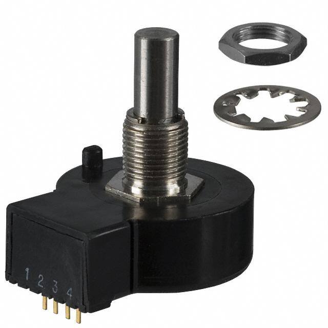
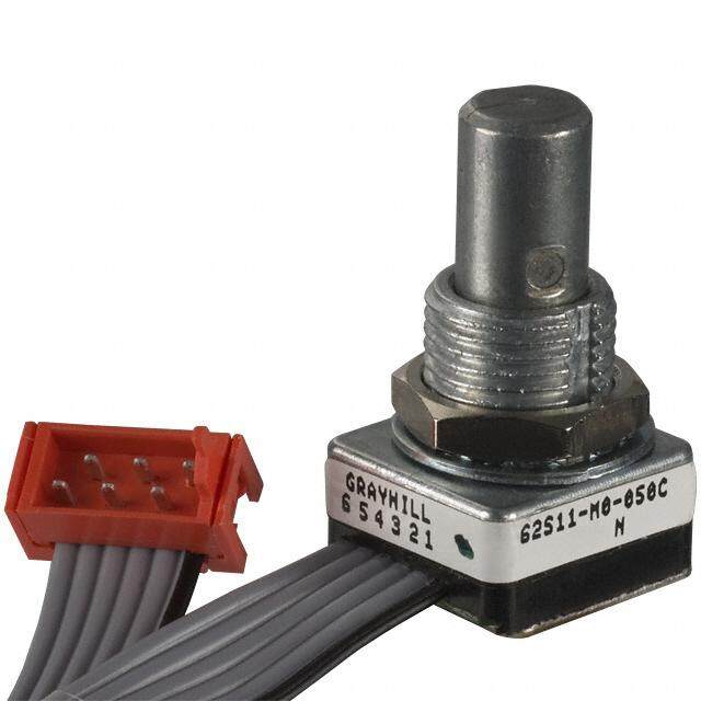
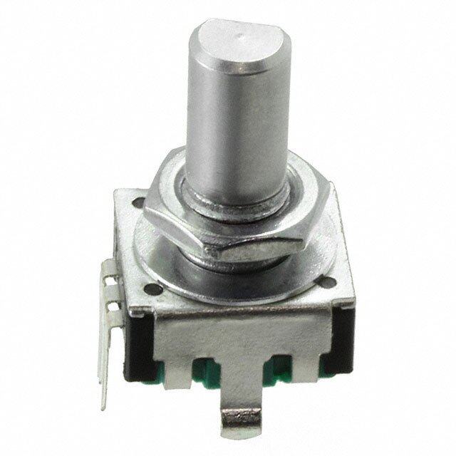
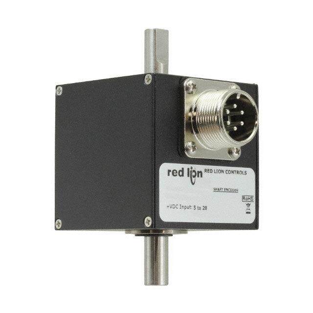
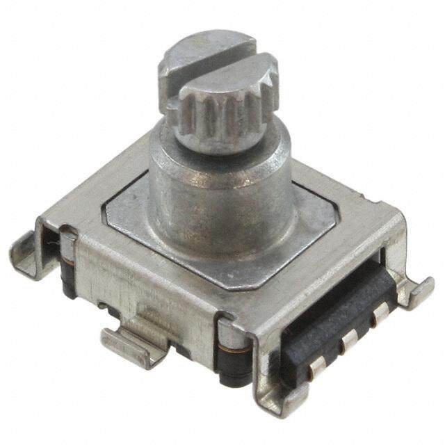
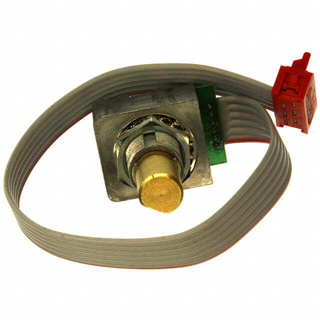
| 描述 | ENCODER OPTICAL ROTARY VERT PC编码器 128 pulse per rev 2-sq wave bottom ex |
| 产品分类 | |
| 品牌 | Honeywell Sensing and Control |
| 产品手册 | http://sensing.honeywell.com/index.cfm?ci_id=140301&la_id=1&pr_id=151847 |
| 产品图片 |
|
| rohs | 符合RoHS无铅 / 符合限制有害物质指令(RoHS)规范要求 |
| 产品系列 | Honeywell 600128C24600 |
| mouser_ship_limit | 该产品可能需要其他文件才能进口到中国。 |
| 数据手册 | http://sensing.honeywell.com/index.php?ci_id=47380 |
| 产品型号 | 600128C24 |
| 产品 | Optical Encoders |
| 产品目录绘图 |
|
| 产品目录页面 | |
| 产品种类 | |
| 其它名称 | 600-128-C24 |
| 内置开关 | 无 |
| 分辨率 | 128 PPR |
| 商标 | Honeywell |
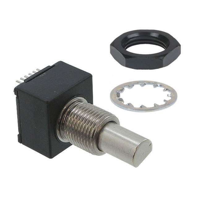
| 安装类型 | 面板,PCB 通孔 |
| 工作温度范围 | - 40 C to + 65 C |
| 工厂包装数量 | 180 |
| 带开关 | No Switch |
| 旋转寿命(最少次数) | 10M |
| 朝向 | 垂直 |
| 标准包装 | 180 |
| 棘爪 | 无 |
| 每转脉冲数 | 128 |
| 电压-电源 | 5V |
| 电源电压 | 5 VDC |
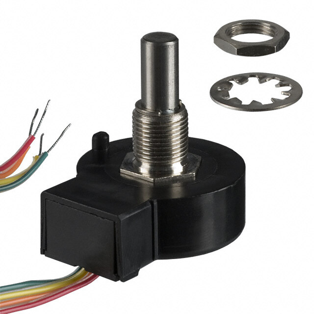
| 端子类型 | PC 引脚 |
| 编码器类型 | 光学 |
| 致动器类型 | 1/4" 直径圆形端头 |
| 输出 | Quadrature |
| 输出类型 | 正交(增量) |
| 通道数量 | 2 Channel |


- 商务部:美国ITC正式对集成电路等产品启动337调查
- 曝三星4nm工艺存在良率问题 高通将骁龙8 Gen1或转产台积电
- 太阳诱电将投资9.5亿元在常州建新厂生产MLCC 预计2023年完工
- 英特尔发布欧洲新工厂建设计划 深化IDM 2.0 战略
- 台积电先进制程称霸业界 有大客户加持明年业绩稳了
- 达到5530亿美元!SIA预计今年全球半导体销售额将创下新高
- 英特尔拟将自动驾驶子公司Mobileye上市 估值或超500亿美元
- 三星加码芯片和SET,合并消费电子和移动部门,撤换高东真等 CEO
- 三星电子宣布重大人事变动 还合并消费电子和移动部门
- 海关总署:前11个月进口集成电路产品价值2.52万亿元 增长14.8%


PDF Datasheet 数据手册内容提取
Optical Encoders 600 Series Datasheet
600 Series Optical Encoders The 600 Series Optical Encoders use non-contact technology to convert mechanical rotary motion into a digital electrical output. This output, compatible with transistor-transistor logic (TTL), may eliminate the need for analog to digital converters. These encoders are rotary devices which contain a rotor and stator pair that create a variable aperture to allow light from a light emitting diode (LED) to pass through to a photosensitive diode. The rotor represents the number of lines (pulses) of the encoder and the stator creates the positioning of the individual outputs, or phasing. The varying amount of light allowed through the aperture creates a sine wave output. Internal electronics then amplify and convert this sine wave output into a square wave. Two square waves, Channel A and Channel B, provide a quadrature output. Channel A leads Channel B by 90º electrically in a counterclockwise direction at a rate of 128 pulses per channel per revolution. Quadrature output allows the user to potentially determine incremental position, direction and speed. The 600 Series is available with PC terminals, cable, or cable with connector. Key Features and Benefits Potential Applications • Non-contact technology, with a minimum of 10 million INDuSTrIaL shaft rotations: Promotes long life in the application • Motor control • Digital voltage output: May eliminate the need for analog • Flow control to digital converters, contributes to a more cost-effective • Robotics solution • Computer peripherals • TTL-compatible output: Prevents triggering of false highs/ • Welding equipment lows due to ambient noise • Wide operating temperature range of -40 °C to 65 °C MEDICaL [-40 °F to 149 °F]: Promotes flexibility in the applications • Portable diagnostic equipment (i.e., EKG, ultrasound) • Choice of mounting terminations: Designed to provide • Home healthcare respiratory equipment mounting flexibility • Surgical equipment • Precision joysticks Longevity • cost-effective • fLexibiLity 2 sensing.honeywell.com
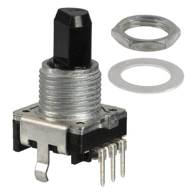
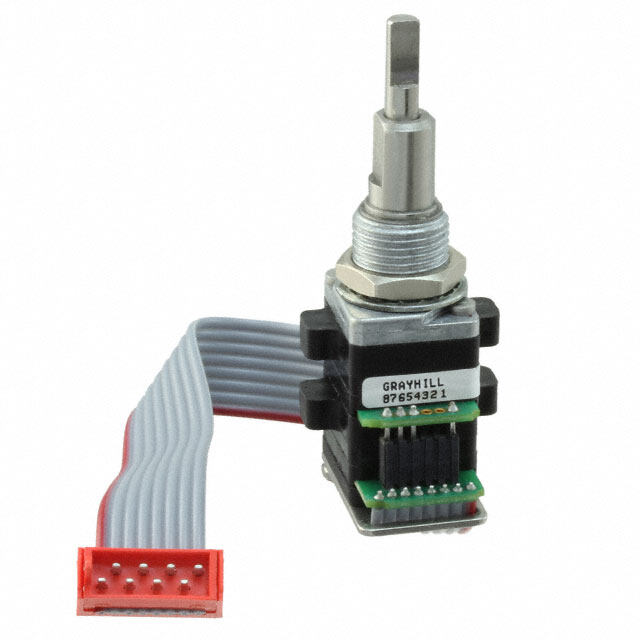
Optical Encoders, 600 Series Table 1. Electrical Specifications Parameter 600-128-C24 600-128-B66 600-128-CBL 600-128-CN1 Characteristic Electrical travel continuous/360º Input voltage 5 Vdc ±5% Output voltage: high 2.4 V min. with 10 kOhm load to ground low 0.4 V, max. Output rate 128 pulses/revolution per channel Supply current 30 mA, max. Channels two separate output channels in quadrature, 90º ±45º Table 2. Mechanical Specifications Parameter Characteristic 600-128-C24 600-128-B66 600-128-CBL 600-128-CN1 Mechanical travel continuous/360º Operating speed 300 RPM, max. Operating torque 0,011 N m [1.5 in oz], max. Rotational life 10 million shaft rotations, min. Shaft: diameter 6,35 mm [0.25 in] end play 0,127 mm [0.005 in], max. radial play 0,254 mm [0.010 in] at 25,4 mm [1 in] axial force 6,8 kg [15 lb] push/pull material stainless steel Bushing: diameter/thread size 9,53 mm [0.375 in] x 32 NEF 2A material nickel-plated brass cable with four-lead cable with Berg Termination type and PC, type C-24, 4-pin, PC, type B-66, 4-pin, ribbon, 28 AWG, connector, 28 AWG, material gold-plated gold-plated IL-W-168780 Type B or IL-W-168780 Type B or equivalent insulation equivalent insulation Terminal strength 2 lb push or pull Mounting hardware material: mounting nut nickel-plated brass lockwasher nickel-plated brass Sealing Controls are not sealed for board washing. Consult Honeywell for details. sensing.honeywell.com 3
Optical Encoders, 600 Series Table 3. Environmental Specifications Parameter Characteristic 600-128-C24 600-128-B66 600-128-CBL 600-128-CN1 Operating temperature -40 °C to 65 °C [-40 °F to 149 °F] Storage temperature -55 °C to 110 °C [-67 °F to 230 °F] Humidity 85 %RH at 40 °C [104 °F] 240 hr Figure 1. Mounting Dimensions (For reference only: mm [in].) 600-128-C24 ø28,58 [1.125] 13,49 [0.531] 3/8 X 32 NEF 2A ø3,18 [0.125] ø6,337 [0.2495] 17,45 [0.687] 20,62 [0.812] 14,06 12,29 17,45 [0.160] [0.484] [0.687] 12,7 [0.500] 1,91 [0.075] 9,53 [0.375] Mounting Nut Lock Washer 0,64 X 0,3 THK [0.025 X 0.012] 2,54 TYP. [0.100] 1,26 [0.050] 4 sensing.honeywell.com
Optical Encoders, 600 Series Figure 1. Mounting Dimensions (continued) 600-128-B66 ø28,58 [1.125] 12,29 13,49 [0.484] [0.531] 3/8 X 32 NEF 2A Mounting Nut ø6,337 [0.2495] Lock Washer ø3,18 12,7 [0.125] [0.500] 20,62 [0.812] 9,53 4,06 [0.375] [0.160] 0,64 X 0,3 Thick 11,51 2,54 Typ. [0.025 X 0.012] [0.453] [0.100] 1,26 [0.050] 17,45 [0.687] 600-128-CBL ø28,58 [1.125] 13,49 [0.531] 3/8 X 32 NEF 2A ø3,18 [0.125] 6,337 [0.2495] 17,45 [0.687] 20,62 [0.812] 9,53 191 12,29 17,45 [0.375] [7.50] [0.484] [0.687] 12,7 [0.500] 1,91 Mounting [0.075] Nut 9,53 [0.375] Lock Washer 28 AWG WIRE sensing.honeywell.com 5
Optical Encoders, 600 Series Figure 1. Mounting Dimensions (continued) 600-128-CN1 ø28,58 [1.125] 13,49 [0.531] 3/8 X 32 NEF 2A ø8,18 [0.125] ø6,337 [0.2495] 17,45 [0.687] 20,62 [0.812] 190,5 12,29 17,45 [7.50] [0.484] [0.687] 12,7 [0.500] 1,91 [0.075] 9,53 Mounting [0.375] Nut Lock Washer 28 AWG Wire Berg Connector 65039-32 1 2 3 4 5 Figure 2. Mounting Hardware Mounting Nut Lock Washer 3/8 in x 32 17,8 12,7 [0.70] [0.50] 6 sensing.honeywell.com
Optical Encoders, 600 Series Figure 3. Output Waveform 90º ±45º Phase Error 1 Output A 0 Logic 1 Level Output B 0 Channel A leads Channel B by 90º electrically in a CCW direction. Figure 4. Block Diagram 5 V 5.4 kOhm Output 1 Logic Circuit Ground 5.4 kOhm Output 2 Logic Circuit Table 4. Order Guide Catalog Listing Description 600-128-C24 600 Series optical encoder, PC terminal type C-24, vertical mounting, mounting hardware included 600-128-B66 600 Series optical encoder, PC terminal type B-66, horizontal mounting, mounting hardware included 600-128-CBL 600 Series optical encoder, 190,5 mm [7.5 in] cable, mounting hardware included 600-128-CN1 600 Series optical encoder, 190,5 mm [7.5 in] cable/connector, mounting hardware included sensing.honeywell.com 7
aDDITIONaL INFOrMaTION WARNING The following associated literature is available at sensing.honeywell.com: PERSONAL INJURY • Product Range Guide DO NOT USE these products as safety or emergency stop • Product Line Guide devices or in any other application where failure of the product • Installation Instructions could result in personal injury. Failure to comply with these instructions could result in death or serious injury. WARNING MISUSE OF DOCUMENTATION • The information presented in this product sheet is for reference only. Do not use this document as a product installation guide. • Complete installation, operation, and maintenance information is provided in the instructions supplied with each product. Failure to comply with these instructions could result in death or serious injury. WarraNTY/rEMEDY Honeywell warrants goods of its manufacture as being free of defective materials and faulty workmanship. Honeywell’s standard product warranty applies unless agreed to otherwise by Honeywell in writing; please refer to your order acknowledgement or consult your local sales office for specific warranty details. If warranted goods are returned to Honeywell during the period of coverage, Honeywell will repair or replace, at its option, without charge those items it finds defective. The foregoing is buyer’s sole remedy and is in lieu of all other warranties, expressed or implied, including those of merchantability and fitness for a particular purpose. In no event shall Honeywell be liable Find out more for consequential, special, or indirect damages. Honeywell serves its customers through a worldwide network While we provide application assistance personally, through our of sales offices, representatives literature and the Honeywell website, it is up to the customer to and distributors. For application determine the suitability of the product in the application. assistance, current specifications, pricing or name of the nearest Specifications may change without notice. The information we Authorized Distributor, contact supply is believed to be accurate and reliable as of this printing. your local sales office. However, we assume no responsibility for its use. To learn more about Honeywell’s sensing and control products, call +1-815-235-6847 or 1-800-537-6945, visit sensing.honeywell.com, or e-mail inquiries to info.sc@honeywell.com Sensing and Control Honeywell 1985 Douglas Drive North Golden Valley, MN 55422 32301269-A-EN IL50 October 2014 honeywell.com © 2014 Honeywell International Inc. All rights reserved.