ICGOO在线商城 > 工具 > 压接器,施用器,压力机 > 58529-1

 Datasheet下载
- 型号: 58529-1
- 制造商: CORCOM/TYCO ELECTRONICS
- 库位|库存: xxxx|xxxx
- 要求:
| 数量阶梯 | 香港交货 | 国内含税 |
| +xxxx | $xxxx | ¥xxxx |
查看当月历史价格
查看今年历史价格
58529-1产品简介:
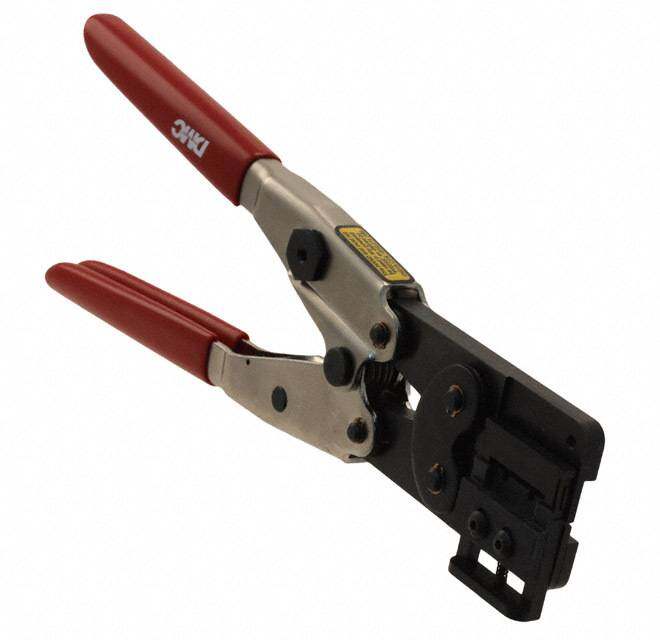
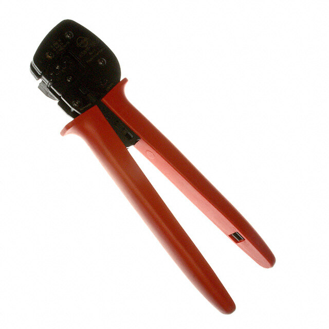
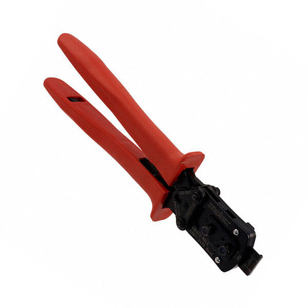
ICGOO电子元器件商城为您提供58529-1由CORCOM/TYCO ELECTRONICS设计生产,在icgoo商城现货销售,并且可以通过原厂、代理商等渠道进行代购。 58529-1价格参考¥1736.32-¥2052.84。CORCOM/TYCO ELECTRONICS58529-1封装/规格:压接器,施用器,压力机, 手动压接器 工具 矩形触点,16-20 AWG 侧面插入,棘齿。您可以下载58529-1参考资料、Datasheet数据手册功能说明书,资料中有58529-1 详细功能的应用电路图电压和使用方法及教程。
TE Connectivity AMP Connectors的58529-1型号压接器施用器主要用于电线端子的连接和固定,特别是在需要确保高效、可靠电气连接的场景中。以下是该工具的主要应用场景:

1. 汽车制造:在汽车生产线上,58529-1用于将电线端子压接到线束上,确保车内电子系统的稳定连接。无论是发动机控制单元、车灯系统还是娱乐设备,都需要高质量的电气连接,以保证车辆的安全性和功能性。

2. 工业自动化:在工厂自动化设备中,如机器人、传感器和控制系统,58529-1能够快速、精确地完成电线端子的压接,确保设备之间的信号传输稳定无误,减少故障率并提高生产效率。

3. 家电制造:在家电产品的组装过程中,如冰箱、洗衣机、空调等,58529-1可以确保内部电线与控制板之间的可靠连接,避免因接触不良导致的电器故障,延长产品使用寿命。

4. 通信设备:在通信基站、网络交换机等设备的安装和维护中,58529-1用于连接电源线、信号线等,确保数据传输的稳定性和可靠性,减少信号干扰和中断。

5. 航空航天:在航空电子设备和航天器的制造中,58529-1的应用至关重要。它能够确保复杂电子系统中的每一个连接点都具备极高的可靠性,满足严苛的工作环境要求。

6. 医疗设备:在医疗仪器和设备的组装中,58529-1用于连接各种传感器和监测设备,确保数据采集和传输的准确性,保障患者的诊断和治疗安全。

7. 建筑电气:在建筑物的电气系统安装中,如照明、安防和消防系统,58529-1可以确保电线与插座、开关等部件的稳固连接,提高整个系统的安全性。

总之,58529-1压接器施用器广泛应用于多个行业,凭借其高效、精准的压接能力,为各类电气连接提供了可靠的解决方案。
| 参数 | 数值 |
| 产品目录 | |
| 描述 | TOOL PRO-CRIMPER II W/DIE SET折皱器 PRO CRIMPER III |
| 产品分类 | |
| 品牌 | TE Connectivity |
| 产品手册 | |
| 产品图片 |
|
| rohs | 不可用不适用 / 不适用 |
| 产品系列 | 折皱器,TE Connectivity 58529-1Pro-Crimper III,AMPSEAL,AMP |
| 数据手册 | http://www.te.com/commerce/DocumentDelivery/DDEController?Action=srchrtrv&DocNm=408-9999&DocType=SS&DocLang=EN |
| 产品型号 | 58529-1 |
| 产品 | Crimpers |
| 产品种类 | 折皱器 |
| 其它名称 | 585291 |
| 商标 | TE Connectivity |
| 工具类型 | 手动压接器 |
| 工厂包装数量 | 1 |
| 标准包装 | 1 |
| 特性 | 侧面插入,棘齿 |
| 特色产品 | http://www.digikey.cn/product-highlights/zh/procrimper-iii-hand-tools/52602 |
| 类型 | Crimp Hand Tool |
| 视频文件 | http://www.digikey.cn/classic/video.aspx?PlayerID=1364138032001&width=640&height=505&videoID=3630218868001 |
| 配套使用产品/相关产品 | 矩形触点,18-20 AWG |


- 商务部:美国ITC正式对集成电路等产品启动337调查
- 曝三星4nm工艺存在良率问题 高通将骁龙8 Gen1或转产台积电
- 太阳诱电将投资9.5亿元在常州建新厂生产MLCC 预计2023年完工
- 英特尔发布欧洲新工厂建设计划 深化IDM 2.0 战略
- 台积电先进制程称霸业界 有大客户加持明年业绩稳了
- 达到5530亿美元!SIA预计今年全球半导体销售额将创下新高
- 英特尔拟将自动驾驶子公司Mobileye上市 估值或超500亿美元
- 三星加码芯片和SET,合并消费电子和移动部门,撤换高东真等 CEO
- 三星电子宣布重大人事变动 还合并消费电子和移动部门
- 海关总署:前11个月进口集成电路产品价值2.52万亿元 增长14.8%


PDF Datasheet 数据手册内容提取
InstructionSheet PRO-CRIMPER*IIIHand 408--9999 CrimpingToolAssembly58529-1 with DieAssembly58529-2 11AUG14 RevD PROPERUSEGUIDELINES CumulativeTraumaDisorderscanresultfromtheprolongeduseofmanuallypoweredhandtools.Handtoolsareintendedforoccasionaluseandlowvolume applications.Awideselectionofpoweredapplicationequipmentforextended--use,productionoperationsisavailable. LocatorAssembly StationaryJaw (Suppliedwith DieAssembly) BackofTool WireSide) FrontofTool (LocatorSide) PivotPin Die PRO--CRIMPERIIIHand Assembly CrimpingToolFrame MovingJaw 354940--1 (408--9930) Ratchet Adjustment Wheel Stationary ThePRO--CRIMPERIIIHandCrimpingToolisa“Commercial”gradetool Handle andisdesignedprimarilyforfieldinstallation,repair,maintenancework,or prototypinginindustrial,commercial,orinstitutionalapplications.Product crimpedwiththistoolwillmeetthecrimpheightrequirementforhandtoolsin MovingHandle theappropriate114seriesspecification,butmaynotcomplywithotherfeature parametersofthespecification.TEConnectivityoffersavarietyoftoolsto satisfyyourperformancerequirements.Foradditionalinformation,contactthe ToolingAssistanceCenterat1--800--722--1111. Wire TTEEDDiiee TTEELLooccaattoorr CCoonnttaacctt Assembly Assembly(cid:97) Family(cid:99) Size InsulDia StripLength (AWG) (mm[In.]) 16 5588552299----22 5588551155----11 AAMMPPSSEEAALL* 11..77ttoo22..77 55..1155..11(cid:225)(cid:225)..44 Contacts 18to20 [.07to.11] [.20(cid:225).02] (cid:97) Suppliedwiththedieassembly. Alsoavailableseparately. (cid:99) CalltheToolingAssistanceCenterorProductionInformation(seebelow)forproductpartnumbers. Figure1 1. INTRODUCTION NOTE Dimensionsonthissheetareinmillimeters[with inchequivalentsprovidedinbrackets].Figures PRO--CRIMPERIIIHandCrimpingTool i andillustrationsareforidentificationonlyandare Assembly58529--1consistsofDieAssembly notdrawntoscale. 58529--2andPRO--CRIMPERIIIHandToolFrame 354940--1.Thedieassemblyconsistsofcrimping diesandalocatorassembly. 2. DESCRIPTION(Figures1and2) Readtheseinstructionsthoroughlybeforecrimping anycontacts. Thetoolfeaturesatoolframewithastationaryjaw ReasonsforreissueareprovidedinSection11, andhandle,amovingjaw,amovinghandle,andan REVISIONSUMMARY. adjustableratchetthatensuresfullcontactcrimping. (cid:46)2014TEConnectivityfamilyofcompanies TOOLINGASSISTANCECENTER1--800--722--1111 Thiscontrolleddocumentissubjecttochange. 1of6 AllRightsReserved PRODUCTINFORMATION1--800--522--6752 ForlatestrevisionandRegionalCustomerService, *Trademark visitourwebsiteatwww.te.com TEConnectivity,TEconnectivity(logo),andTE(logo)aretrademarks. Otherlogos,productand/orCompanynamesmaybetrademarksoftheirrespectiveowners. LOCB
408-9999 Nut Locator Assembly ToolFrame Locator Insulation DieRetaing Chamfer Crimper Pins WireCrimper Offset WireAnvil Insulation Chamfer DieRetaining Anvil Screws Figure2 Thetoolframeholdsadieassemblywithtwo 5. Placethewirecrimperandinsulationcrimperso crimpingsections. thattheirchamferedsidesandtheirmarked surfacesfaceoutward,whenmountedinthe Thedieassemblyfeaturesawireanvil,aninsulation stationaryjawofthetoolframe. anvil,awirecrimper,andaninsulationcrimper. 6. Insertthetwodieretainingpins. Attachedtotheoutsideoftheframeisalocator assembly,whichcontainsalocator,aspringretainer, 7. Insertthelongdieretainingscrewthroughthe andacontactsupport. jawandthroughbothcrimperdies,andtightenthe screwjustenoughtoholdthediesinplace.Donot Dieretainingpinsanddieretainingscrewsareused tightenthescrewcompletelyatthistime. topositionandsecurethediesinthetoolframe.A 8. Carefullyclosethetoolhandles,makingsure nutisusedontheupperdieretainingscrewtohold thattheanvilsandcrimpersalignproperly. thelocatorassemblyinplace. 9. Continueclosingthetoolhandlesuntilthe ratchetinthetoolframehasengagedsufficientlyto 3. INSTALLATIONANDREMOVALOFDIESET holdtheanvilsandcrimpersinplace,thentighten ANDLOCATORASSEMBLY(Figure2) bothdieretainingscrews. 1. Openthetoolhandlesandremovethetwodie 10. Placethelocatorassemblyovertheendofthe retainingscrewsfromthetooljaws. longscrew,andpositionthelocatorassembly againstthesideofthetooljaw. 2. Placethewireanvilandinsulationanvilsothat theirchamferedsidesandtheirmarkedsurfaces 11. Placethenutontotheendofthelongscrew faceoutward,whenmountedinthemovingjawof andtightenthenutenoughtoholdthelocator thetoolframe. assemblyinplace,whilestillallowingthelocatorto slideupanddown. 3. Insertthetwodieretainingpins. 12. Todisassemble,closethetoolhandlesuntilthe 4. Inserttheshortdieretainingscrewthroughthe ratchetreleases,removethenut,thelocator jawandthroughbothanvildies,andtightenthe assembly,thetwodieretainingscrews,andthe screwjustenoughtoholdthediesinplace.Donot fourdieretainingpins,andslidetheanvilsand tightenthescrewcompletelyatthistime. crimpersoutofthetooljaws. 2of6 RevD
408-9999 4. CONTACTSUPPORTADJUSTMENT(Figure3) contactisstillbeingbentduringcrimping,repeat theadjustmentprocedure. NOTE Thecontactsupportispresetpriortoshipment, butminoradjustmentmaybenecessary. i 5. CRIMPINGPROCEDURE NOTE Thistoolisprovidedwithacrimpadjustment 1. Makeasamplecrimpanddetermineifthe feature.Initially,thecrimpheightshouldbe contactisstraight,bendingupward,orbending i verifiedasspecifiedinFigure4.Referto downward. Section6,CRIMPHEIGHTINSPECTION,and Section7,RATCHET ADJUSTMENT,toverify 2. Ifadjustmentisrequired,loosenthescrewthat crimpheightbeforeusingthetooltocrimp holdsthecontactsupportontothelocator desiredcontactsandwiresizes. assembly. RefertothetableinFigure1andselectwireofthe NOTE Theratchethasdetentsthatcreateaudibleclicks specifiedsizeandinsulationdiameter.Stripthewire asthetoolhandlesareclosed. tothelengthindicatedinFigure1,takingcarenotto i nickorcutwirestrands.Selectanapplicablecontact andidentifytheappropriatecrimpsectionaccording tothewiresizemarkingsonthetool.Referto 3. Placeacontactwithwireintothepropernest Figure3andproceedasfollows: andclosethetoolhandlesuntiltheratchetreaches thesixthclick,oruntilthecontactsupporttouches 1. Holdthetoolsothattheback(wireside)is thecontact. facingyou.Squeezetoolhandlestogetherand allowthemtoopenfully. 4. Slightlyloosenthenutthatholdsthelocator assemblyontothetoolframe. 2. Holdingthecontactbythematingend,insertthe contact—insulationbarrelfirst—throughthefront 5. Movethecontactsupportasrequiredto ofthetoolandintotheappropriatecrimpsection. eliminatethebendingofthecontact. 3. Positionthecontactsothatthematingendof 6. Tightenthenutandclosethehandlesuntilthe thecontactisonthelocatorsideofthetool,andso ratchetreleases. thattheopen“U”ofthewireandinsulationbarrels facethetopofthetool.Placethecontactupinto 7. Removeandinspectthecontact. thenestsothatthemovablelocatordropsintothe 8. Makeanothersamplecrimp.Ifthecontactis slotinthecontact.RefertoFigure3.Buttthefront straight,tightenthecontactsupportscrew.Ifthe endofthewirebarrelagainstthemovablelocator. Contact Locator Support BackofTool Adjustment (WireSide) Screwfor Contact Support Contact Strip (Typ) Length Wire Locator inWire Wire Slot Inserted toStop Figure3 RevD 3of6
408-9999 CAUTION Makesurethatbothsidesoftheinsulationbarrel Proceedasfollows: arestartedevenlyintothecrimpingsection.Do ! NOTattempttocrimpanimproperlypositioned 1. RefertoFigure4andselectawire(maximum contact. size)foreachcrimpsectionlisted. 2. RefertoSection5,CRIMPINGPROCEDURE, 4. Holdthecontactinpositionandsqueezethe andcrimpthecontact(s)accordingly. toolhandlestogetheruntilratchetengages sufficientlytoholdthecontactinposition.DoNOT 3. Usingacrimpheightcomparator,measurethe deforminsulationbarrelorwirebarrel. wirebarrelcrimpheightasshowninFigure4.Ifthe crimpheightconformstothatshowninthetable, 5. Insertstrippedwireintocontactinsulationand thetoolisconsidereddimensionallycorrect.Ifnot, wirebarrelsuntilitisbuttedagainstthewirestop, thetoolmustbeadjusted.RefertoSection7, asshowninFigure3. RATCHETADJUSTMENT. 6. Holdingthewireinplace,squeezetoolhandles togetheruntilratchetreleases.Allowtoolhandles 7. RATCHET(CrimpHeight)ADJUSTMENT(Figure5) toopenandremovecrimpedcontact. 1. Removethelockscrewfromtheratchet NOTE Thecrimpedcontactmaystickinthecrimping adjustmentwheel. area,butthecontactcanbeeasilyremovedby i pushingdownwardonthetopofthelocator(see 2. Withascrewdriver,adjusttheratchetwheel Figure3). fromthelocatorsideofthetool. 3. Observetheratchetadjustmentwheel.Ifa 7. Checkthecontact’scrimpheightasdescribedin tightercrimpisrequired,rotatetheadjustment Section6,CRIMPHEIGHTINSPECTION.If wheelCOUNTERCLOCKWISEtoa necessary,adjustthecrimpheightasdescribedin higher--numberedsetting.Ifaloosercrimpis Section7,RATCHETADJUSTMENT. required,rotatetheadjustmentwheel CLOCKWISEtoalower--numberedsetting. 4. Replacethelockscrew. 6. CRIMPHEIGHTINSPECTION 5. Makeasamplecrimpandmeasurethecrimp Crimpheightinspectionisperformedthroughtheuse height.Ifthedimensionisacceptable,replaceand ofamicrometerwithamodifiedanvil,commonly securethelockscrew.Ifthedimensionis referredtoasacrimp--heightcomparator.TEdoes unacceptable,continuetoadjusttheratchet,and notmanufactureormarketcrimp--heightcomparators. againmeasureasamplecrimp. Detailedinformationonobtainingandusing crimp--heightcomparatorscanbefoundininstruction sheet408--7424. Screwdriver PositionPoint onCenterof WireBarrel Opposite Seam ModifiedAnvil “A” Ratchet Adjustment WWiirreeSSiizzee CCrriimmppSSeeccttiioonn CCrriimmppHHeeiigghhtt Wheel AWG(Max) (WireSize Marking) DimensionA 18 20--18 1.22(cid:225).05 [.048(cid:225).002] 16 16 1.41(cid:225).05 Lockscrew [.056(cid:225).002] (Typ) Figure4 Figure5 4of6 RevD
408-9999 8. MAINTENANCE Availableseparately,PRO--CRIMPERIIIHand CrimpingToolRepairKit679221--1includesa Ensurethatthetoolanddiesarecleanbywiping replacementnutandavarietyofpins,rings,screws, themwithaclean,softcloth.Removeanydebriswith andsprings. aclean,softbrush.Donotuseobjectsthatcould damagethetool.Whennotinuse,keephandles Ifthediesaredamagedorwornexcessively,they closedtopreventobjectsfrombecominglodgedin mustbereplaced. thecrimpingdies,andstoreinaclean,dryarea. Ordertherepairkitandreplaceablepartsthrough yourTErepresentative,orcall1--800--526--5142,or 9. VISUALINSPECTION sendafacsimileofyourpurchaseorderto 1--717--986--7605,orwriteto: Thecrimpingdiesshouldbeinspectedonaregular basistoensurethattheyhavenotbecomewornor CUSTOMERSERVICE(38--35) damaged.Inspectthecrimpsectionsforflattened, TYCOELECTRONICS chipped,worn,orbrokenareas.Ifdamageor POBOX3608 abnormalwearisevident,thetoolmustbereplaced. HARRISBURGPA 17105--3608 SeeSection10,REPLACEMENT. 11.REVISIONSUMMARY 10. REPLACEMENT Revisionstothisinstructionsheetinclude: Customer--replaceablepartsareshowninFigure1. (cid:58) ChangedwiresizeintableinFigure1 RevD 5of6
408-9999 DieAssembly58529-2CanBeUsedIntheFollowingTools: PRO-CRIMPERIIIHandTool354940-1 SDEPEW-12HandTool9-1478240-0 (InstructionSheet408-9930) (InstructionSheet408-8851) SDEBenchTerminator1490076-2 626Adapter679304-1 (CustomerManual409-10052) (InstructionSheet408-4070) BatteryTool(ShoulderedDie)1725837-1, -2 BatteryTool(PinDie)1213890-1, -2 (CustomerManual409-10053) (CustomerManual409-10065) 6of6 RevD
Mouser Electronics Authorized Distributor Click to View Pricing, Inventory, Delivery & Lifecycle Information: T E Connectivity: 58529-1 58529-2