ICGOO在线商城 > Labels, Signs, Barriers, Identification > Accessories > 557401-001

 Datasheet下载
- 型号: 557401-001
- 制造商: GRAYHILL
- 库位|库存: xxxx|xxxx
- 要求:
| 数量阶梯 | 香港交货 | 国内含税 |
| +xxxx | $xxxx | ¥xxxx |
查看当月历史价格
查看今年历史价格
557401-001产品简介:
ICGOO电子元器件商城为您提供557401-001由GRAYHILL设计生产,在icgoo商城现货销售,并且可以通过原厂、代理商等渠道进行代购。 557401-001价格参考。GRAYHILL557401-001封装/规格:Accessories, Stop Pin Sticker。您可以下载557401-001参考资料、Datasheet数据手册功能说明书,资料中有557401-001 详细功能的应用电路图电压和使用方法及教程。
| 参数 | 数值 |
| 产品目录 | |
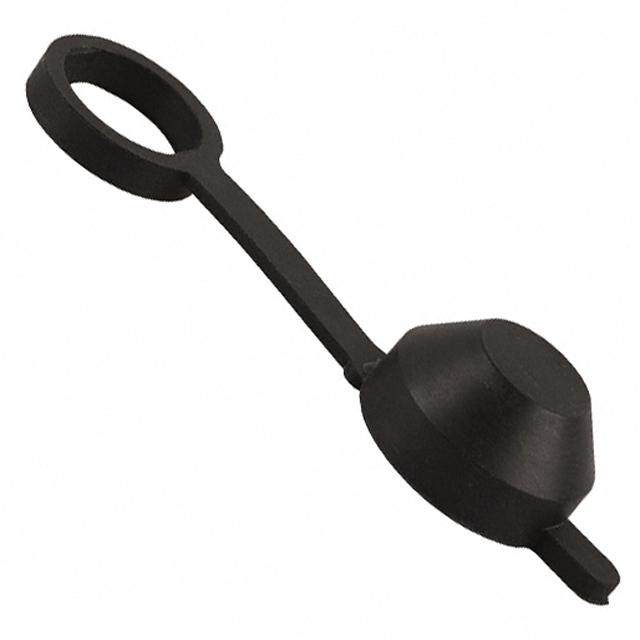
| 描述 | STICKER FOR STOP BLADE/PINS开关硬件 SILVER STICKER5K/RL 30deg |
| 产品分类 | |
| 品牌 | Grayhill |
| 产品手册 | |
| 产品图片 |
|
| rohs | 符合RoHS无铅 / 符合限制有害物质指令(RoHS)规范要求 |
| 产品系列 | 开关配件,开关硬件,Grayhill 557401-001- |
| 数据手册 | |
| 产品型号 | 557401-001 |
| 产品 | Labels |
| 产品种类 | 开关硬件 |
| 其它名称 | 557401001 |
| 商标 | Grayhill |
| 标准包装 | 1 |
| 配用 | /product-detail/zh/56DP36-01-2-AJN/GH7282-ND/764224/product-detail/zh/56DP36-01-1-AJN/GH7281-ND/764223/product-detail/zh/56DP30-01-2-AJN/GH7280-ND/764222/product-detail/zh/56DP30-01-1-AJN/GH7279-ND/483187/product-detail/zh/56D36-01-2-AJN/GH5604-ND/98655/product-detail/zh/56D36-01-1-AJN/GH5603-ND/98652/product-detail/zh/56D30-01-2-AJN/GH5602-ND/98649/product-detail/zh/56D30-01-1-AJN/GH5601-ND/98646 |


- 商务部:美国ITC正式对集成电路等产品启动337调查
- 曝三星4nm工艺存在良率问题 高通将骁龙8 Gen1或转产台积电
- 太阳诱电将投资9.5亿元在常州建新厂生产MLCC 预计2023年完工
- 英特尔发布欧洲新工厂建设计划 深化IDM 2.0 战略
- 台积电先进制程称霸业界 有大客户加持明年业绩稳了
- 达到5530亿美元!SIA预计今年全球半导体销售额将创下新高
- 英特尔拟将自动驾驶子公司Mobileye上市 估值或超500亿美元
- 三星加码芯片和SET,合并消费电子和移动部门,撤换高东真等 CEO
- 三星电子宣布重大人事变动 还合并消费电子和移动部门
- 海关总署:前11个月进口集成电路产品价值2.52万亿元 增长14.8%


PDF Datasheet 数据手册内容提取
Single Deck Rotary Switches SERIES 56 0.5" Diameter, 200mA, .355" Behind Panel FEATURES • Requires Minimum Distance Behind the Panel • Adjustable Stop Types Provide Prototypes Immediately • Industrial Quality, Economically Priced • RoHS Compliant DIMENSIONS in inches (and millimeters) PC Mount Style .377 .203 ± .003 .250 ± .015 ± .020 PC TERMINAL DETAIL (5,16 ± 0,08) (6,35 ± 0,38) (9,58 .110 ± .015 .016 ± .004 ACROSS .375 ± .015 ± 0,51) (2,79 ± 0,38) (0,4 ± 0,10) BUSHING (9,53 ± 0,38) .110 FLATS .250 ± .015 ± .015 A (6,35 ± 0,38) (2,79 .500 LL9 ± 0,38) .(001,46 ±± 0.0,1004) SQ. .(014,26 ±± 0.0,1004) Ø HI10 ± .015 Y FOR REAR (12,70 RA1 VIEWS, SEE ± 0,25) POS. 1 G2 FOLLOWING Ø .125 ± .002 PAGE. (3,18 ± 0,06) PC COMMON .110 ± .015 R o (2,79 ± 0,38) tary S .(029,349 ± ± . 001,205) 1T/H4R-2E8A UDNF-2A w itche ANGLE OF ANGLE Ø(0 ,.6042 5± ±0 ,.0050)2 s THROW A 30° 105° 36° 108° Grayhill part number and date code marked on label. Customer part number marked on request. Solder Lug Style SOLDER LUG TERMINAL DETAIL .203 ± .003 .250 ± .015 .480 ± .020 (5,16 ± 0,08) (6,35 ± 0,38) (12,19 ± 0,51) .063 ± .005 .016 ± .004 ACROSS BUSHING .375 ± .015 (1,60 ± 0,13) (0,41 ± 0,10) FLATS (9,53 ± 0,38) .125 ± .015 .250 ± .015 (3,18 ± 0,38) A (6,35 ± 0,38) .500 LL9 FOR REAR Ø HI10 VIEWS, SEE .020 ± .004 .046 ± .004 ± .015 Y (0,51 ± 0,10) (1,17 ± 0,10) (12,70 RA1 FPAOGLLEO.WING ± 0,38) POS. 1 Ø .125 ± .002 G2 (3,18 ± 0,06) SOLDER LUG COMMON .125 ± .015 .094 ± .010 1/4-28 UNF-2A (3,18 ± 0,38) (2,39 ± 0,25) THREAD ANGLE OF ANGLE THROW A Ø .062 ± .002 30° 105° (1,58 ± 0,51) 36° 108° Grayhill part number and date code marked on label. Customer part number marked on request. Grayhill, Inc. • 561 Hillgrove Avenue • LaGrange, Illinois 60525-5997 • USA • Phone: 708-354-1040 • Fax: 708-354-2820 • www.grayhill.com
Single Deck Rotary Switches CIRCUIT DIAGRAMS AND REAR VIEWS: PC Mountable AND Solder Lug Terminals Rear View Circuit as Viewed From Shaft End .366 ± .015 .366 ± .015 (9,30 ± 0,38) (9,30 ± 0,38) 9 10 DIA. CIRCLE DIA. CIRCLE 8 11 OF CENTERS OF CENTERS 7 12 30° Angle .190 ± .015 (4,83 ± 0,38) .190 ± .015 (4,83 ± 0,38) 6 1 of Throw 15° DIA. CIRCLE OF CENTERS 15° DIA. CIRCLE OF CENTERS (PC MOUNT AND (PC MOUNT AND 5 2 POS. 1 SOLDER LUG) POS. 1 SOLDER LUG) 4 3 30° TYP. 30° TYP. ONE POLE COMMON LOCATION FOR 2 POLE SWITCH 9 10 9 10 8 11 8 11 7 C2 12 7 C3 12 COMMON LOCATION C4 FOR 1 POLE SWITCH 6 C1 1 6 C2 C1 1 5 2 5 2 4 3 4 3 TWO POLES FOUR POLES .340 ± .015 (8,64 ± 0,38) DIA. CIRCLE OF CENTERS 8 8 7 9 7 9 6 10 6 C2 10 36° Angle DIMENSION A 18° DIA. CIRCLE OF CENTERS 5 1 5 C1 1 of Throw POS. 1 36° TYP. 4 2 4 2 3 3 COMMON LOCATION PC Mount Solder Lug FOR 2 POLE SWITCH ONE POLE TWO POLES Dimension Terminals Terminals COMMON LOCATION A .184 ± .015 .126 ± .015 FOR 1 POLE SWITCH (4,67 ± 0,38) (3,20 ± 0,38) R o ta SPECIFICATIONS ry Electrical Ratings Materials and Finishes Sw Chart shown for non-shorting (break before make) elevated temperatures or reduced pressures. Housing: Zinc die cast. Tin Zinc or Sulfamate itc h contacts, resistive load. Contact Carry Rating: Switch will carry 6 Nickel Plated e PS amperes continuously with a maximum Mounting Nut: Brass. Tin Zinc or Sulfamate s M A300 contact temperature rise of 20°C. Nickel Plated LI L Lockwasher: Spring steel, zinc plated MI200 T - Additional Characteristics Panel Seal: Silicone rubber EN100 Contact Type and Forces: Shorting or non- Shaft and Stop Arm: Machined, 303 Stainless CURR 0 0 10 20 30 schoonrtatinctg f owricpein.g contacts with over 25 grams of SRteeteali,n oinr gC oRldin Fgo: rSmtaeidn,l e4s3s0 s Stetaeilnless Steel Shaft Flat Orientation: Flat opposite contacting Shaft Seal: Fluorosilicone rubber 1C15Y CVLaEc S0 rx 3 100 V0d0c position of pole number one (see circuit Stop Pins: Stainless steel diagrams). Detent Rotor: Molded thermoplastic One cycle is 360° rotation clockwise and 360° Terminals: Switches have the full circle of Detent Spring: Music wire return. The data for the curve was measured at terminals, regardless of number of active Detent Balls: Steel, nickel-plated sea level, 25°C and 68% relative humidity with positions. Contact Spring: Stainless steel the life limiting criteria which follows. Stop Strength: 7.5 lb-in. minimum Rotor Contact: Brass or zinc alloy, silver over Contact Resistance: 100 milliohms maximum, Rotational Torque: 3.5 to 9 oz-in. (21-53 nickel plate (15 milliohms initially). mN-m), depending on the number of poles. Common Ring: Brass, gold over silver over Insulation Resistance: 10,000 Mohms Bushing Mounting: Required for switches with nickel plate minimum between mutually insulated parts stops, and recommended for switches without Terminals: Brass, gold over silver over nickel (50,000 Mohms initially). stops. plate Voltage Breakdown: 600 Vac minimum Meets MIL-DTL-3786 for: between mutually insulated parts at standard High and medium shock; Vibration (10 to 2,000 atmospheric pressure. Hz); Thermal shock (-65° to 85 ° C); Salt spray; Life Expectancy: As determined from the Explosion; Stop strength (7.5 in-lbs. minimum (.85 load-life curve for the current to be switched. N-m); Terminal strength; Sealed styles withstand Contact GRAYHILL for more information if any water pressure of 15 PSI minimum (103 KPa) of the following is true: the life limiting criteria are without leakage. more critical than those listed; longer operation is required; a larger make and break current is required; the operating environment includes Grayhill, Inc. • 561 Hillgrove Avenue • LaGrange, Illinois 60525-5997 • USA • Phone: 708-354-1040 • Fax: 708-354-2820 • www.grayhill.com
Single Deck Rotary Switches SHAFT AND PANEL SEAL: Style S Panel is sealed by a flat rub- ber seal washer at the base of bushing. Shaft is sealed by an O-ring inside the bushing. After the switch is mounted, seals do not alter the dimensions of the Shaft and unsealed style. Panel Seal SCREWDRIVER SLOTTED SHAFT: Option Series 56 rotary switches are available with a screwdriver slotted shaft with dimensions as Screwdriver shown. Available in the styles, Slotted Shaft angles of throw and pole/posi- tions combinations shown in the choice and limitations chart. ADJUSTABLE STOP SWITCHES Rota Tsewaol swtaosph peinr sa aren pdr aonv iaddehde. sSivtieck bearc ikse tedm stpicokrearr iolyr tthoe t hseh afifxte rdo tsattoiopn s. wAlilt cdhim ceonusnitoenrpsa arrt.e identical AStdojupstable ry removed to locate stop pins as desired to limit S w itc h e s ACCESSORY: Non-Turn Washer In Inches (and millimeters) .400 .025 ADJUSTABLE ADJUSTABLE ± .005 ± .001 STOP PINS STOP PINS DIA. (0,64 (10,16 ± 0,03) REMOVABLE REMOVABLE ± 0,13) 90° ± 1° STICKER FOR SEAL WASHER ADJUSTMENT FOR ADJUSTMENT .250 ± .003 .015 OF STOPS OF STOPS (6,35 ± 0,08) (0,38) RADIUS MAX. .125 .060 ± .001 ± .005 (1,52 ± 0,25) (3,16 SUGGESTED ADJUSTABLE STOP SUBSTITUTION GUIDE ± 0,13) Fixed Stop Adjustable Stop Fixed Stop Adjustable Stop Part No. 50J1066 Style Style Equivalent Style Style Equivalent Cut round hole for the bushing and for 56A 56D 56B 56BD the non-turn tab. Washer fits the double 56S 56SD 56BS 56BSD D bushing flats. Washer is sold only when 56P 56DP 56BP 56BDP accompanied by an order for a like number 56SP 56SDP 56BSP 56BSDP of switches. Washer is 302 stainless steel. Grayhill, Inc. • 561 Hillgrove Avenue • LaGrange, Illinois 60525-5997 • USA • Phone: 708-354-1040 • Fax: 708-354-2820 • www.grayhill.com
Single Deck Rotary Switches CHOICES AND LIMITATIONS: Series 56 A = Standard, 1/8" Shaft P = PC Mount Terminals B = Screwdriver Slot Shaft S = Shaft/Panel Seal (S/P Seal) D = Adjustable Stop (Adj. Stop) FEATURES Screwdriver Angle Number Number Of Shorting Or Style Solder Lug PC Mo u n t S h a f t / P a n e l A djustable Slotted Shaft Of Of Positions Non-Shorting D esignation Terminals Termi n a l s S e a l S t o p s 1 E q u i v a l e n t Throw Poles Per Pole Contacts A X B S X X BS 1 02 thru 12 N or S P X BP 30° 2 02 thru 06 N or S 4 02 or 03 N or S SP X X BSPD X X BD SD X X X BSD 1 02 thru 10 N or S DP X X BDP 36° 2 02 thru 05 N or S SDP X X X BSDP 1 Adjustable stop versions allow selection of 2 positions to the maximum number of positions per pole. STANDARD OPTIONS ORDERING INFORMATION Available from your local Grayhill Distributor For prices and discounts, contact a local Sales Series Office, an authorized local Distributor, or Grayhill. Style: Letters from Choices Chart Not available thru Distributors when Intermixing Angle of Throw: 30 or 36° of shorting and non-shorting contacts. Contact Grayhill. 56A36S–01–1–10N–F Stop Arrangement: The suffix C or F must be added to a one pole per deck switch with the maximum number of positions to indicate continuous rotation (C) or fixed stops (F) between posi- tion 1 and the last position. Ro Type of Contacts: N = Non-shorting, S = Shorting tary Positions Per Pole: 02 as a minimum to the maximum S w allowable for the angle of throw and number of poles per the itc Choices Chart. Use the letters AJ in this location if adjustable h e stop switch is to be ordered. s Poles per Deck: Limited by angle of throw. See chart Number of Decks: 01 only Shafts: S= Machined, Blank= Cold Formed Grayhill, Inc. • 561 Hillgrove Avenue • LaGrange, Illinois 60525-5997 • USA • Phone: 708-354-1040 • Fax: 708-354-2820 • www.grayhill.com