ICGOO在线商城 > 501R18W471KV4E
- 型号: 501R18W471KV4E
- 制造商: Johanson Dielectrics Inc.
- 库位|库存: xxxx|xxxx
- 要求:
| 数量阶梯 | 香港交货 | 国内含税 |
| +xxxx | $xxxx | ¥xxxx |
查看当月历史价格
查看今年历史价格
501R18W471KV4E产品简介:
ICGOO电子元器件商城为您提供501R18W471KV4E由Johanson Dielectrics Inc.设计生产,在icgoo商城现货销售,并且可以通过原厂、代理商等渠道进行代购。 提供501R18W471KV4E价格参考以及Johanson Dielectrics Inc.501R18W471KV4E封装/规格参数等产品信息。 你可以下载501R18W471KV4E参考资料、Datasheet数据手册功能说明书, 资料中有501R18W471KV4E详细功能的应用电路图电压和使用方法及教程。
| 参数 | 数值 |
| 产品目录 | |
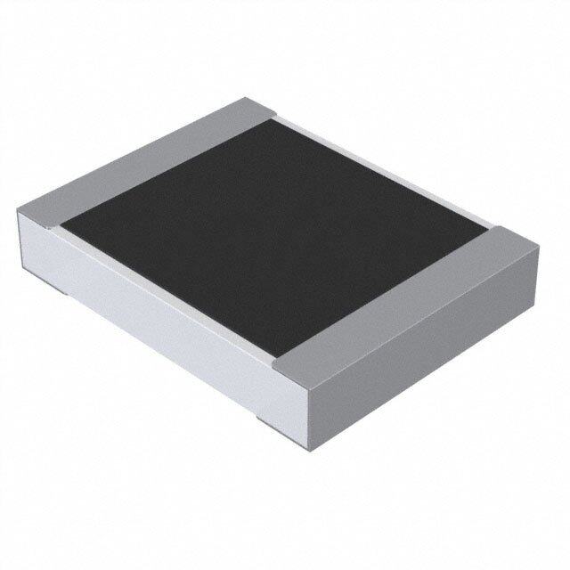
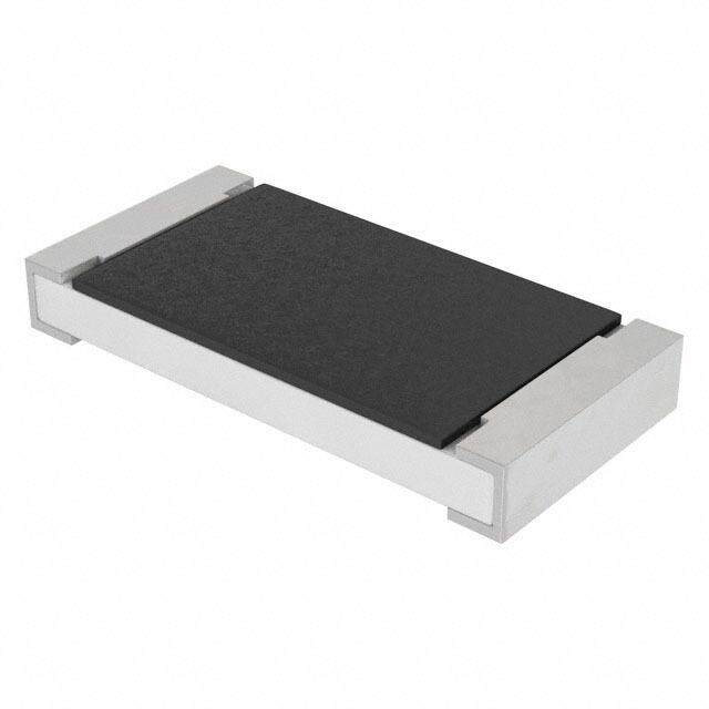
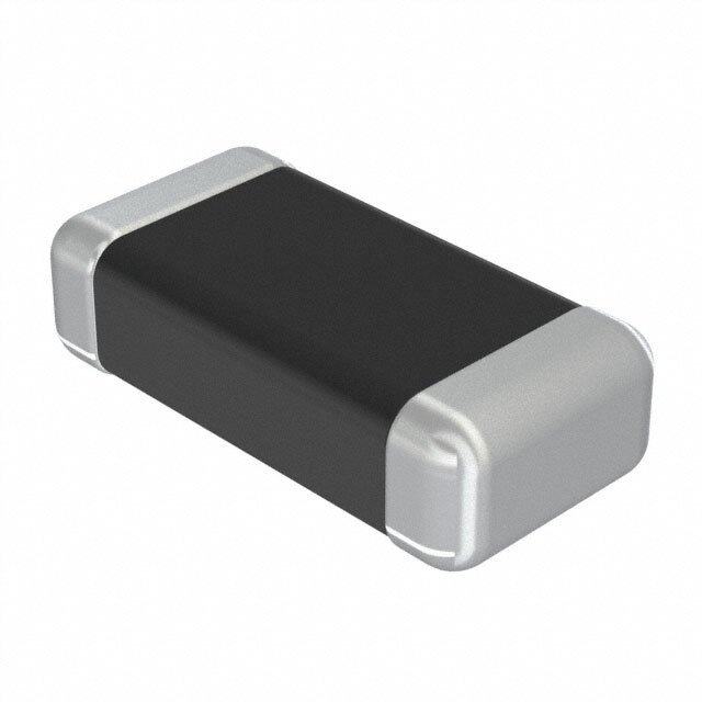
| 描述 | CAP CER 470PF 500V 10% X7R 1206多层陶瓷电容器MLCC - SMD/SMT 500volts 470pF 10% X7R |
| 产品分类 | |
| 品牌 | Johanson Dielectrics |
| 产品手册 | |
| 产品图片 |
|
| rohs | 符合RoHS无铅 / 符合限制有害物质指令(RoHS)规范要求 |
| 产品系列 | MLCC,多层陶瓷电容器MLCC - SMD/SMT,Johanson Dielectrics 501R18W471KV4E- |
| mouser_ship_limit | 该产品可能需要其他文件才能进口到中国。 |
| 数据手册 | |
| 产品型号 | 501R18W471KV4E |
| 产品 | General Type MLCCs |
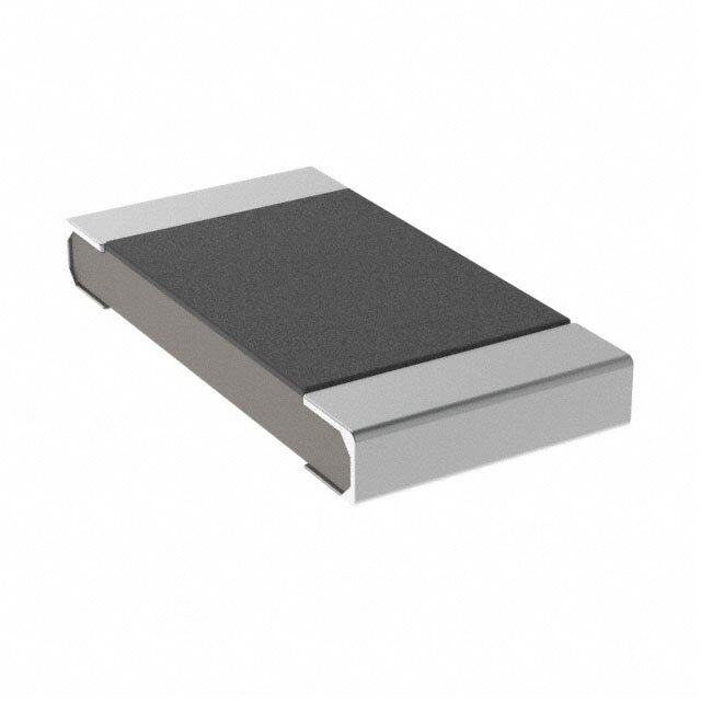
| 产品目录绘图 |
|
| 产品目录页面 | |
| 产品种类 | 多层陶瓷电容器MLCC - SMD/SMT |
| 其它名称 | 709-1281-1 |
| 包装 | 剪切带 (CT) |
| 厚度(最大值) | 0.050"(1.27mm) |
| 商标 | Johanson Dielectrics |
| 外壳代码-in | 1206 |
| 外壳代码-mm | 3216 |
| 外壳宽度 | 1.57 mm |
| 外壳长度 | 3.17 mm |
| 外壳高度 | 1.7 mm |
| 大小/尺寸 | 0.125" 长 x 0.062" 宽(3.17mm x 1.57mm) |
| 安装类型 | 表面贴装,MLCC |
| 容差 | 10 % |
| 封装 | Reel |
| 封装/外壳 | 1206(3216 公制) |
| 封装/箱体 | 1206 (3216 metric) |
| 工作温度 | -55°C ~ 125°C |
| 工作温度范围 | - 55 C to + 125 C |
| 工具箱 | /product-detail/zh/S-500/709-1248-ND/2236958 |
| 工厂包装数量 | 3000 |
| 应用 | 通用 |
| 引线形式 | - |
| 引线间距 | - |
| 最大工作温度 | + 125 C |
| 最小工作温度 | - 55 C |
| 标准包装 | 1 |
| 温度系数 | X7R |
| 温度系数/代码 | +/- 15 % |
| 特性 | 高电压 |
| 电介质 | X7R |
| 电压-额定 | 500V |
| 电压额定值 | 500 V |
| 电压额定值DC | 500 V |
| 电容 | 470 pF |
| 端接类型 | SMD/SMT |
| 等级 | - |
| 类型 | Tanceram High Voltage |
| 高度-安装(最大值) | - |

PDF Datasheet 数据手册内容提取
H V S MLCC 250 - 6,000 VDC IGH OLTAGE URFACE MOUNT S These high voltage capacitors feature a special internal electrode design which reduces voltage concentrations by distributing voltage gradients throughout the entire capacitor. This unique design also affords increased capacitance values in a given case size and voltage rating. The capacitors are designed and manufactured to the general requirement of EIA198 and are subjected to a 100% electrical testing making them well suited for a wide variety of telecommunication, commercial, and industrial applications. APPLICATIONS • Analog & Digital Modems • LAN/WAN Interface • Lighting Ballast Circuits • Voltage Multipliers • DC-DC Converters • Back-lighting Inverters NOW AVAILABLE with Polyterm ® soft termination option for demanding environments & processes. Visit our website for full details. Mechanical Characteristics Available Capacitance Rated NPO Dielectric X7R Dielectric Voltage Minimum Maximum Minimum Maximum Inches (mm) 250 VDC - - 1000 pF 0.022 µF R15/0805 L .080 ±.010 (2.03 ±.25) 500 VDC 10 pF 680 pF 1000 pF 0.010 µF W .050 ±.010 (1.27 ±.25) 630 VDC 10 pF 560 pF 1000 pF 3900 pF T .055 Max. (1.40) 1000 VDC 10 pF 390 pF 100 pF 3300 pF E/B .020 ±.010 (0.51±.25) Inches (mm) 250 VDC - - 1000 pF 0.068 µF R18/1206 L .125 ±.010 (3.17 ±.25) 500 VDC 10 pF 1500 pF 1000 pF 0.047 µF W .062 ±.010 (1.57 ±.25) 630 VDC 10 pF 1200 pF 1000 pF 0.027 µF T .067 Max. (1.70) 1000 VDC 10 pF 1000 pF 100 pF 0.018 µF E/B .020 ±.010 (0.51±.25) 2000 VDC 10 pF 220 pF 100 pF 1000 pF 3000 VDC 10 pF 82 pF 100 pF 220 pF Inches (mm) 250 VDC - - 1000 pF 0.120 µF S41/1210 L .125 ±.010 (3.18 ±.25) 500 VDC 10 pF 3900 pF 1000 pF 0.082 µF W .095 ±.010 (2.41 ±.25) 630 VDC 10 pF 2700 pF 1000 pF 0.056 µF T .080 Max. (2.03) 1000 VDC 10 pF 1800 pF 100 pF 0.027 µF E/B .020 ±.010 (0.51±.25) 2000 VDC 10 pF 560 pF 100 pF 2200 pF 3000 VDC 10 pF 220 pF 100 pF 560 pF Inches (mm) 500 VDC 10 pF 4700 pF 1000 pF 0.056 µF R29/1808 L .185 ±.015 (4.80 ±.25) 630 VDC 10 pF 3300 pF 1000 pF 0.047 µF W .080 ±.010 (2.03 ±.25) 1000 VDC 1.0 pF 2200 pF 100 pF 0.033 µF T .085 Max. (2.16) 2000 VDC 1.0 pF 820 pF 100 pF 6800 pF E/B .020 ±.010 (0.51±.25) 3000 VDC 1.0 pF 470 pF 100 pF 3300 pF 4000 VDC 1.0 pF 180 pF 100 pF 270 pF 5000 VDC 1.0 pF 75 pF 47 pF 120 pF 6000 VDC 1.0 pF 75 pF 47 pF 100 pF Available capacitance values include the following significant retma values and their multiples: 1.0 1.2 1.5 1.8 2.2 2.7 3.3 3.9 4.7 5.6 6.8 8.2 ( 1.0 = 1.0, 10, 100, 1000, etc.) Consult factory for non-retma values and sizes or voltages not shown. 6 www.johansondielectrics.com
H V S M MLCC 250 - 6,000 VDC IGH OLTAGE URFACE OUNT S Mechanical Characteristics Available Capacitance Rated NPO Dielectric X7R Dielectric Voltage Minimum Maximum Minimum Maximum 250 VDC - - 0.010µF 0.270uF S43 / 1812 Inches (mm) 500VDC 100pF 8200pF 1000pF 0.150uF L .180 ±.010 (4.57 ±.25) 630VDC 100pF 6800pF 1000pF 0.100µF W .125 ±.010 (3.17 ±.25) 1000VDC 10pF 5600pF 1000pF 0.056µF T .110 Max. (2.80) 2000VDC 10pF 1800pF 100pF 6800pF E/B .025 ±.015 (0.64±.38) 3000VDC 10pF 1000pF 100pF 4700pF 4000VDC 10pF 390pF 100pF 1500pF 5000VDC 10pF 150pF 100pF 680pF 6000VDC 10pF 150pF 10pF 680pF 500VDC 100pF 0.018µF 0.01µF 0.330µF S49 / 1825 Inches (mm) 630VDC 100pF 0.015µF 0.01µF 0.220µF L .180 ±.010 (4.57 ±.25) 1000VDC 10pF 0.012µF 1000pF 0.039µF W .250 ±.010 (6.35 ±.25) 2000VDC 10pF 5600pF 100pF 0.018µF T .140 Max. (3.56) 3000VDC 10pF 2200pF 100pF 8200pF E/B .025 ±.015 (0.64±.38) 4000VDC 10pF 1200pF 100pF 2000pF 5000VDC 10pF 390pF 100pF 820pF 6000VDC 10pF 390pF 100pF 820pF 500VDC 1000pF 0.018µF 0.01µF 0.330µF S47 / 2220 Inches (mm) 630VDC 1000pF 0.018µF 0.01µF 0.270µF L .225 ±.015 (5.72 ±.38) 1000VDC 100pF 0.015µF 1000pF 0.056µF W .200 ±.015 (5.08 ±.38) 2000VDC 100pF 5600pF 1000pF 0.027µF T .150 Max. (3.81) 3000VDC 10pF 2700pF 100pF 0.010µF E/B .025 ±.015 (0.64±.38) 4000VDC 10pF 1500pF 100pF 2200pF 5000VDC 10pF 470pF 100pF 1500pF 6000VDC 10pF 470pF 100pF 1500pF 500VDC 1000pF 0.027µF 0.01µF 0.470µF S48 / 2225 Inches (mm) 630VDC 1000pF 0.022µF 0.01µF 0.330µF L .225 ±.010 (5.72 ±.25) 1000VDC 100pF 0.018µF 1000pF 0.120µF W .255 ±.015 (6.48 ±.38) 2000VDC 100pF 8200pF 1000pF 0.039µF T .160 Max. (4.06) 3000VDC 10pF 3300pF 100pF 0.015µF E/B .025 ±.015 (0.64±.38) 4000VDC 10pF 1800pF 100pF 5600pF 5000VDC 10pF 470pF 100pF 1500pF 6000VDC 10pF 470pF 100pF 1500pF Available capacitance values include the following significant retma values and their multiples: 1.0 1.2 1.5 1.8 2.2 2.7 3.3 3.9 4.7 5.6 6.8 8.2 ( 1.0 = 1.0, 10, 100, 1000, etc.) Consult factory for non-retma values and sizes or voltages not shown. ELECTRICAL CHARACTERISTICS W L Meets the standard NPO & X7R dielectric specifications listed on page 20 Dielectric Withstanding Voltage DWV = 1.5 X rated WVDC for ratings ≤ 500 WVDC, T E/B DWV = 1.2 X rated WVDC for ratings ≥ 1,000 WVDC NOTE: Capacitors may require a surface coating to prevent external arcing. Solder mask should not be used beneath capacitors. For more information see JDI Tech Note “Surface Arc Season” HOW TO ORDER Part number written: 202R29N101KV4E 202 R29 N 101 K V 4 E VOLTAGE CASE SIZE CAPACITANCE TOLERANCE TERMINATION MARKING TAPE MODIFIER 501 = 500 V See Chart 1st two digits are NPO: J = ± 5% V = Ni barrier w/ 4 = Unmarked Code Tape Reel 631 = 630 V significant; third digit K = ± 10% 100% Sn Plating 6 = EIA Code* E Embossed 7” 102 = 1000 V denotes number of F = Polyterm U Embossed 13” 202 = 2000 V DIELECTRIC zeros, R = decimal. X7R: K = ± 10% flexible termination T Paper 7” 302 = 3000 V N = NPO/COG 1R0 = 1.0 pF M = ± 20% R Paper 13” 402 = 4000 V W = X7R 101 = 100 pF Tape specs. per EIA RS481 502 = 5000 V 602 = 6000 V www.johansondielectrics.com 7

 Datasheet下载


