ICGOO在线商城 > 射频/IF 和 RFID > RF 评估和开发套件,板 > 4012-LCDK1W-434
- 型号: 4012-LCDK1W-434
- 制造商: Silicon Laboratories
- 库位|库存: xxxx|xxxx
- 要求:
| 数量阶梯 | 香港交货 | 国内含税 |
| +xxxx | $xxxx | ¥xxxx |
查看当月历史价格
查看今年历史价格
4012-LCDK1W-434产品简介:
ICGOO电子元器件商城为您提供4012-LCDK1W-434由Silicon Laboratories设计生产,在icgoo商城现货销售,并且可以通过原厂、代理商等渠道进行代购。 4012-LCDK1W-434价格参考¥612.86-¥612.86。Silicon Laboratories4012-LCDK1W-434封装/规格:RF 评估和开发套件,板, 。您可以下载4012-LCDK1W-434参考资料、Datasheet数据手册功能说明书,资料中有4012-LCDK1W-434 详细功能的应用电路图电压和使用方法及教程。
| 参数 | 数值 |
| 产品目录 | |
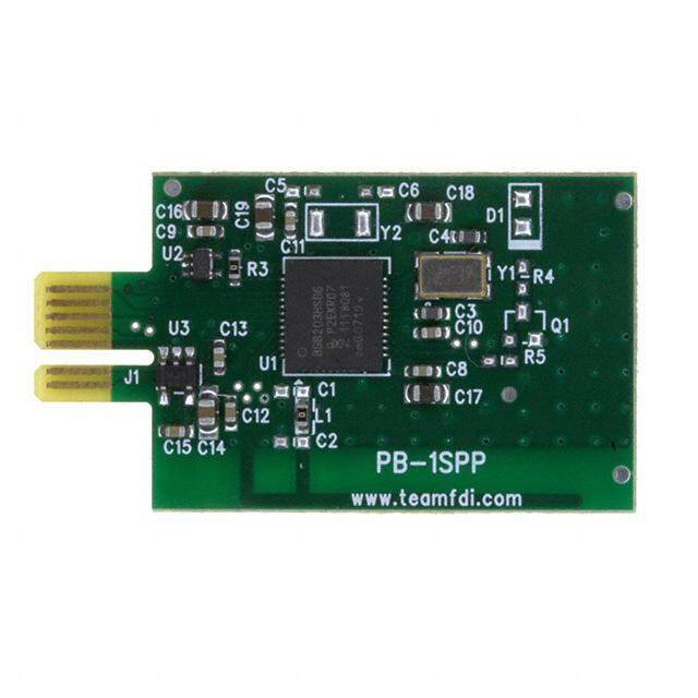
| 描述 | KIT DEMO SI4012 DISPL 434MHZ RX射频开发工具 Si4012 Kit w/LCD Si4355 RX 434MHz |
| 产品分类 | |
| 品牌 | Silicon LabsSilicon Laboratories Inc |
| 产品手册 | |
| 产品图片 | |
| rohs | 符合RoHS无铅 / 符合限制有害物质指令(RoHS)规范要求 |
| 产品系列 | 射频/无线开发工具,射频开发工具,Silicon Labs 4012-LCDK1W-434EZRadio® |
| 数据手册 | |
| 产品型号 | 4012-LCDK1W-4344012-LCDK1W-434 |
| 产品 | Development Kits |
| 产品种类 | 射频开发工具 |
| 商标 | Silicon Labs |
| 商标名 | EZRadio |
| 工作电源电压 | 1.8 V to 3.6 V |
| 工具用于评估 | Si4012, Si4355 |
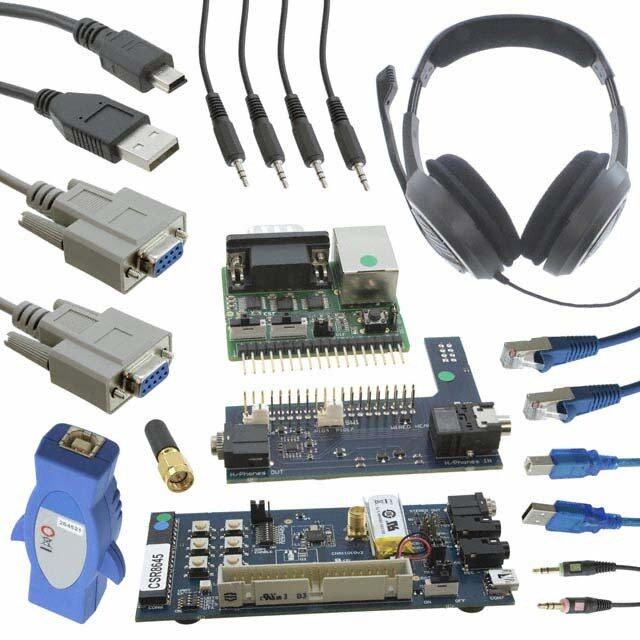
| 所含物品 | 4 个板,天线,电池,线缆 |
| 描述/功能 | 434 MHz EZRadio Si4355 one-way LCD development kit |
| 最大工作温度 | + 85 C |
| 最小工作温度 | - 40 C |
| 标准包装 | 1 |
| 用于 | Si4012, Si4355 |
| 类型 | 发射器RF Transmitters |
| 系列 | 4012-LCDK1W |
| 配套使用产品/相关产品 | Si4012 |
| 频率 | 434 MHz434MHz |




- 商务部:美国ITC正式对集成电路等产品启动337调查
- 曝三星4nm工艺存在良率问题 高通将骁龙8 Gen1或转产台积电
- 太阳诱电将投资9.5亿元在常州建新厂生产MLCC 预计2023年完工
- 英特尔发布欧洲新工厂建设计划 深化IDM 2.0 战略
- 台积电先进制程称霸业界 有大客户加持明年业绩稳了
- 达到5530亿美元!SIA预计今年全球半导体销售额将创下新高
- 英特尔拟将自动驾驶子公司Mobileye上市 估值或超500亿美元
- 三星加码芯片和SET,合并消费电子和移动部门,撤换高东真等 CEO
- 三星电子宣布重大人事变动 还合并消费电子和移动部门
- 海关总署:前11个月进口集成电路产品价值2.52万亿元 增长14.8%

PDF Datasheet 数据手册内容提取
EZRadio-DK Range Test Demo EZRADIO® Si4455 TWO-WAY AND Si4012/Si4355 ONE-WAY LINK DEVELOPMENT KIT USER’S GUIDE 1. Overview Thank you for your interest in Silicon Labs’ EZRadio® product family. The Silicon Labs EZRadio Si4455 Two-Way Link and Si4012/Si4355 EZRadio One-Way Link Development Kit (P/N EZR-LCDK2W-XXX and P/N 4012- LCDK1W-XXX) contains everything you need to familiarize yourself with and evaluate the Silicon Labs EZRadio family. The two-way kit has three versions: one for the 434MHz band, one for the 868MHz band, and one for the 915MHz band. The one-way kit has two versions: one for the 434MHz band, and one for the 915MHz band. The key features of the development kit are as follows: The baseboards have an LCD display and four LEDs to display information and four push-buttons to receive user commands. Additionally, the Silicon Labs Toolstick Base Adapter is integrated on the board to be easily connected to the PC. The RF pico board provides connection to the radio device (either Si4455 transceiver, Si4355 receiver, or Si4012 transmitter). All supported types of RF pico boards can be applied to the baseboard. The provided software pack contains all the documentation and files needed to develop a user application. The kit supports the use of the Silicon Laboratories Integrated Development Environment (IDE) for software debugging and the use of the Keil & SDCC C compiler, assembler, and linker toolchain. The kit supports use of the Wireless Development Suite (WDS) for setting radio parameters and managing application firmware. The baseboards come with the EZRadio range test demo application. The range test demo implements Packet Error Rate (PER) measurement. PER is generally used in wireless systems to measure the quality of the RF link in given circumstances. Rev. 0.2 1/13 Copyright © 2013 by Silicon Laboratories EZRadio-DK Range Test Demo
EZRadio-DK Range Test Demo 1.1. Kit Contents Table 1. Kit Contents Qty Part Number Description EZR-LCDK2W-434 Si4455 EZRadio Two-Way Link Development Kit 434MHz 2 MSC-LCDBB930-PER LCD baseboard with range test demo code 2 4455-PCE10D434B Si4455 pico board with PCB antenna and SMA connector—434MHz 2 MSC-AT50-434 434MHz antenna 2 USB-XTEN-MINI USB cable (USBA-USB mini) 6 AA AA alkaline battery EZR-LCDK2W-868 Si4455 EZRadio Two-Way Link Development Kit 868MHz 2 MSC-LCDBB930-PER LCD baseboard with range test demo code 2 4455-PCE10D868B Si4455 pico board with PCB antenna and SMA connector—868MHz 2 MSC-AT50-868 868MHz antenna 2 USB-XTEN-MINI USB cable (USBA-USB mini) 6 AA AA alkaline battery EZR-LCDK2W-915 Si4455 EZRadio Two-Way Link Development Kit 915MHz 2 MSC-LCDBB930-PER LCD baseboard with range test demo code 2 4455-PCE10D915B Si4455 pico board with PCB antenna and SMA connector—915MHz 2 MSC-AT50-915 915MHz antenna 2 USB-XTEN-MINI USB cable (USBA-USB mini) 6 AA AA alkaline battery 4012-LCDK1W-434 Si4012/Si4355 EZRadio One-Way Link Development Kit 434MHz 2 MSC-LCDBB930-PER LCD baseboard with range test demo code 1 4355-PRXBD434B Si4355 pico board with PCB antenna and SMA connector—434MHz 1 4012-PSC10B434B Si4012 pico board with PCB antenna and SMA connector—434MHz 2 MSC-AT50-434 434MHz antenna 2 USB-XTEN-MINI USB cable (USBA-USB mini) 6 AA AA alkaline battery 2 Rev. 0.2
EZRadio-DK Range Test Demo Table 1. Kit Contents (Continued) 4012-LCDK1W-915 Si4012/Si4355 EZRadio One-Way Link Development Kit 915MHz 2 MSC-LCDBB930-PER LCD baseboard with range test demo code 1 4355-PRXBD915B Si4355 pico board with PCB antenna and SMA connector—915MHz 1 4012-PSC10B915B Si4012 pico board with PCB antenna and SMA connector—915MHz 2 MSC-AT50-434 915MHz antenna 2 USB-XTEN-MINI USB cable (USBA-USB mini) 6 AA AA alkaline battery Figure 1. LCD Baseboard (P/N MSC-LCDBB930-PER) Figure 2. Si4455 RF Pico Board—868 MHz (P/N 4455-PCE10D868B) Rev. 0.2 3
EZRadio-DK Range Test Demo Figure 3. LCD Baseboard with Connected RF Pico Board The LCD baseboard is a development board that can be used with a connected RF pico board. The development board has LEDs, push-buttons, an LCD screen, and a buzzer for human interface usage. Silicon Labs Toolstick Debug Adapter is also integrated on the board to allow easy connection to the PC. The EZRadio chip is mounted on the RF pico board. Device (board and RF) information of the RFstick is stored in the on-board EEPROM. The RF pico board can be connected to the LCD baseboard with RFP1 and RFP2 connectors. For more information on using the LCD baseboard and RF pico boards to develop your own radio application, refer to the application note, “AN692: Si4x55 Programming Guide and Sample Codes” and “AN746: Si4012 Programming Guide”. The baseboards come with the EZRadio range test demo application; however, be sure to use the latest version of the application. The user can update the firmware on the boards using the firmware update functionality of the WDS. For more information on updating the firmware, refer to the "WDS User's Guide for EZRadio Next Generation". 4 Rev. 0.2
EZRadio-DK Range Test Demo 2. Range Test Demo 2.1. Basics As earlier described, the range test demo is used to provide measured results on the quality of the RF link. The demo uses two RF nodes: the LCD baseboard + RF picoboard. One node is used as the ‘transmitter’ (TX) and the other as the ‘receiver’ (RX). The Si4455 node can be either a transmitter or receiver. The Si4355 node can be only a receiver and the Si4012 node can be only a transmitter. The transmitter sends packets to the receiver repeatedly with half second intervals. The packet includes the address of the transmitter and number of the sent packet. The packet number increments from packet to packet. The receiver receives the packet and checks its address. If their addresses match, the packet number is stored. In two-way development kits, the receiver can send back an acknowledge packet (ACK) to the transmitter. The ACK packet also includes the address and packet number of the received packet. PER can be calculated with the following equation: P –P PER = -----T---X-------------R----X--100 P TX where: PER: packet error rate (%). PTX: number of sent packets. PRX: number of received packets. In two-way development kits the transmitter can calculate PER using the following data: PTX: packet counter to be included in the packet. PRX: number of all the received acknowledge packets. Receiver can calculate PER using the following data: PTX: packet number included in the last received packet. PRX: number of all received data packets. 2.2. RF and Packet Parameters This section provides information on user parameters of the range test demo. All the parameters (excluding fre- quency band and self node address) can be changed in the demo through its menu system (see section “2.4. Menu System of the Range Test Demo”). The following parameters are available: RF parameters Frequency band (defined by the HW) Communication frequency Modulation Data rate Output power Packet parameters Packet length Maximum number of sent/received packets Self node address (defined by the HW) Destination node address Demo parameters are stored in the MCU’s flash memory and restored after power-on reset. Default values are loaded if no parameters were previously stored in the flash. It is also possible to define custom RF parameters for communication. Custom parameters can be stored with the Wireless Development Suite (WDS). For more information on creating and storing custom RF parameters, refer to the “WDS User’s Guide for EZRadio Next Generation”. Rev. 0.2 5
EZRadio-DK Range Test Demo 2.2.1. Frequency and Frequency Bands The RF pico board has an on-board antenna and RF matching to provide solutions for supported frequency bands. A stand-alone antenna can also be used with the SMA connector. Different RF matchings are required for each frequency band. The range test demo automatically reads frequency band information out of the on-board EEPROM and selects the appropriate frequency range. Si4x55 devices support the following three frequency bands: Low band: 285–350MHz Middle band: 425–525MHz High band: 850–960MHz The EZRadio Development Kits are provided for the middle and the high bands; however, the range test demo supports all the three bands. The demo can be used with low band RF pico boards as well. The range test demo provides four different selectable frequencies in all the supported bands. Table2. lists the available frequencies. Table 2. Frequency Options for the EZRadio Two-Way Development Kit Low Middle High 289.28MHz 433.92MHz 867.84MHz 289.43MHz 434.15MHz 868.30MHz 305.67MHz 458.50MHz 917.00MHz 316.67MHz 475.00MHz 950.00MHz 2.2.2. Modulation User can select from three types of modulation: 2GFSK with high precision TX crystal (TX: 30ppm, RX: 30ppm)* 2FSK/2GFSK (TX: 150ppm, RX: 30ppm) * OOK *Note: 2GFSK is supported by Si4x55 devices. 2FSK is supported by Si4012 devices. 2.2.3. Data Rate The user can select from three different data rates. Table3 lists the available data rates. Table 3. Available Data Rates Modulation 2FSK/2GFSK OOK (both types) 9.6kbps 2.4kbps 38.4kbps 9.6kbps 128.0kbps* 20.0kbps *Note: Only supported by Si4x55 devices. 6 Rev. 0.2
EZRadio-DK Range Test Demo 2.2.4. Output Power The current version of the range test demo does not support changing the output power. The output power is defined for +11dB for all the frequency bands. 2.2.5. Packet Length The user can define the length of the communication packets. The packet length contains 4 bytes of preamble, 2 bytes of synch word, at least 7 bytes long payload, and 2 bytes of CRC. Increasing the packet length increases the length of the used payload. The length of the whole packet can be selected from 15 bytes to 72 bytes. 2.2.6. Maximum Number of Sent/received Packets The user can define the maximum number of sent and received packets. The demo stops after the defined number of packets received or sent. The following packet counts can be selected: 200, 500, 1000, 2000, 5000, 10000. 2.2.7. Node Addresses Each node of the range test demo reads the serial number of the connected RF pico board. The least significant byte of its serial number (0 - 255) is used as node address. The user has to define the address of the destination node in the menu system to pair the appropriate nodes. 2.2.8. Custom Parameters As described earlier, the user can store custom RF parameters into the devices with WDS. One custom field is available in each of the nodes. If custom parameter mode is selected, the RF parameters (frequency, modulation, data rate) are defined by the stored custom parameters and they cannot be changed. Note: Since custom parameters belong to a defined frequency band, the firmware goes to error state if the frequency band of the custom parameters mismatches with the frequency band of the connected RF pico board. 2.3. Error states In case of critical error, the demo goes to error state. Power-on-reset can force the demo out of error state. In error state, LED4 is continuously ON and an error message is shown on the LCD screen. Critical errors: 1. Error message: No RF pico board found! Connect an EZRadio RF pico then Reset! Cause: There is no supported RF pico connected to the LCD baseboard. Solution: Connect a supported EZRadio RF pico board (Si4x55 or Si4012) and reset the application. 2. Error message: Not supported radio! Connect a Si4x55 type RF pico then Reset! Cause: The connected RF pico board holds unsupported radio. Solution: Connect a supported EZRadio RF pico board (Si4x55 or Si4012) and reset the application. 3. Error message: Not supported custom frequency band! Custom freq band mismatches with RF pico. Cause: Frequency band of the connected RF pico board mismatches with frequency band of the stored custom parameters. Solution 1: Change custom parameters with WDS to match with the connected RF pico board. Solution 2: Change the connected RF pico board to match with the stored custom parameters. Solution 3: Use selected parameters instead of the custom parameters. Rev. 0.2 7
EZRadio-DK Range Test Demo 2.4. Menu System of the Range Test Demo After running the demo, the first screen is the Welcome Screen. The Welcome Screen is shown for up to 1.5 sec- onds or for as long as any of the push buttons are pressed. The second screen provides information on the firm- ware, covered device name, firmware name, and version number of the firmware is displayed. Figure 4. Welcome Screen Figure 5. Firmware Information The on-screen menu system is designed for easy configuration. The RF and packet parameters of the communication can be configured as described in the previous sections. Four push buttons are used to navigate the menu system: soft labels on the LCD screen display the current function of the related buttons. In general, push button 1 (PB1) is used to go to the previous menu page; push button 2 (PB2) is used to select between menu items, push button 3 (PB3) is used to change value of the menu item, and push button 4 (PB4) is used to access the next menu page. Some of the menu items have more than ten possible values. In such cases, not only PB3 can be used to increase the value of the menu item, but PB2 and PB3 can be used together to decrease its value. To decrease such values, push and hold PB2 and then push PB3 several times to reach the required value. A small arrow ( ) points to the actual menu item. The demo can be configured through six menu pages. The first page is used to select the functionality of the demo. The range test can be performed in single way (TX— transmit or RX—receive mode)* or bidirectional (TRx—transceiver mode)** radio communication. If custom RF parameters are stored, the user can choose between “Custom” or “Select” RF parameters. If “Custom” RF parameters is selected, the user can only check but not change the RF parameters on the following menu pages. Notes: 1. Si4455 devices can be both transmitters or receivers; Si4355 devices can be only receivers, and Si4012 devices can be only transmitters. 2. Bidirectional mode is only supported by Si4455 devices. Figure 6. Menu Page: System Function 1/6 8 Rev. 0.2
EZRadio-DK Range Test Demo The frequency and the modulation can be selected on the second menu page. Selectable frequency values belong to the frequency band of the RF pico board. Modulation can be “2GFSK_I”, which refers to 2GFSK with high-preci- sion TX crystal, “2GFSK_h”, which refers to 2GFSK with low cost TX clock, and “OOK”. Figure 7. Menu Page: RF Parameters 2/6 On the third menu page, only the data rate can be selected by the user. The second menu item only informs the user about deviation or bandwidth RF parameter, which depends on the selected modulation and data rate. “Deviation” is shown if the selected modulation is 2GFSK and “Bandwidth” if the modulation is OOK. Figure 8. Menu Page: RF Parameters 3/6 (Modulation is 2GFSK) Figure 9. Menu Page: RF Parameters 3/6 (Modulation is OOK) Figure 10. Menu Page: RF Parameters 4/6 (Output power is not shown in one-way receiver mode) The fifth and sixth menu page is used to configure the packet configuration of the range test demo. PB2 + PB3 button combo can be used on both pages to decrease the value of the selected menu item. Packet length and maximum number of packets can be selected according to section “2.2.5. Packet Length” and section “2.2.6. Maximum Number of Sent/received Packets”. Packet length cannot be set if RX mode operation is selected previously, since the received packet contains the length information. Rev. 0.2 9
EZRadio-DK Range Test Demo Figure 11. Menu Page: Node Parameters 5/6 (Tx/TRx mode) Figure 12. Menu Page: Node Parameters 5/6 (Rx mode) The Self ID field is filled up automatically based on the serial number of the used RF pico board. It is important to setup the destination ID accurately, otherwise the link will not work. The destination ID has to be the self ID of the other device. Figure 13. Menu Page: Node Parameters 6/6 As described earlier, demo parameters are stored in the MCU's flash memory and restored after power-on-reset. Default values are loaded if no parameters were previously stored in the flash. The default packet configuration of the demo is the following: Destination ID is the same as the Self ID Packet length is 15 bytes Max. packets is 1000 packets 10 Rev. 0.2
EZRadio-DK Range Test Demo 2.5. Test Modes 2.5.1. Bidirectional (TRx) Range Test After the demo is fully configured, it proceeds to the demo screen, where the range test can be started. The screen is divided into three sections. At the top of the screen, soft labels show the functions of the LEDs. LED1 blinks when a packet is transmitted; LED2 blinks if a packet is successfully received (with valid CRC and packet content that matches the expected value).The bar graph under LED3 shows the actual Receive Signal Strength Level (RSSI) of the received packet (shown and refreshed after a packet is received). The middle section of the screen shows the part number of the radio and the source / destination addresses with arrows showing direction of the communication. RF parameters can be checked in the middle section before transmission / reception is started. Figure 14. Demo Screen (TRx Mode) On the bottom of the screen, the soft labels show the actual functionality of the push buttons. PB3 are used to return to the configuration menu. After entering demo mode, both ends of the link are in receive mode. The test starts if any of the link nodes starts to transmit ping packets. Transmission can be initiated by pressing PB1. After that, the originator transmits a ping packet for the other node. If it receives the packet correctly, it transmits back an acknowledgment packet. Each ping packet has a serial number (increased by the originator after every packet transmission), which is transmitted back by the acknowledgment packet. If the originator receives the acknowledgment within a predefined timeout, then it considers the link working, otherwise it increases the number of missed packets by one. The originator also stores the number of transmitted PING packets so the demo can calculate the Packet Error Rate based on this information. The Packet Error Rate is updated on the third line of the LCD after each packet transmission according to PER equation in section “2.1. Basics”. Figure 15. Running PER Test (TRx Mode) The demo runs as long as the number of transmitted packets reaches the predefined number or until it is interrupted by PB1. The user can check predefined RF parameters of the measurement any time during a running test by using PB4. PB4 also is used in the info screen to show the actual results of the running measurement. Info screen is also available after all the packets are transmitted and the test is finished. Rev. 0.2 11
EZRadio-DK Range Test Demo 2.5.2. Single Way (Tx-Rx) Range Test The range test also can be performed with single way radio communication. In this case, one end of the link needs to be setup as a transmitter (this will be the originator as described in the bidirectional link) and the other end of the link needs to be a receiver. The test needs to be started at the transmit side by pressing PB1. The demo runs as long as the number of transmitted or received packets reaches the predefined number or until the demo is interrupted by PB1. The user can follow the number of transmitted packets on the LCD screen. Figure 16. Running PER Test (Tx Mode) The single way range test demo works the same as the bidirectional range test; however, the number of lost packets and the packet error rate is defined only at the receive side and is based on the first and last received packet ID. Figure 17. Running PER Test (Rx Mode) 2.6. How to Carry the Range Test Out Connect RF pico boards to the two LCD baseboards. Put batteries into the devices and switch the devices on. Select both devices to be in TRX mode or one of them to be RX and the other to be in TX mode (note that Si4355 base devices can only be receivers and Si4012 devices can only be transmitters). Select the required demo parameters or start the measurements with the automatically reloaded configuration. Check if transmitter sends packets and receiver answers as well. The range test can be performed inside a building if indoor propagation is tested. However, it is advised to perform the test outside the building, line-of-sight to get the best possible range result. If PER>1%, reset the PER on the transmitter and try to walk further in the area. Propagation conditions usually improve if the user is further distanced from a possibly shadowed area. 12 Rev. 0.2
EZRadio-DK Range Test Demo 3. Schematics The following pages contain schematics of the RFstick boards. Complete manufacturing file pack with CAD/CAM files and BOMs can be found at www.silabs.com. 1 S OF RFP112RF_MISO34RF_NSEL56RF_SDN78910RF_GPIO_11112RF_GPIO_3131415161718RFVDD1920 RFP21234567891011121314EBID_SDA15161718VPP1920 J4123456789101112131415 N LABORATORIE CE10D868B REV:1V31SHEET: D P MOSISCLKNIRQ GPIO_0GPIO_2 RFVDD EBID_SCLVPP RFVD RF_SDNRF_GPIO_3RF_GPIO_2RF_NSELRF_MOSIRF_MISORF_SCLKRF_NIRQRF_GPIO_1RF_GPIO_0 VPP SILICO 4455- 30/2012 RF_RF_RF_ RF_RF_ 15RF_MOSI14RF_MISO13RF_SCLK12RF_NIRQ11RF_GPIO_1 RF_GPIO_0 R SILICON LABS TITLE: SizeDATE:Mar/A3 c Q1 30MHz 32LE__SOONIIPP_GGFR__FFRR 67890Si445511112 23NTLE__UISXOOONIIXPPGGSDISDOSCLKNIRQGPIO_10_ODDDDINNDDPPGGGVVE 67890P1E Schemati U1 1GND2SDN3RXP4RXN5TX C5 100nF ard o ction NDS_FR C4 33pF o B RF Se CR2 1.2pF LR118nH LR2 27nH CR13.0pF RFVDD C9 68pFLC120nH C0L0 18nH3.6pF CM 5.1pFRFVDD R7 4R7 C1C2C3 100nF100pF2.2uF Figure18.RF Pic SCLSDA atching for 868MHzayer inductors LMLM2 6.8nH0R CM2CM3 5.1pFN.F. RF EBID VPP C11100nF U318A0VCC27A1WPEBID_36A2SCLEBID_45VSSSDA 24AA64T-I/MNY nna R152 0R Antenna mwith multil CC1 68pF VPP e ant 1 1 2 1 2 PCB R142 0R R180R R19N.F. TRX 1 CA 2.0pF Rev. 0.2 13
EZRadio-DK Range Test Demo n 2 erface sectio TORIES 1SHEET: OF MISORF_NSELRF_SDNSCL_GPIO_1_GPIO_3 VDD JP312 N.F. VPP MOSISCLKLCD_NSELLCD_A0to LCD SDA SCL TS_RX TS_TX MCU_C2CK MCU_C2D to USB Debug Int ON LABORA LCDBB930 REV:1V2 To RF Pico Board RFP112345678910RF1112RF1314151617181920 RFP21234567891011121314151617181920 VDD k57R.4 7k11R SILICR CON LABS MSC- DATE:Apt/04/2012 Q O_0O_2 VPP zHAT6kE08S06E17RZ.2T3 SILI TITLE: SizeA3 tic 1 MOSISCLKRF_NIRSDARF_GPIRF_GPI SCLSDA MOSISCLK 3Q ema RF_GPIO_0RF_GPIO_1RF_GPIO_2RF_GPIO_3 SDASCL SCLKMISOMOSIRF_NSELRF_NIRQRF_SDN d Sch r n C21 1uF 3231302928272625 2423222120191817 109 oa o b MCU Secti C19C20 1uF1uF U2 P0.0/VREFP0.1/AGNDP0.2/XTAL1P0.3/XTAL2P0.4/TXP0.5/RXP0.6/CNVSTRP0.7/IREF0 P1.0/AD0P1.1/AD1P1.2/AD2P1.3/AD3P1.4/AD4P1.5/AD5P1.6/AD6P1.7/AD7 XTAL3XTAL4 C8051F930 CD Base C18 1uF VDD/DC+GND/DC- DCENVBAT GND P2.0/A8P2.1/A9P2.2/A10P2.3/A11P2.4/ALEP2.5/RDP2.6/WRP2.7/C2D RST/C2CK 19.L 1uF 1uF 1uF C17 1uF 31 45 2 16151413121187 6 re u C13 C14 C15 C16 1uF C8 100pF 2rep5mPJuJ1 Fig C22100nF LCD /RST29CAP1P/CSSCL30CAP1NSIAO31CAP3PVDD2VDD28CAP2P 27VSSCAP2NVSS2 21A1V022A2V123V224V325V4C132C2VOUT EADOGM132L-5 DD C6C7 10uF100nF6.3V R02re4p.mP6FJ.RuNJ1 3940373638 3435 2633 120 219 V 31R 1 Z C23 1uF R033 deR B 1k R21 18R1/4W 4R 4DEL k1 R16 DD D R033 wolleY 3_OIPG_FR 21R 4BP DD VU VD 3R 3DEL k1 V C 2_OIPG_FR CD_NSELSCLKMOSILCD_A0 to U2 M R20R33 neerG2DEL 1_OIPG_FR 01k111RR 32BBPP L D R033 wolleY k1 VD 1R 1DEL 0_OIPG_FR 9R 1BP 14 Rev. 0.2
EZRadio-DK Range Test Demo 2 J7ONN_SMT_MINI VBUSD-D+IOGND 67 TORIES 2SHEET: OF _C12345 A 0 B US R 3 VDD 5k11R wolleY7DEL VDD R7FUSE_PTC N LABO CDBB9 REV:1V2 S GTHAB3050PS-EDOID L 4k12R deR6DEL R8 2k J8 VBU 234 1D 1 SILICO MSC- /2012 neerG5DEL VDD 1234 DD C3 100nF R ABS Apt/04 V CON L DATE: 191812111716 131415 10 9 7843 SILI TITLE: SizeA3 2 ce Section U3CF326-SX0261GM VDDP2.0P2.1P2.2VIOP2.3P2.4P2.5P0.0P0.1P0.2N/CP0.3N/CP0.4N/CP0.5P3.0/C2DP0.6P0.7C2CK/RST REGINVBUSN/CD-N/CD+GND 2 Schematic a rf 6 5 128272625242322 2021 d e USB Debug Int VDD C1C2 4.7uF100nF TDI_C2CLKTCK_C2DATTDO_C2DATPSTMS_C2CLKPS GPIO0_RTS GPIO1_CTS VDD C12C10 100nF1uF D Baseboar TS_TXTS_RX C11 100nF 0.LC to MCU section U134VINVOUT15NCEN62GNDBYP MIC5353-33YMT Figure2 k7.4 .F.N k01 VDD 02R 91R 81R VPP C9 100pF 2 14131110 987 56 JP2 N.F. C5 1uF D D 1 EBID U4 P1.0/CP0+DP1.1/CP0-P1.20/VREFP1.31/AGND2/XTAL13/XTAL2P1.54/TXP1.6/XTAL35/RXP1.7/XTAL467/IREF0C2CK/RSTP2.7/C2DDD C8051F981-GM VD U55VCC6SY114ZY023GND 74LVC1G3157GWVD U65VCC6SY114ZY023GND 74LVC1G3157GW VDD VBUS 1PSW1J123 SWITCH-SSA12G C4 1uF VD P0.P0.P0.P0.P0.P0.P0.P0. GNGN 0L 1C 4 21201918171615 312 D2R052 MB 2A AAX3_YRETTAB + - D 2 1 D V C24 100nF _C2CK U_C2D TAB U C SDASCL MC M Rev. 0.2 15
EZRadio-DK Range Test Demo DOCUMENT CHANGE LIST Revision 0.1 to Revision 0.2 Added Si4012 one-way range test demo support. Rev. 0.2 16
EZRadio-DK Range Test Demo NOTES: Rev. 0.2 17
Simplicity Studio One-click access to MCU tools, documentation, software, source code libraries & more. Available for Windows, Mac and Linux! www.silabs.com/simplicity MCU Portfolio SW/HW Quality Support and Community www.silabs.com/mcu www.silabs.com/simplicity www.silabs.com/quality community.silabs.com Disclaimer Silicon Laboratories intends to provide customers with the latest, accurate, and in-depth documentation of all peripherals and modules available for system and software implementers using or intending to use the Silicon Laboratories products. Characterization data, available modules and peripherals, memory sizes and memory addresses refer to each specific device, and "Typical" parameters provided can and do vary in different applications. Application examples described herein are for illustrative purposes only. Silicon Laboratories reserves the right to make changes without further notice and limitation to product information, specifications, and descriptions herein, and does not give warranties as to the accuracy or completeness of the included information. Silicon Laboratories shall have no liability for the consequences of use of the information supplied herein. This document does not imply or express copyright licenses granted hereunder to design or fabricate any integrated circuits. The products must not be used within any Life Support System without the specific written consent of Silicon Laboratories. A "Life Support System" is any product or system intended to support or sustain life and/or health, which, if it fails, can be reasonably expected to result in significant personal injury or death. Silicon Laboratories products are generally not intended for military applications. Silicon Laboratories products shall under no circumstances be used in weapons of mass destruction including (but not limited to) nuclear, biological or chemical weapons, or missiles capable of delivering such weapons. Trademark Information Silicon Laboratories Inc., Silicon Laboratories, Silicon Labs, SiLabs and the Silicon Labs logo, CMEMS®, EFM, EFM32, EFR, Energy Micro, Energy Micro logo and combinations thereof, "the world’s most energy friendly microcontrollers", Ember®, EZLink®, EZMac®, EZRadio®, EZRadioPRO®, DSPLL®, ISOmodem ®, Precision32®, ProSLIC®, SiPHY®, USBXpress® and others are trademarks or registered trademarks of Silicon Laboratories Inc. ARM, CORTEX, Cortex-M3 and THUMB are trademarks or registered trademarks of ARM Holdings. Keil is a registered trademark of ARM Limited. All other products or brand names mentioned herein are trademarks of their respective holders. Silicon Laboratories Inc. 400 West Cesar Chavez Austin, TX 78701 USA http://www.silabs.com
Mouser Electronics Authorized Distributor Click to View Pricing, Inventory, Delivery & Lifecycle Information: S ilicon Laboratories: 4012-LCDK1W-434
 Datasheet下载