ICGOO在线商城 > 3KP30A
 Datasheet下载
- 型号: 3KP30A
- 制造商: Littelfuse
- 库位|库存: xxxx|xxxx
- 要求:
| 数量阶梯 | 香港交货 | 国内含税 |
| +xxxx | $xxxx | ¥xxxx |
查看当月历史价格
查看今年历史价格
3KP30A产品简介:
ICGOO电子元器件商城为您提供3KP30A由Littelfuse设计生产,在icgoo商城现货销售,并且可以通过原厂、代理商等渠道进行代购。 提供3KP30A价格参考以及Littelfuse3KP30A封装/规格参数等产品信息。 你可以下载3KP30A参考资料、Datasheet数据手册功能说明书, 资料中有3KP30A详细功能的应用电路图电压和使用方法及教程。
| 参数 | 数值 |
| 品牌 | Littelfuse |
| 产品目录 | 半导体 |
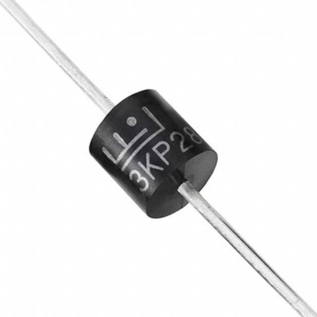
| 描述 | TVS 二极管 - 瞬态电压抑制器 TVS Diode 3KP Axial Uni-Directional |
| 产品分类 | 分离式半导体 |
| 产品手册 | |
| 产品图片 |
|
| rohs | 符合RoHS |
| 产品系列 | 二极管与整流器,TVS二极管,TVS 二极管 - 瞬态电压抑制器,Littelfuse 3KP30A |
| 产品型号 | 3KP30A |
| 产品种类 | TVS 二极管 - 瞬态电压抑制器 |
| 击穿电压 | 33.3 V |
| 商标 | Littelfuse |
| 安装风格 | Through Hole |
| 封装 | Reel |
| 封装/箱体 | P600 |
| 尺寸 | 9.1 mm Dia. x 9.1 mm L |
| 峰值浪涌电流 | 62 A |
| 峰值脉冲功率耗散 | 3 kW |
| 工作电压 | 30 V |
| 工厂包装数量 | 800 |
| 最大工作温度 | + 175 C |
| 最小工作温度 | - 55 C |
| 极性 | Unidirectional |
| 端接类型 | Axial |
| 系列 | 3KP |
| 钳位电压 | 48.4 V |


- 商务部:美国ITC正式对集成电路等产品启动337调查
- 曝三星4nm工艺存在良率问题 高通将骁龙8 Gen1或转产台积电
- 太阳诱电将投资9.5亿元在常州建新厂生产MLCC 预计2023年完工
- 英特尔发布欧洲新工厂建设计划 深化IDM 2.0 战略
- 台积电先进制程称霸业界 有大客户加持明年业绩稳了
- 达到5530亿美元!SIA预计今年全球半导体销售额将创下新高
- 英特尔拟将自动驾驶子公司Mobileye上市 估值或超500亿美元
- 三星加码芯片和SET,合并消费电子和移动部门,撤换高东真等 CEO
- 三星电子宣布重大人事变动 还合并消费电子和移动部门
- 海关总署:前11个月进口集成电路产品价值2.52万亿元 增长14.8%


PDF Datasheet 数据手册内容提取
Transient Voltage Suppression Diodes Axial Leaded – 3000W > 3KP series 3KP Series RoHS Pb e3 Description Uni-directional The 3KP Series is designed specifically to protect sensitive electronic equipment from voltage transients induced by lightning and other transient voltage events. Bi-directional Features • 3000W peak pulse • Typical I less than 2μA R capability at 10/1000μs when V min>12V BR waveform, repetition rate • High temperature (duty cycles):0.01% to reflow soldering Agency Approvals • Glass passivated chip guaranteed: 260°C/40sec junction in P600 package / 0.375”, (9.5mm) lead AGENCY AGENCY FILE NUMBER • Fast response time: length, 5 lbs., (2.3kg) E230531 typically less than 1.0ps tension from 0 Volts to BV min • V @ T= V @25°C BR J BR Maximum Ratings and Thermal Characteristics • Excellent clamping x (1+αT x (T - 25)) J (TA=25OC unless otherwise noted) capability (αT:Temperature Coefficient, typical value • Typical failure mode is Parameter Symbol Value Unit is 0.1%) short from over-specified Peak Pulse Power Dissipation by voltage or current • Plastic package is 10/1000μs Test Waveform (Fig.2) P 3000 W flammability rated V-0 per (Note 1), (Note 4) PPM • Whisker test is conducted Underwriters Laboratories based on JEDEC Steady State Power Dissipation on P 7.0 W JESD201A per its table 4a • Matte tin lead–free plated Infinite Heat Sink at T=75ºC D L and 4c • Halogen free and RoHS Peak Forward Surge Current, 8.3ms Single Half Sine Wave Unidirectional I 300 A • IEC-61000-4-2 ESD compliant FSM Only (Note 2) 30kV(Air), 30kV (Contact) • Pb-free E3 means 2nd Maximum Instantaneous Forward • ESD protection of data level interconnect is Voltage at 100A for Unidirectional V 3.5/5.0 V F lines in accordance with Pb-free and the terminal Only (Note 3) IEC 61000-4-2 finish material is tin(Sn) Operating Junction and Storage Temperature Range TJ, TSTG -55 to 175 °C • EFT protection of data (IPC/JEDEC J-STD- lines in accordance with 609A.01) Typical Thermal Resistance Junction to Lead RθJL 8.0 °C/W IEC 61000-4-4 • Low incremental surge Typical Thermal Resistance Junction to Ambient RθJA 40 °C/W resistance Notes: 1. Non-repetitive current pulse , per Fig. 4 and derated above T (initial) =25OC per Fig. 3. J Applications 2. Measured on 8.3ms single half sine wave or equivalent square wave, duty cycle=4 per minute maximum. TVS devices are ideal for the protection of I/O interfaces, 3. V < 3.5V for single die parts and V< 5.0V for stacked-die parts. F F V bus and other vulnerable circuits used in telecom, 4. The P of stacked-die parts is 4kW and please contact littelfuse for the detail CC PPM computer, industrial and consumer electronic applications. stacked-die parts. Functional Diagram Additional Infomarion Bi-directional Datasheet Resources Samples Cathode Anode Uni-directional © 2015 Littelfuse, Inc. Specifications are subject to change without notice. Revised: 11/20/15
Transient Voltage Suppression Diodes Axial Leaded – 3000W > 3KP series Electrical Characteristics (T=25°C unless otherwise noted) A Reverse Breakdown Test Maximum Maximum Maximum Agency NuPmarbt e r NuPmarbt e r VSotlatangde o Vff V(Vooltlatsg)e @ V BIR CurIre nt CVlaomltapgineg PulseP eCaukr rent LReeavkeargsee Approval (Uni) (Bi) R T T V @ I I @V (Volts) (mA) C PP I (A) R R MIN MAX (V) PP (µ A) 3KP5.0A 3KP5.0CA 5.0 6.40 7.00 50 9.2 326.1 5000 X 3KP6.0A 3KP6.0CA 6.0 6.67 7.37 50 10.3 291.3 5000 X 3KP6.5A 3KP6.5CA 6.5 7.22 7.98 50 11.2 267.9 2000 X 3KP7.0A 3KP7.0CA 7.0 7.78 8.60 50 12.0 250.0 1000 X 3KP7.5A 3KP7.5CA 7.5 8.33 9.21 5 12.9 232.6 250 X 3KP8.0A 3KP8.0CA 8.0 8.89 9.83 5 13.6 220.6 150 X 3KP8.5A 3KP8.5CA 8.5 9.44 10.40 5 14.4 208.3 50 X 3KP9.0A 3KP9.0CA 9.0 10.00 11.10 5 15.4 194.8 20 X 3KP10A 3KP10CA 10.0 11.10 12.30 5 17.0 176.5 15 X 3KP11A 3KP11CA 11.0 12.20 13.50 5 18.2 164.8 2 X 3KP12A 3KP12CA 12.0 13.30 14.70 5 19.9 150.8 2 X 3KP13A 3KP13CA 13.0 14.40 15.90 5 21.5 139.5 2 X 3KP14A 3KP14CA 14.0 15.60 17.20 5 23.2 129.3 2 X 3KP15A 3KP15CA 15.0 16.70 18.50 5 24.4 123.0 2 X 3KP16A 3KP16CA 16.0 17.80 19.70 5 26.0 115.4 2 X 3KP17A 3KP17CA 17.0 18.90 20.90 5 27.6 108.7 2 X 3KP18A 3KP18CA 18.0 20.00 22.10 5 29.2 102.7 2 X 3KP20A 3KP20CA 20.0 22.20 24.50 5 32.4 92.6 2 X 3KP22A 3KP22CA 22.0 24.40 26.90 5 35.5 84.5 2 X 3KP24A 3KP24CA 24.0 26.70 29.50 5 38.9 77.1 2 X 3KP26A 3KP26CA 26.0 28.90 31.90 5 42.1 71.3 2 X 3KP28A 3KP28CA 28.0 31.10 34.40 5 45.4 66.1 2 X 3KP30A 3KP30CA 30.0 33.30 36.80 5 48.4 62.0 2 X 3KP33A 3KP33CA 33.0 36.70 40.60 5 53.3 56.3 2 X 3KP36A 3KP36CA 36.0 40.00 44.20 5 58.1 51.6 2 X 3KP40A 3KP40CA 40.0 44.40 49.10 5 64.5 46.5 2 X 3KP43A 3KP43CA 43.0 47.80 52.80 5 69.4 43.2 2 X 3KP45A 3KP45CA 45.0 50.00 55.30 5 72.7 41.3 2 X 3KP48A 3KP48CA 48.0 53.30 58.90 5 77.4 38.8 2 X 3KP51A 3KP51CA 51.0 56.70 62.70 5 82.4 36.4 2 X 3KP54A 3KP54CA 54.0 60.00 66.30 5 87.1 34.4 2 X 3KP58A 3KP58CA 58.0 64.40 71.20 5 93.6 32.1 2 X 3KP60A 3KP60CA 60.0 66.70 73.70 5 96.8 31.0 2 X 3KP64A 3KP64CA 64.0 71.10 78.60 5 103.0 29.1 2 X 3KP70A 3KP70CA 70.0 77.80 86.00 5 113.0 26.5 2 X 3KP75A 3KP75CA 75.0 83.30 92.10 5 121.0 24.8 2 X 3KP78A 3KP78CA 78.0 86.70 95.80 5 126.0 23.8 2 X 3KP85A 3KP85CA 85.0 94.40 104.00 5 137.0 21.9 2 X 3KP90A 3KP90CA 90.0 100.00 111.00 5 146.0 20.5 2 X 3KP100A 3KP100CA 100.0 111.00 123.00 5 162.0 18.5 2 X 3KP110A 3KP110CA 110.0 122.00 135.00 5 177.0 16.9 2 X 3KP120A 3KP120CA 120.0 133.00 147.00 5 193.0 15.5 2 X 3KP130A 3KP130CA 130.0 144.00 159.00 5 209.0 14.4 2 X 3KP150A 3KP150CA 150.0 167.00 185.00 5 243.0 12.3 2 X 3KP160A 3KP160CA 160.0 178.00 197.00 5 259.0 11.6 2 X 3KP170A 3KP170CA 170.0 189.00 209.00 5 275.0 10.9 2 X 3KP180A 3KP180CA 180.0 200.00 221.00 5 289.0 10.4 2 X 3KP190A 3KP190CA 190.0 211.00 233.00 5 310.0 9.7 2 X 3KP200A 3KP200CA 200.0 222.00 246.00 5 329.2 9.1 2 X 3KP210A 3KP210CA 210.0 233.00 258.00 5 349.5 8.6 2 X 3KP220A 3KP220CA 220.0 244.00 270.00 5 371.1 8.1 2 X For parts without A , the V is ± 10% and V is 5% higher than with A parts BR C For bidirectional type having V of 10 volts and less, the I limit is double. R R © 2015 Littelfuse, Inc. Specifications are subject to change without notice. Revised: 11/20/15
Transient Voltage Suppression Diodes Axial Leaded – 3000W > 3KP series I-V Curve Characteristics Uni-directional Bi-directional Ipp IT Vc VBRVR IRVF V Vc VBRVR IR IIRT VRVBRVc V IT Ipp Ipp P Peak Pulse Power Dissipation -- Max power dissipation PPM V Stand-off Voltage -- Maximum voltage that can be applied to the TVS without operation R V Breakdown Voltage -- Maximum voltage that flows though the TVS at a specified test current (I) BR T V Clamping Voltage -- Peak voltage measured across the TVS at a specified Ippm (peak impulse current) C I Reverse Leakage Current -- Current measured at V R R V Forward Voltage Drop for Uni-directional F Ratings and Characteristic Curves (T=25°C unless otherwise noted) A Figure 1 - TVS Transients Clamping Waveform Figure 2 - Peak Pulse Power Rating Curve Voltage Transients W)100 stacked-die, 4kW k er ( at 10x1000µs, 25°C w Voltage Across TVS o P10 e or Current Current Through TVS ak Pulse Sati n1g0lxe1 d0i0e0, µ3sk, W25 °C Voltag -PeM 1 P P P TJ initial = Tamb 0.1 0.001 0.01 0.1 1 10 t-Pulse Width (ms) Time d continues on next page. © 2015 Littelfuse, Inc. Specifications are subject to change without notice. Revised: 11/20/15
Transient Voltage Suppression Diodes Axial Leaded – 3000W > 3KP series Ratings and Characteristic Curves (T=25°C unless otherwise noted) (Continued) A Figure 3 - Peak Pulse Power Derating Curve Figure 4 - Pulse Waveform 150 100 k Pulse Power (P) or Current (I)PPPPDerating in Percentage % 257505 I- Peak Pulse Current, % IPPMRSM 15000 tr=1PI0PeµPasMke cVaHIlPuaPelMf Va(lI Pu P1a2eTPac0sM usuJ / rd1=)ltrsh02eeee50nfi W °0tpnC dµioedeisdtnceh tabc( wyt.yds hW ) R teiosar. E ev5d .0eteAh%ffieon orpemfde IaPkP M a Pe 0 td 0 25 50 75 100 125 150 175 200 0 0 1.0 2.0 3.0 4.0 TJ - Initial Junction Temperature (ºC) t-Time (ms) Figure 5 - Typical Junction Capacitance Figure 6 - Typical Transient Thermal Impedance 100000 100 Uni-direc(cid:31)onal V=0V W) C/ 10000 Bi-direc(cid:31)onal V=0V e (° c an 10 F) 1000 Uni-direc(cid:31)onal V=VR mped Cj(p Bi-direc(cid:31)onal V=VR mal I 100 er Th 1 nt e 10 nsi a Tr 0.1 1 1 10 100 1000 0.01 0.1 1 10 100 1000 VBR-Reverse Breakdown Voltage(V) TP-Pulse Duration (s) Figure 7 - Maximum Non-Repetitive Peak Forward Figure 8 - Peak Forward Voltage Drop vs Peak Forward Surge Current Uni-Directional Only Current (Typical Values) 500 450 100 Single die A) nt ( 400 A) Curre 350 ent( Surve 300 Curr 10 Stack-die ward 250 ard Peak For 125000 k Forw 1 - a M 100 e IFS 50 -PF0.1 I 0 1 10 100 0.01 Number of Cycles at 60 Hz 0.00 1.00 2.00 3.00 4.00 5.00 6.00 7.00 8.00 VF-Peak Forward Voltage(V) © 2015 Littelfuse, Inc. Specifications are subject to change without notice. Revised: 11/20/15
Transient Voltage Suppression Diodes Axial Leaded – 3000W > 3KP series Soldering Parameters Lead–free Reflow Condition assembly TP tp - Temperature Min (T ) 150°C Ramp-up Critical Zone Pre Heat - Temperature Max (Tss(m(mina)x)) 200°C T) TL tL TL to TP - Time (min to max) (t) 60 – 180 secs (e Ts(max) s ur Atov epreaagke ramp up rate (Liquidus Temp (TA) 3°C/second max TemperatTs(min) Prethseat Ramp-down T to T - Ramp-up Rate 3°C/second max S(max) A - Temperature (T ) (Liquidus) 217°C 25˚C Reflow A t 25˚C to Peak Time (t) - Time (min to max) (t) 60 – 150 seconds s Peak Temperature (T) 260+0/-5 °C P Time within 5°C of actual peak Flow/Wave Soldering (Solder Dipping) 20 – 40 seconds Temperature (t) p Ramp-down Rate 6°C/second max Peak Temperature : 265OC Time 25°C to peak Temperature (T) 8 minutes Max. Dipping Time : 10 seconds P Do not exceed 260°C Soldering : 1 time Physical Specifications Environmental Specifications Weight 0.07oz., 2.1g High Temp. Storage JESD22-A103 P600 molded plastic body over Case passivated junction. HTRB JESD22-A108 Color band denotes the cathode except Polarity Temperature Cycling JESD22-A104 Bipolar. Matte Tin axial leads, solderable per H3TRB JESD22-A101 Terminal JESD22-B102. RSH JESD22-B106 Dimensions Inches Millimeters Cathode Band Dimensions Min Max Min Max (for Uni-directional products only) D A 1.000 - 25.40 - C B 0.340 0.360 8.60 9.10 C 0.048 0.052 1.22 1.32 A B A D 0.340 0.360 8.60 9.10 P600 © 2015 Littelfuse, Inc. Specifications are subject to change without notice. Revised: 11/20/15
Transient Voltage Suppression Diodes Axial Leaded – 3000W > 3KP series Part Numbering System Part Marking System 3KPxxxXXX OPTION CODE: BLANK Reel Tape Cathode Band -B Bulk Packaging (for Uni-directional FYYWW TYPE CODE: products only) CAA BUin-Di-Direircetciotinoanla (l5 (%5% V VBVRo Vlotaltgaeg eTo Tloelrearnacnec)e) Littelfuse Logo T YrYa:cYee aCr oCoddee Marking BR WW: Week Code 3KPXXX V VOLTAGE R Product Type SERIES CODE Packing Options Component Packaging Part Number Quantity Packaging Specification Package Option 3KPxxxXX P600 800 Tape & Reel EIA STD RS-296 3KPxxxXX-B P600 100 BULK Littelfuse Spec. Tape and Reel Specification Off Center (625.5.06) either side 2.0(5633.+00+.20.709//--10..00)39 0.028(0.7) 0.047 0.236 (1.2) (6.0) 0.394+/-0.020 (10.0+/-0.5) Dimensions are in 13.0 inches/mm (330.2) 3.0 (76.2) 0.68 (17.27) 2.75 (69.85) Direction of Feed Recess Depth Max. 0.75 (19.05) © 2015 Littelfuse, Inc. Specifications are subject to change without notice. Revised: 11/20/15