ICGOO在线商城 > 35LSW47000MNB51X98
- 型号: 35LSW47000MNB51X98
- 制造商: RUBYCON
- 库位|库存: xxxx|xxxx
- 要求:
| 数量阶梯 | 香港交货 | 国内含税 |
| +xxxx | $xxxx | ¥xxxx |
查看当月历史价格
查看今年历史价格
35LSW47000MNB51X98产品简介:
ICGOO电子元器件商城为您提供35LSW47000MNB51X98由RUBYCON设计生产,在icgoo商城现货销售,并且可以通过原厂、代理商等渠道进行代购。 提供35LSW47000MNB51X98价格参考以及RUBYCON35LSW47000MNB51X98封装/规格参数等产品信息。 你可以下载35LSW47000MNB51X98参考资料、Datasheet数据手册功能说明书, 资料中有35LSW47000MNB51X98详细功能的应用电路图电压和使用方法及教程。
| 参数 | 数值 |
| 产品目录 | |
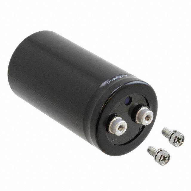
| 描述 | CAP ALUM 47000UF 35V 20% SCREW |
| ESR(等效串联电阻) | - |
| 产品分类 | |
| 品牌 | Rubycon |
| 数据手册 | |
| 产品图片 | |
| 产品型号 | 35LSW47000MNB51X98 |
| rohs | 无铅 / 符合限制有害物质指令(RoHS)规范要求 |
| 产品系列 | LSW |
| 不同温度时的使用寿命 | 105°C 时为 3000 小时 |
| 其它名称 | 35LSW47000MEFC51X98 |
| 包装 | 散装 |
| 大小/尺寸 | 2.008" 直径(51.00mm) |
| 安装类型 | 底座安装 |
| 容差 | ±20% |
| 封装/外壳 | 径向,Can - 螺丝端子 |
| 工作温度 | -40°C ~ 105°C |
| 应用 | 通用 |
| 引线间距 | 0.858" (21.80mm) |
| 标准包装 | 10 |
| 电容 | 47000µF |
| 类型 | - |
| 纹波电流 | 9.9A |
| 表面贴装焊盘尺寸 | - |
| 阻抗 | - |
| 额定电压 | 35V |
| 高度-安装(最大值) | 3.976"(101.00mm) |



- 商务部:美国ITC正式对集成电路等产品启动337调查
- 曝三星4nm工艺存在良率问题 高通将骁龙8 Gen1或转产台积电
- 太阳诱电将投资9.5亿元在常州建新厂生产MLCC 预计2023年完工
- 英特尔发布欧洲新工厂建设计划 深化IDM 2.0 战略
- 台积电先进制程称霸业界 有大客户加持明年业绩稳了
- 达到5530亿美元!SIA预计今年全球半导体销售额将创下新高
- 英特尔拟将自动驾驶子公司Mobileye上市 估值或超500亿美元
- 三星加码芯片和SET,合并消费电子和移动部门,撤换高东真等 CEO
- 三星电子宣布重大人事变动 还合并消费电子和移动部门
- 海关总署:前11个月进口集成电路产品价值2.52万亿元 增长14.8%

PDF Datasheet 数据手册内容提取
SCREW TERMINAL ALUMINUM ELECTROLYTIC CAPACITORS LSW LSW SERIES Load Life : 105℃ 3000 hours RoHS compliance ◆SPECIFICATIONS Items Characteristics Category Temperature Range −40〜+105℃ −25〜+105℃ Rated Voltage Range 10〜100Vdc 160〜400Vdc Capacitance Tolerance ±20%(20℃,120Hz) I=0.02CV or 5mA whichever is smaller. (After 5 minutes application of rated voltage) Leakage Current(MAX) I=Leakage Current(μA) C=Capacitance(μF) V=Rated Voltage(Vdc) Vdc φD 36 51 64 77 90 Vdc φD 36 51 64 77 90 (20℃, ) 10 0.75 1.0 1.3 1.5 1.5 63 0.2 0.25 0.3 0.4 0.4 120Hz Dissipation Factor(MAX) 16 0.6 0.7 0.8 1.0 1.0 80 0.2 0.2 0.25 0.3 0.3 (tanδ) 25 0.4 0.5 0.7 0.8 0.8 100 0.15 0.2 0.25 0.25 0.25 35 0.3 0.5 0.6 0.7 0.7 160〜250 0.15 0.15 0.2 0.2 0.2 50 0.25 0.3 0.5 0.6 0.6 315〜400 0.2 0.2 0.25 0.25 0.25 After applying rated voltage with rated ripple current for 3000 hours at 105℃, the capacitors shall meet the following requirements. Capacitance Change Within ±15% of the initial value. Endurance Dissipation Factor Not more than 175% of the specified value. Leakage Current Not more than the specified value. After storage for 500 hours with no voltage applied at 105℃, the capacitors shall be subjected to the voltage treatment in JIS C 5101-4 item 4.1 and shall be meet the following requirements. Shelf Life Capacitance Change Within ±15% of the initial value. Dissipation Factor Not more than 150% of the specified value. Leakage Current Not more than the specified value. ◆MULTIPLIER FOR RIPPLE CURRENT Frequenc(y Hz) 60(50)120(100) 300 500 10k≦ 10〜50Vdc 0.80 1.00 1.03 1.04 1.08 Coefficient 63〜100Vdc 0.80 1.00 1.04 1.05 1.10 160〜400Vdc 0.80 1.00 1.06 1.10 1.18 ◆PART NUMBER □□□ LSW □□□□□ M □□□ □□ D×L Rated Voltage Series Capacitance Capacitance Tolerance Option Clamp Code Case Size ◆DIMENSIONS (mm) 〈I type〉 Clamp 〈Y type〉 CBolaltmp φD W1 W2 W3 W4 W5 F Plate±2MCloaumnptingSleeveCase TSecrrmewinal Bolt W2±2 BoltW4 W3 W1±2VenPtlate±2MCloaumnptingSleeve Case TSecrrmewinal BoltVent W3W5W4 W1±2W2±2 I type5679314706 3445240744.....00000 4456305300.....00000 34443.....55555 67667.....00000 1111122240 2233118112.....82447 D F±1 D F±1 51 32.5 37.5 4.5 6.0 12 21.8 pe64 38.0 43.0 4.5 8.0 14 28.2 L±3 W5 M5 P=0.8Bolt L±3 M5 P=0.8Bolt Y ty77 44.5 49.0 4.5 7.0 14 31.4 90 50.8 56.0 4.5 8.0 16 31.4
SCREW TERMINAL ALUMINUM ELECTROLYTIC CAPACITORS LSW ◆STANDARD SIZE Vdc 10 16 25 35 50 63 80 Cap(μF) 3300 36×50 3.0 3900 36×63 3.3 4700 36×50 3.2 36×83 3.6 5600 36×63 3.5 36×83 3.9 6800 36×50 2.5 36×50 3.6 36×63 3.8 36×83 4.3 8200 36×50 2.8 36×63 3.9 36×83 4.3 36×98 5.1 10000 36×50 3.8 36×83 4.2 36×83 4.7 36×118 5.8 12000 36×63 4.3 36×83 5.0 36×98 5.6 51×83 7.0 15000 36×50 4.2 36×83 4.7 36×98 5.5 36×118 6.4 51×83 7.6 18000 36×63 4.6 36×83 5.1 36×98 5.7 51×83 7.5 51×98 7.7 22000 36×50 4.0 36×83 5.2 36×98 6.6 36×118 7.5 51×83 7.5 51×118 9.0 27000 36×50 4.4 36×63 5.0 36×83 5.4 36×118 6.7 51×83 7.5 51×98 8.7 64×99 10.1 33000 36×63 5.5 36×83 5.2 36×98 6.5 51×83 7.1 51×98 9.3 51×118 10.3 64×119 11.6 39000 36×63 6.0 36×83 5.8 36×98 7.5 51×83 8.4 51×98 9.4 64×99 11.2 64×139 13.5 47000 36×83 6.6 36×98 6.8 36×118 8.9 51×98 9.9 51×118 11.7 64×119 12.9 77×101 15.8 56000 36×83 7.5 36×98 6.9 51×83 10.0 51×98 10.3 64×99 12.4 64×139 15.2 77×121 17.0 68000 36×98 7.6 36×118 8.4 51×98 10.7 51×118 11.4 64×119 15.1 77×101 16.0 77×141 20.4 82000 36×118 9.0 51×83 8.4 51×98 12.0 64×99 12.5 77×101 15.5 77×121 17.7 77×151 21.5 100000 51×83 10.2 51×98 11.3 51×118 13.1 64×119 15.5 77×101 16.3 77×141 21.5 90×151 22.3 120000 51×83 11.0 51×98 11.4 64×99 13.7 77×101 15.5 77×121 19.1 90×141 22.4 150000 51×98 13.4 51×118 12.5 64×119 16.4 77×121 17.9 77×141 23.4 180000 51×118 14.0 64×99 14.2 77×101 16.7 77×141 20.0 90×141 23.7 220000 64×99 14.5 64×119 16.6 77×121 20.5 77×151 24.1 270000 64×119 16.0 77×101 17.5 77×141 21.3 90×141 26.5 330000 77×101 18.0 77×121 24.3 77×151 26.0 390000 77×101 19.5 77×141 25.2 90×141 27.2 470000 77×121 20.0 77×151 26.7 560000 77×141 24.1 90×141 29.1 680000 90×141 26.5 Vdc 100 160 200 250 315 350 400 Cap(μF) 220 36×50 0.9 36×50 1.0 270 36×50 1.0 36×50 1.0 36×63 1.0 330 36×50 1.2 36×63 1.2 36×63 1.2 390 36×63 1.3 36×83 1.3 36×83 1.4 470 36×50 1.3 36×83 1.5 36×83 1.5 36×98 1.5 560 36×50 1.4 36×63 1.6 36×83 1.6 36×98 1.7 36×98 1.7 680 36×50 1.5 36×83 1.7 36×98 1.9 36×98 1.9 51×83 2.3 820 36×50 1.4 36×83 1.9 36×83 1.9 36×118 2.2 36×118 2.1 51×98 2.4 1000 36×63 1.9 36×83 2.2 36×98 2.3 51×83 2.3 51×98 2.5 51×118 2.7 1200 36×83 2.3 36×83 2.3 36×98 2.4 51×98 2.7 51×98 2.7 51×118 3.0 1500 36×83 2.6 36×98 2.9 36×118 2.9 51×98 3.1 51×118 3.3 64×99 3.5 1800 36×83 2.6 36×98 2.9 36×118 3.0 51×118 3.6 64×99 3.8 64×119 3.6 2200 36×50 2.9 36×98 3.2 36×118 3.3 51×98 3.8 64×99 4.2 64×119 4.6 77×101 4.1 2700 36×63 3.4 36×118 3.2 51×83 3.8 51×118 4.5 64×119 4.3 77×101 4.6 77×121 4.8 3300 36×83 3.9 36×118 3.7 51×98 4.7 64×99 5.2 77×101 4.9 77×121 5.3 77×141 5.7 3900 36×83 4.2 51×98 4.3 51×118 5.4 64×119 5.2 77×121 5.8 77×141 6.2 90×141 6.7 4700 36×83 4.6 51×98 4.8 64×99 6.2 64×119 5.7 77×121 6.3 90×141 7.4 90×141 7.4 5600 36×98 4.9 51×118 5.5 64×99 6.3 77×101 6.4 77×141 7.3 90×141 8.1 6800 36×118 5.5 64×99 6.3 64×119 7.3 77×121 7.6 90×141 8.9 8200 51×83 6.2 64×119 7.1 77×101 8.5 77×141 8.3 10000 51×98 6.7 77×101 7.9 77×121 9.5 90×141 9.9 12000 51×98 7.3 77×121 9.0 77×141 10.5 90×141 10.8 15000 51×118 8.6 77×141 11.3 90×141 12.5 18000 64×99 8.9 90×141 13.0 90×141 13.3 22000 64×119 10.3 90×141 14.3 27000 64×139 12.1 33000 77×121 14.1 39000 77×141 16.5 47000 77×141 18.3 56000 90×141 19.2 68000 90×151 20.1 Ripple Current (A r.m.s./120Hz, 105℃) Case Size φD×L(mm) ◆Tightening torque of bolt and Permissible current of terminal Clamp Bolt Recommended Tightening torque Recommended Tightening torque Permissible Current Terminal (Permissible Range) of Terminal M3 0.6 [N・m] M5 2.2(1.5〜3.2) [N・m] 60[A r.m.s.] M4 1.3 [N・m]
 Datasheet下载
