ICGOO在线商城 > 3-1393253-7
- 型号: 3-1393253-7
- 制造商: CORCOM/TYCO ELECTRONICS
- 库位|库存: xxxx|xxxx
- 要求:
| 数量阶梯 | 香港交货 | 国内含税 |
| +xxxx | $xxxx | ¥xxxx |
查看当月历史价格
查看今年历史价格
3-1393253-7产品简介:
ICGOO电子元器件商城为您提供3-1393253-7由CORCOM/TYCO ELECTRONICS设计生产,在icgoo商城现货销售,并且可以通过原厂、代理商等渠道进行代购。 提供3-1393253-7价格参考以及CORCOM/TYCO ELECTRONICS3-1393253-7封装/规格参数等产品信息。 你可以下载3-1393253-7参考资料、Datasheet数据手册功能说明书, 资料中有3-1393253-7详细功能的应用电路图电压和使用方法及教程。
| 参数 | 数值 |
| 3D型号 | http://www.te.com/commerce/DocumentDelivery/DDEController?Action=srchrtrv&DocNm=3-1393253-7&DocType=Customer+View+Model&DocLang=English |
| 产品目录 | |
| 描述 | CIR BRKR MAG-HYDR 30A 277VAC |
| 产品分类 | |
| 品牌 | TE Connectivity |
| 数据手册 | http://www.te.com/commerce/DocumentDelivery/DDEController?Action=srchrtrv&DocNm=1308242_w6w9&DocType=DS&DocLang=EN |
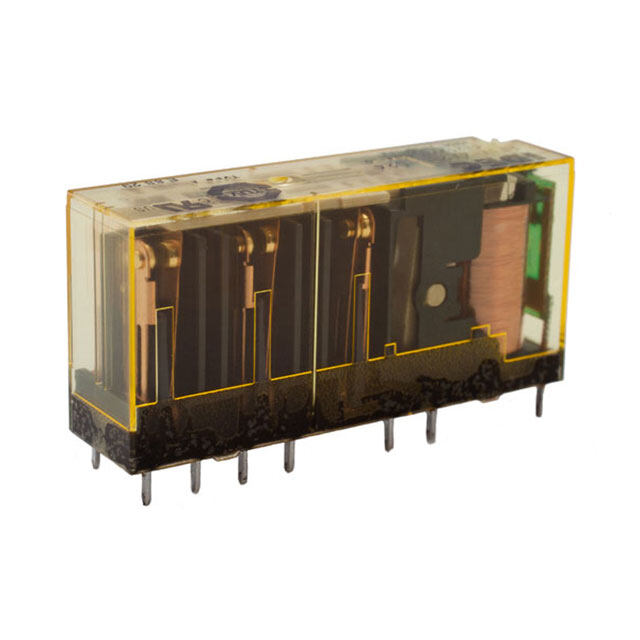
| 产品图片 |
|
| 产品型号 | 3-1393253-7 |
| rohs | 无铅 / 符合限制有害物质指令(RoHS)规范要求 |
| 产品系列 | W6,Potter & Brumfield |
| 产品培训模块 | http://www.digikey.cn/PTM/IndividualPTM.page?site=cn&lang=zhs&ptm=6307 |
| 产品目录绘图 |
|
| 产品目录页面 | |
| 其它名称 | 313932537 |
| 安装类型 | 面板安装 |
| 断路器类型 | 磁性(液力延迟) |
| 极数 | 2 |
| 标准包装 | 12 |
| 照明 | - |
| 照明电压(标称值) | - |
| 特色产品 | http://www.digikey.com/product-highlights/cn/zh/te-connectivity-circuit-breakers/3831 |
| 相关产品 | /product-detail/zh/C1113%2F42/335-1029-ND/1995320 |
| 致动器类型 | 按片 |
| 额定电压-AC | 277V |
| 额定电压-DC | - |
| 额定电流 | 30A |




- 商务部:美国ITC正式对集成电路等产品启动337调查
- 曝三星4nm工艺存在良率问题 高通将骁龙8 Gen1或转产台积电
- 太阳诱电将投资9.5亿元在常州建新厂生产MLCC 预计2023年完工
- 英特尔发布欧洲新工厂建设计划 深化IDM 2.0 战略
- 台积电先进制程称霸业界 有大客户加持明年业绩稳了
- 达到5530亿美元!SIA预计今年全球半导体销售额将创下新高
- 英特尔拟将自动驾驶子公司Mobileye上市 估值或超500亿美元
- 三星加码芯片和SET,合并消费电子和移动部门,撤换高东真等 CEO
- 三星电子宣布重大人事变动 还合并消费电子和移动部门
- 海关总署:前11个月进口集成电路产品价值2.52万亿元 增长14.8%
PDF Datasheet 数据手册内容提取
General Purpose Relays Industrial Relays Potter & Brumfield W6/W9 Series Magnetic Hydraulic P&B Circuit Breakers n Designed for the international market. UL Recognzied (UL1077 and UL1500), CSA Accepted and VDE approved. n Ratings to 50 amps. n Heavy duty #10-32 stud connections. (W9) n Quick-connect or screw terminals. (W6) n Several delay curve options. n Trip-free operation. Agency Approvals UL: Recognized as Supplementary Protector under UL 1077. Available Mechanical/Environmental Data (continued) models meet Ignition Protection requirements in accordance with Fungus and Moisture Resistance: UL1500. File E69543 Special moisture resistant finish applied to all ferrous parts. CSA: Accepted as a Supplementary Protector. File LR15734. Plastic parts are made of inherently fungus resistant material. VDE: Approved to VDE 0642/EN 60 934 (Circuit Breakers for Equipment) Marking: License No. 73782 International “1” and “0” symbols are marked on the toggle for both W6 and Users should thoroughly review the technical data before selecting a product part number. W9. W9 units have “ON” and “OFF” molded into the area at the base of the It is recommended that users also seek out the pertinent approvals files of the agencies/ toggle. laboratories and review them to confirm the product meets the requirements for a given Mounting: application. Units are mounted with two #6-32 screws from the front of the panel. Metric models for use with M3 x 0.5 screws are available. To maintain Electrical Data published performance specifications, units should not be mounted more Calibration: than 90° from their normal upright position. Breakers will hold 100% of rated current. Weight: Approximately 2.5 ounces per pole. Breakers may trip between 101% and 124% of rated load (134% for AC/ DC units). Breakers must trip at 125% of rated load and above (135% for AC/DC Approvals and Ratings Table 1 units). Dielectric Strength: 50/60 Hz., 1500V: DC, 1100V Insulation Resistance: 100 Megaohms at 500VDC W6 Series UL1077/CSA (All Circuit Functions) Endurance: Current Interrupting 10,000 on/off cycles - 6000 at rated load, 4000 at no load. Maximum Frequency Phase Rating Capacity Units tested at six cycles per minute, 1 second on and 9 seconds off at Voltage (Hz) (Amps) (Amps) 25°C ambient. 65 DC - 0.2 - 50 2,000 Typical Resistance and Impedance 277 50/60 1 0.2 - 20 5,000 Current DC 50/60 277 50/60 1 21 - 50 2,500 (Amps.) Resistance Impedance 277/480 50/60 3Ø-Wye 0.2 - 20 5,000 (Ohms) (Ohms) 0.2 90 90 W9 Series UL1077/CSA (All Circuit Functions) 1.0 1.2 1.2 Current Interrupting 2.0 0.28 0.28 Maximum Frequency Phase Rating Capacity 5.0 0.04 0.04 Voltage (Hz) (Amps) (Amps) 10.0 0.013 0.013 65 DC - 0.2 - 50 2,000 20.0 0.004 0.005 277 50/60 1 0.2 - 50 5,000 30.0 0.0027 0.004 277/480 50/60 3Ø-Wye 0.2 - 20 5,000 40.0 0.002 0.002 50.0 0.0015 0.0015 W6 or W9 Series VDE (Circuit Function X) Tolerance: 0.1 - 4.99 ± 15%; 5 - 9.99 ± 20%; 10 - 15 ± 25%; 16 - 30 ± 50%. Current Interrupting Maximum Frequency Phase Rating Capacity Voltage (Hz) Mechanical/Environmental Data (Amps) (Amps) Operating Temperature: -40°C to +85°C. 65 DC - 0.2 - 50 2,000 Humidity: Meets requirements of Mil-STD-202 method 103. 250 50/60 1 0.2 - 30 5,000 Shock: Tested per Mil-STD-202, method 213, test condition C 250 50/60 1 31 - 50 2,000 (100g @ 6 ms) 415/240 50/60 3Ø 0.2 - 30 5,000 Vibration: Tested per Mil-STD-202, method 201, 10-55 Hz., 0.06” (1.52mm) total excursion in 2 planes. W6 or W9 Series UL1500 (Circuit Function X) Current Interrupting Maximum Frequency Phase Rating Capacity Voltage (Hz) (Amps) (Amps) 48 DC - 0.2 - 50 3,000 125/250 50/60 1 0.2 - 50 1,000 250 50/60 3Ø-Wye 0.2 - 50 1,000 1 11-2015, Rev. 1115 Datasheets and product specification Datasheets and product data is subject to the Datasheets, product data, ‘Definitions’ sec- www.te.com according to IEC 61810-1 and to be used terms of the disclaimer and all chapters of tion, application notes and all specifications © 2014 Tyco Electronics Corporation, only together with the ‘Definitions’ section. the ‘Definitions’ section, available at are subject to change. a TE Connectivity Ltd. company http://relays.te.com/definitions
General Purpose Relays Industrial Relays Potter & Brumfield W6/W9 Series Magnetic Hydraulic P&B Circuit Breakers (Continued) Time vs Current Trip Curves For W6 Series and W9 Series AC 50/60 Hz. 10,040000 Hz. DCC &U 5R0/V60E H 0z. INSTANTANEOTURISP TIMES 10,000 CURVE 2 STAND ARD DELAY 50/60 Hz. 10,000 CURVE 3 SHORT DELAOYV E5R0LO/6AD0 H TRzI.P TIMES TIME IN SECONDS101001.01001 OV E861142R250000L500000O%%%%%%A D @ 1 05111350522500 /mmmmmm60ssssss Hmmmmmmz.a aaaaa&xxxxxx. ..... D C 1 0 1113@M02250 a 4mmmmmy0 0ssssTs r Hmmmmimpzaaaaa.xxxxx..... TIME IN SECONDS101001.00011 O V 1 E 012468 R 02 0000 L 500000 O %%%%%% A D T R . . I 0 0P 2 .(10 00 TS..052237IE M ------C 1E.2.2..1075)0S5450 TIME IN SECONDS101001.01001 1 012468 02 0000 50 0000 %%%%%% . .. 0 00( ..S1 0000 E513373C ------ . )11....10.20555458 .01 .01 .01 .0010 110205 125000 300 4L0O0A D O 5CF0U 0BR R R E6EA0NK0T E AR 7 S0R 0AA T P IN8E0RG0C E N9T00 1000 1100 1200 .0010 112050 125000 300 4L0O0A D O 5CF0U 0BR R R E6EA0NK0T E AR 7 S0R 0AA T P IN8E0RG0C E N9T00 1000 1100 1200 .0010 112050 125000 300 4L0O0A D O 5CF0U 0BR R R E6EA0NK0T E AR 7 S0R 0AA T P IN8E0RG0C E N9T00 1000 1100 1200 MOTOR START / LONG DELAY 10,000 CURVE 10 HIGH INRUSOHV E5R0L/O6A0D H TzR. IPA TCIMES 10,000 CURVE 12 HIGH INROUVESRHLO A5D0 / 6 T0R IPH zTI.MES 10,000 CURVE 13 HIGH INROUVESRHLO A5D 0 / 6 T0R IPH zTI.MES TIME IN SECONDS101001.10001 1 246801 200000 500000 %%%%% % . 0 0 4 ..9(10928S --E---- 24C5112.0000.5)00 TIME IN SECONDS101001.10001 1 0 012468 020000 %50000 % %%%% . 0 . 0 0 1 9 . 511 50 - . - 35 -- . .3-- 1175 5 220 5. 5 (TIME IN SECONDSS1E01C001.100.01) 1 0 012468 020000 %5 0000 % %%%% . 0 . 0 0 9...0 1 009 5.-32 8 - - .-- -0 .21 9...21 3355 0 (SEC.) .01 .01 .01 .0010 112050 125000 300 4L0O0A D O 5CF0U 0BR R R E6EA0NK0T E AR 7 S0R 0AA T P IN8E0RG0C E N9T00 1000 1100 1200 .0001 112050 125000 30LO0A D O CF4U 0RB0RR EEN ATK E5AR0S 0 R AA TP IE6NRG0C0E N T 700 800 900 1000 110.00 00 11201102050 125000 30LO0A D O CF4U 0RB0RR EEN ATK E5AR0S 0 R AA TP IE6NRG0C0E N T 700 800 900 1000 1100 1200 DC CURVE 2 STANDARD DELAY DC CURVE 3 SHORT DELAY DC 101,000000 O V E R L O A D T R I P ( TSIEMCE.)S 101,000000 O V E R L O A D T R I(PS TEICM.)ES 10,000 CURVE 53 DC HIGO HV E R IL NO A RD U S H T R I P T I M E S (SEC.) TIME IN SECONDS101.0101 1 012468020000500000%%%%%% . . 0 0 . . 06 00 .124024 ------ 15..8.050.55255 TIME IN SECONDS101.0011 1 012468020000500000%%%%%% . . 0 0 ...1 0000.616334 ------ 1.7...10.20531555 TIME IN SECONDS101001.10001 10 012468020000%50000 %%%%% . 0 ..1181 70 05 0 - 2 - -- - . - 1371 15002000 .01 .01 .01 .0010 112050 125000 300 4L0O0A D O 5CF0U 0BR R R E6EA0NK0T E AR 7 S0R 0AA T P IN8E0RG0C E N9T00 1000 1100 1200 .0010 110250 125000 300 4L0O0A D O 5CF0U 0BR R R E6EA0NK0T E AR 7 S0R 0AA T P IN8E0RG0C E N9T00 1000 1100 1200 .0001 112050 125000 30LO0A D C4U0R0R EN T 5A0S0 A P E6R0C0E N T 700 800 900 1000 1100 1200 OF BREAKER RATING AC/DC CURVE 34 DC, 50/60 Hz. STANDARD DELAY 10,000 OVERLOAD TRIP TIMES 1000 (SEC.) 135% 1 - 90 TIME IN SECONDS101.1001 10 0246800000%0000 %%%% . 0 . .0 0 02.9.0 6502-0 2 - -.- - 0 2 .92.40955 .01 .001 0 112050 125000 30LO0A D C4U0R0R EN T 5A0S0 A P E6R0C0E N T 700 800 900 1000 1100 1200 135 OF BREAKER RATING Note: For instantaneous curves for all voltages refer to Curve 0 instananeous under the AC 50/60 Hz. heading 2 11-2015, Rev. 1115 Datasheets and product specification Datasheets and product data is subject to the Datasheets, product data, ‘Definitions’ sec- www.te.com according to IEC 61810-1 and to be used terms of the disclaimer and all chapters of tion, application notes and all specifications © 2014 Tyco Electronics Corporation, only together with the ‘Definitions’ section. the ‘Definitions’ section, available at are subject to change. a TE Connectivity Ltd. company http://relays.te.com/definitions
General Purpose Relays Industrial Relays PPootttteerr && BBrruummfifieelldd W6/W9 Series Magnetic Hydraulic P&B Circuit Breakers (Continued) Product code structure Typical product code W 67- X 2 Q 1 2- 20 W6 Series Circuit Breaker Mounting W #6-32 mounting threads M M3.0 x 0.5 mounting threads Number of Poles 67 Single Pole 68 Two Pole 69 Three Pole 70 Four Pole Circuit Function (Only X is VDE approved) X Series trip Actuator One actuator per pole 1 Black toggle 9 Red toggle 2 White toggle One actuator per unit 7 Black toggle 8 White toggle Termination Q .250“ QC (DIN 46 244) [30A Max. UL/CSA; 25A Max. VDE] S #8-32 screw [30A Max.] T #10-32 screw [50A Max.] U #8-32 screw, nickel plated, bent inward 30° [30A Max.] V #10-32 screw, nickel plated, bent inward 30° [30A Max.] Notes: #10-32 termination must be used for all ratings of greater than 30 amps. #10-32 termination must be specified for circuit function D, but relay trip pole will be equipped with .250“ QC. Maximum Line Voltage (see Table 1 for current ranges) UL/CSA 1 277VAC, 50/60 Hz. Types 2 277/480VAC, 50/60 Hz. [20A Max.] (Requires insulating barriers, see outline dimension drawing) 5 65VDC 7 AC/DC 277VAC, 50/60 Hz. or 65VDC (Time delay curve 34 must be specified) 8 AC/DC 120VAC, 120/240VAC, 48VDC (Agency Approval M [UL1500] and time delay curve 34 must be specified) VDE 1 250VAC, 415/240VAC Types 5 65VDC 7 AC/DC 250VAC, 415/240VAC, 65VDC (Time delay curve 34 must be specified) Time Delay Curve 0 Instantaneous 10 AC high inrush motor start / long delay 2 Standard delay 12 AC high inrush version of #2 3 Short delay 13 AC high inrush version of #3 53 DC high inrush 34 Combination AC/DC standard delay Amp Rating 0.2 0.50 1.0 2.0 3.0 4.0 6.0 7.5 9.0 11.0 15.0 25.0 35.0 45.0 Consult factory for 0.25 0.75 1.5 2.5 3.5 5.0 7.0 8.0 10.0 12.0 20.0 30.0 40.0 50.0 other values Agency Approval Blank UL1077/CSA breaker V VDE approved breaker M UL1077/UL1500 ignition protected breaker Authorized distributors are more likely to stock the following items. W67-X2Q10-3 W67-X2Q12-10 W67-X2Q13-3 W67-X2Q50-5 W67-X2Q52-30 W68-X2Q12-10 W68-X2Q110-10 W69-X2Q12-25 W67-X2Q10-5 W67-X2Q12-15 W67-X2Q13-10 W67-X2Q50-10 W67-X2Q110-15 W68-X2Q12-15 W68-X2Q110-20 W69-X2Q12-30 W67-X2Q12-2 W67-X2Q12-20 W67-X2Q13-15 W67-X2Q52-5 W67-X2Q110-20 W68-X2Q12-20 W69-X2Q12-5 W69-X2Q110-20 W67-X2Q12-3 W67-X2Q12-30 W67-X2Q13-20 W67-X2Q52-10 W68-X2Q12-3 W68-X2Q12-25 W69-X2Q12-10 W69-X2Q110-30 W67-X2Q12-5 W67-X2Q13-1 W67-X2Q13-25 W67-X2Q52-15 W68-X2Q12-5 W68-X2Q12-30 W69-X2Q12-15 W67-X2Q12-7 W67-X2Q13-2 W67-X2Q13-30 W67-X2Q52-20 W68-X2Q12-7 W68-X2Q13-15 W69-X2Q12-20 3 11-2015, Rev. 1115 Datasheets and product specification Datasheets and product data is subject to the Datasheets, product data, ‘Definitions’ sec- www.te.com according to IEC 61810-1 and to be used terms of the disclaimer and all chapters of tion, application notes and all specifications © 2014 Tyco Electronics Corporation, only together with the ‘Definitions’ section. the ‘Definitions’ section, available at are subject to change. a TE Connectivity Ltd. company http://relays.te.com/definitions
General Purpose Relays Industrial Relays PPootttteerr && BBrruummfifieelldd W6/W9 Series Magnetic Hydraulic P&B Circuit Breakers (Continued) Product code structure Typical product code W 91- X 1 1 2- 20 W9 Series Circuit Breaker Mounting W #6-32 mounting threads M M3.0 x 0.5 mounting threads Number of Poles 91 Single Pole 92 Two Pole 93 Three Pole 94 Four Pole Circuit Function (Only X is VDE approved) X Series trip Actuator One actuator per pole 1 Black toggle 2 White toggle Maximum Line Voltage (see Table 1 for current ranges) UL/CSA 1 277VAC, 50/60 Hz. Types 2 277/480VAC, 50/60 Hz. [20A Max.] 5 65VDC 7 AC/DC 277VAC, 50/60 Hz. or 65VDC (Time delay curve 34 must be specified) 8 AC/DC 120VAC, 120/240VAC, 48VDC (Agency Approval M [UL1500] and time delay curve 34 must be specified) VDE 1 250VAC, 415/240VAC Types 5 65VDC 7 AC/DC 250VAC, 415/240VAC, 65VDC (Time delay curve 34 must be specified) Time Delay Curve 0 Instantaneous 10 AC high inrush motor start / long delay 2 Standard delay 12 AC high inrush version of #2 3 Short delay 13 AC high inrush version of #3 53 DC high inrush 34 Combination AC/DC standard delay Amp Rating 0.20 0.75 2.0 3.5 6.0 8.0 11.0 20.0 35.0 50.0 0.25 1.00 2.5 4.0 7.0 9.0 12.0 25.0 40.0 Consult factory for other values 0.50 1.50 3.0 5.0 7.5 10.0 15.0 30.0 45.0 Agency Approval Blank UL1077/CSA approved breaker V VDE approved breaker M UL1077/UL1500 ignition protected breaker Authorized distributors are more likely to stock the following items. W91-X112-1 W91-X112-15 W91-X113-15 W91-X152-40 W92-X112-5 W92-X112-30 W92-X1110-30 W93-X112-30 W91-X112-2 W91-X112-20 W91-X150-5 W91-X152-50 W92-X112-7 W92-X112-40 W93-X112-5 W93-X112-40 W91-X112-3 W91-X112-40 W91-X152-10 W91-X1110-20 W92-X112-10 W92-X112-50 W93-X112-10 W93-X112-50 W91-X112-5 W91-X112-50 W91-X152-15 W92-X112-1 W92-X112-15 W92-X113-15 W93-X112-15 W93-X1110-20 W91-X112-7 W91-X113-5 W91-X152-20 W92-X112-2 W92-X112-20 W92-X113-20 W93-X112-20 W93-X1110-30 W91-X112-10 W91-X113-10 W91-X152-30 W92-X112-3 W92-X112-25 W92-X1110-20 W93-X112-25 4 11-2015, Rev. 1115 Datasheets and product specification Datasheets and product data is subject to the Datasheets, product data, ‘Definitions’ sec- www.te.com according to IEC 61810-1 and to be used terms of the disclaimer and all chapters of tion, application notes and all specifications © 2014 Tyco Electronics Corporation, only together with the ‘Definitions’ section. the ‘Definitions’ section, available at are subject to change. a TE Connectivity Ltd. company http://relays.te.com/definitions
General Purpose Relays Industrial Relays Potter & Brumfield W6/W9 Series Magnetic Hydraulic P&B Circuit Breakers (Continued) Outline Dimensions - Toggle Actuator Models W6 Series Panel Mounting Cutout .235 (25.10.4839)1.640 (1.666.8) Ø . 6 2 5 + -..001000 (1.97.5005) (5.97) (41.66) (.62.4252) (15.88 +0.25) ON -0.00 1 PER POLE LINE A 29° 1.660 (42.16) 1.048 (13.85.2601) 30° (26.62) OFF B LOAD Ø(3 ..9165)6[2 PLACES PER POLE] W6 Series - One Actuator Per Pole 1 Pole 2 Pole 3 Pole 4 Pole Ø .590 (15.00) .750 1.500 2.250 3.000 (19.05) (38.10) (57.15) (76.20) 2.000 1.660 (50.80) (42.16) 1.05 1.22 (26.67) (31.00) 6.32 TH'D. .14 (3.56) DP. TYP. M3 X 0.5 OPTIONAL Note: Multi-pole models furnished with seperate handle tie hardware W6 Series - One Actuator Per Unit 1 Pole 2 Pole 3 Pole 4 Pole Ø .590 (15.00) (1.97.5005) (13.85.0100) (25.72.1550) (37.60.2000) 1.660 2.000 (42.16) (50.80) 1.05 1.22 (26.67) (31.00) 6.32 TH'D. .14 (3.56) DP. TYP. M3 X 0.5 OPTIONAL Note: 4-pole models furnished with sperate handle tie hardware 480V Model with Barriers 2.250 2.778 (57.15) .269 (70.56) (6.83) 2.530 (64.26) Te(r.52m.3957i)nation(25 .1O0.36p21)tions (26.03.8405 ) LINE LINE LINE (.62.6766) A A LINE A .416 Note: 3-pole model shown 1.058 (10.56) C (26.97) .827 (21.00) 1.520 NO Notes: (38.61) 1. Terminal protrusion dimensions are referenced from back of mounting panel NC 2. Main terminals are male quick connect type .250 (6.35) wide x .031 (.79) thick x B B B .377 (9.58) long. Optional 8-32 x .250 (6.35) or 10-32 x .250 (6.35) screw type LOAD LOAD LOAD LOAD 3. Panel mounting cutout detail mtg. detail tol.: ± .005 (.13) unless noted. Add additional cutouts to correspond to number of poles. Outline drawing tolerance ± .015 (.35) unless noted 5 11-2015, Rev. 1115 Datasheets and product specification Datasheets and product data is subject to the Datasheets, product data, ‘Definitions’ sec- www.te.com according to IEC 61810-1 and to be used terms of the disclaimer and all chapters of tion, application notes and all specifications © 2014 Tyco Electronics Corporation, only together with the ‘Definitions’ section. the ‘Definitions’ section, available at are subject to change. a TE Connectivity Ltd. company http://relays.te.com/definitions
General Purpose Relays Industrial Relays Potter & Brumfield W6/W9 Series Magnetic Hydraulic P&B Circuit Breakers (Continued) Outline Dimensions - Optional Toggle Guards W6 Series .625 INSIDE 1.375 INSIDE 2.185 INSIDE .03 (15.88) (34.92).313 1.093 (55.50) (.76)(.73.1935) (1.97.505)(7.95) (27(.17.967.)505) (1.97.505) .2 x .47 R1.0 (2.0.083) (2.945.1) (4.1.372) (1(11..6592.485)8) .1(74 .R32E()F2.5.4) (1.798.8) 2.00 (50.8) 1.66 (42.16) 2 x .27 DIA. .44 (6.86) (11.18) .53 2 x .16 DIA. 4 x .16 DIA. 6 x .16 DIA. .20 84-004 toggle guard shown with (13.46) (4.06) (4.06) (4.06) (5.08) W67 series circuit breaker 84-004 84-005 84-006 mounted in a panel. (for 1 Pole (for 2 Pole (for 3 Pole Breaker) Breaker) Breaker) Optional toggle guards may be ordered seperately for use on W6 toggle actuator models. These guards help to prevent accidental operation and allow the breaker to be locked in the “off” position. 6 11-2015, Rev. 1115 Datasheets and product specification Datasheets and product data is subject to the Datasheets, product data, ‘Definitions’ sec- www.te.com according to IEC 61810-1 and to be used terms of the disclaimer and all chapters of tion, application notes and all specifications © 2014 Tyco Electronics Corporation, only together with the ‘Definitions’ section. the ‘Definitions’ section, available at are subject to change. a TE Connectivity Ltd. company http://relays.te.com/definitions
General Purpose Relays Industrial Relays Potter & Brumfield W6/W9 Series Magnetic Hydraulic P&B Circuit Breakers (Continued) Outline Dimensions W9 Series Series Trip Model Series Trip Model (.72.1841)(.10.6502().93.7552) 1(41.1.685.4856) (.73.9153) (9.3.5735) (1.97.5005) (9.3.5735) (1.97.5005) (1.97.5005) (1.97.5005) (1.03.9181) (29.21) LINE ON .060 ON ON ON ON ON ON ON ON ON ON (1.52) .218 29° (5.54) 1.438 (36.53) 1.940 2.065 (49.28) 30° (52.45) 2.50 OFF OFF OFF OFF OFF OFF OFF OFF OFF OFF (63.5) OFF LOAD #10-32 TERMSTINUADT ION (624..5000)(523.1.304)(3.1.546) (1.874.8) DTAEPEPPED #6-13 2P OXL .1E6 (4.06) 2(13 P.85O.01L00E) (25.72.1550) 3.0003 POLE 4 POLE M3 X 0.5 OPTIONAL (76.20) Note: 1. Top mounted plate (shown with broken line) is present only on UL1500 models Panel Mounting Cutout Detail .750 .750 .732 (19.05) .750 (19.05) .385 (18.59) (19.05) (9.78) .907 (23.04) 1.450 (36.83) 2.065 (52.45) 2X Ø .156 .76 1 POLE (3.96) 1.52 (19.3) 2 POLE PER POLE 2.28 (38.6) 3 POLE 3.04 (57.9) 4 POLE (77.2) Notes: 1. Terminal protrusion dimensions are referenced from the back of the mounting panel 2. Mounting detail tolerance ± .005 (13) unless noted 3. Outline drawing tolerance ± .015 (.38) unless noted Dimensions in brackets ( ) are in milimeters. Disclaimer: While TE and its affiliates referenced herein have made every reasonable effort to ensure the accuracy of the information contained in this document, TE cannot assure that this information is error free. For this reason, TE does not make any representation or offer any guarantee that such information is accurate, correct, reliable or current. TE reserves the right to make any adjustments to the information at any time. TE expressly disclaims any implied warranty regarding the information contained herein, including, but not limited to, the implied warranties of merchantability or fitness for a particular purpose. TE‘s only obligations are those stated in TE’s Standard Terms and Conditions of Sale. TE will in no case be liable for any incidental, indirect or consequential damages arising from or in connection with, including, but not limited to, the sale, resale, use or misuse of its products. Users should rely on their own judgment to evaluate the suitability of a product for a certain purpose and test each product for its intended application. In case of any potential ambiguities or questions, please don’t hesitate to contact us for clarification. 7 11-2015, Rev. 1115 Datasheets and product specification Datasheets and product data is subject to the Datasheets, product data, ‘Definitions’ sec- www.te.com according to IEC 61810-1 and to be used terms of the disclaimer and all chapters of tion, application notes and all specifications © 2014 Tyco Electronics Corporation, only together with the ‘Definitions’ section. the ‘Definitions’ section, available at are subject to change. a TE Connectivity Ltd. company http://relays.te.com/definitions
Mouser Electronics Authorized Distributor Click to View Pricing, Inventory, Delivery & Lifecycle Information: T E Connectivity: 3-1393253-7 W68-X2Q12-30 5-1423698-6 2-1423057-1 3-1423057-2 3-1423057-3

 Datasheet下载
