- 型号: 2HBFX985
- 制造商: C&K Components
- 库位|库存: xxxx|xxxx
- 要求:
| 数量阶梯 | 香港交货 | 国内含税 |
| +xxxx | $xxxx | ¥xxxx |
查看当月历史价格
查看今年历史价格
2HBFX985产品简介:
ICGOO电子元器件商城为您提供2HBFX985由C&K Components设计生产,在icgoo商城现货销售,并且可以通过原厂、代理商等渠道进行代购。 2HBFX985价格参考¥183.30-¥231.29。C&K Components2HBFX985封装/规格:快动,限位开关, Switch SPDT Chassis Mount。您可以下载2HBFX985参考资料、Datasheet数据手册功能说明书,资料中有2HBFX985 详细功能的应用电路图电压和使用方法及教程。
| 参数 | 数值 |
| 产品目录 | |
| 描述 | SW SNAP SPDT 20A REV LEVER 125V基本/快动开关 ROLLER SWITCH |
| 产品分类 | |
| 品牌 | C&K Components |
| 产品手册 | http://www.ck-components.com/15158/hb_31aug10.pdf/ |
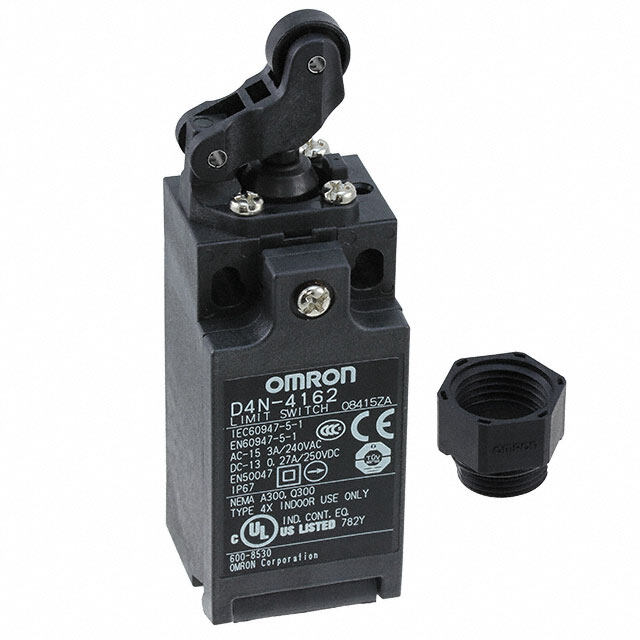
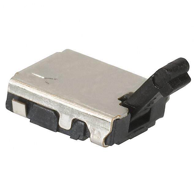
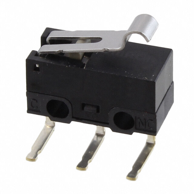
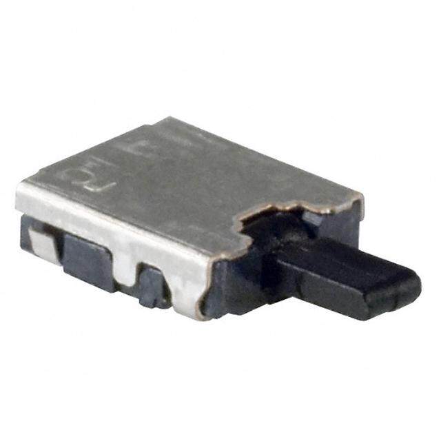
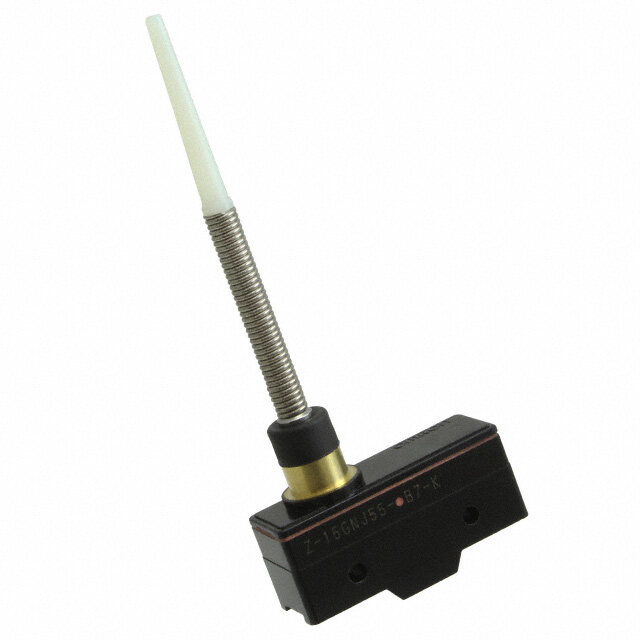
| 产品图片 |
|
| rohs | 否无铅 / 符合限制有害物质指令(RoHS)规范要求 |
| 产品系列 | 基本/快动开关,C&K Components 2HBFX985HB |
| mouser_ship_limit | 该产品可能需要其他文件才能进口到中国。 |
| 数据手册 | http://www.ck-components.com/index.php?module=media&action=Display&cmpref=15158&lang=en&width=&height=&format=&alt= |
| 产品型号 | 2HBFX985 |
| 产品培训模块 | http://www.digikey.cn/PTM/IndividualPTM.page?site=cn&lang=zhs&ptm=30211http://www.digikey.cn/PTM/IndividualPTM.page?site=cn&lang=zhs&ptm=30212http://www.digikey.cn/PTM/IndividualPTM.page?site=cn&lang=zhs&ptm=30218http://www.digikey.cn/PTM/IndividualPTM.page?site=cn&lang=zhs&ptm=30222http://www.digikey.cn/PTM/IndividualPTM.page?site=cn&lang=zhs&ptm=30457 |
| 产品种类 | 基本/快动开关 |
| 侵入防护 | IP65 - 防尘,耐水 |
| 其它名称 | *2HBFX985 |
| 包装 | 散装 |
| 商标 | C&K Components |
| 安装 | Panel |
| 安装类型 | 底座安装 |
| 工作位置 | 1.120" (28.45mm) |
| 工作力 | 3 N |
| 工作温度 | -55°C ~ 150°C |
| 差动行程 | 0.008"(0.2mm) |
| 开关功能 | 开-瞬时 |
| 执行器 | Lever |
| 操作力,扭矩 | 283gf |
| 机械寿命 | - |
| 标准包装 | 1 |
| 特性 | - |
| 电压额定值AC | 125 V |
| 电气寿命 | 150,000 次循环 |
| 电流额定值 | 20 A |
| 电路 | SPDT |
| 端子类型 | 螺丝端子 |
| 端接类型 | Screw |
| 系列 | HB |
| 致动器类型 | 按片,滚轴 |
| 触点形式 | SPDT |
| 超行程 | 0.090" (2.3mm) |
| 释放力 | 85gf |
| 预行程 | 0.080" (2.0mm) |
| 额定电压-AC | 125V |
| 额定电压-DC | 125V |
| 额定电流 | 20A(AC), 500mA(DC) |





- 商务部:美国ITC正式对集成电路等产品启动337调查
- 曝三星4nm工艺存在良率问题 高通将骁龙8 Gen1或转产台积电
- 太阳诱电将投资9.5亿元在常州建新厂生产MLCC 预计2023年完工
- 英特尔发布欧洲新工厂建设计划 深化IDM 2.0 战略
- 台积电先进制程称霸业界 有大客户加持明年业绩稳了
- 达到5530亿美元!SIA预计今年全球半导体销售额将创下新高
- 英特尔拟将自动驾驶子公司Mobileye上市 估值或超500亿美元
- 三星加码芯片和SET,合并消费电子和移动部门,撤换高东真等 CEO
- 三星电子宣布重大人事变动 还合并消费电子和移动部门
- 海关总署:前11个月进口集成电路产品价值2.52万亿元 增长14.8%

PDF Datasheet 数据手册内容提取
HB Series Single Pole Standard Precision Snap-acting Switches Features/Benefits Typical Applications • L ow differential travel, high repeatability • Thermostats • Long life—150,000 cycles typical • Motors • Single and double pole circuitry • Industrial controls • Sealed actuator and case Specifications Materials CONTACT RATING: From low level* to 20 AMPS @ 480 V AC; SWITCH HOUSING: Heat resistant/electrical grade phenolic. see ELECTRICAL RATING option section for complete listings. INSERTS: Brass alloy. ELECTRICAL LIFE: 150,000 cycles at 20 AMPS @ 250 V AC. ACTUATOR BUTTON: Moisture resistant phenolic. consult Customer Service Center for typical life at other ratings. SPRING: Copper alloy. INSULATION RESISTANCE: 1,000 M ohm min. PIVOT: Brass alloy. DIELECTRIC STRENGTH: 1,500 Vrms min. @ sea level. MOVABLE CONTACTS: Gold alloy for ratings 1 AMP or less. OPERATING TEMPERATURE: –67ºF to 302ºF (–55ºC to 150ºC). Fine silver for ratings greater than 1 AMP and motor load OPERATING FORCE: From 4 oz. to 26 oz. max. at actuator ratings less than 1/2 HP @ 125 V AC. Silver alloy for motor button available. load ratings 1/2 HP @ 125 V AC or greater. MOUNTING SCREWS: Torque 3 in/lbs max. STATIONARY CONTACTS: Gold alloy for ratings 1 AMP or less. J (Note: Exceeding 3 in/lbs torque may change operating Fine silver welded to copper base for ratings greater than characteristics and increase the possibility of cracking 1 AMP and motor load ratings less than 1/2 HP @ 125 V AC. switch case). Silver alloy on copper base for motor load ratings 1/2 HP @ S TERMINAL SCREWS: Torque 4 in/lbs max. 125 V AC or greater. n a PANEL MOUNTING BUSHING: Torque 4-6 in/lbs max. TERMINALS: Brass alloy, bright tin plated. p DEGREE OF PROTECTION: IP65; Dust-proof, water splash and -a dew condensation. NOTE: Specifications and materials listed above are for switches with standard options. c For information on specific and custom switches, consult Customer Service Center. t * Low Level=conditions where no arcing occurs during switching, i.e., 0.4 VA max. @ in 20 V AC or DC max. g Build-A-Switch To order, simply select desired option from each category and place in the appropriate box. Available options are shown and described on pages J-72 through J-76. For additional options not shown in catalog, consult Customer Service Center. H B S S C Series HB Precision Snap-acting Switches Operating Force KG 18 oz./510 grams Mounting Style Circuitry Function GF 4 oz./113 grams S Standard C SPDT S SP Contact Separation KA 9 oz./255 grams 2 .020” KC 13 oz./368 grams 1 .010” KH 20 oz./567 grams 4 .040” PB 26 oz./737 grams 7 .070” Electrical Rating B4 20 A, 125, 250, 480 V AC; 0.25 A, 250 V DC; 0.5 A, 125 V DC Actuator A2 5 A, 125, 250 V AC P0 Pin plunger B6 20 A, 125, 250, 480 V AC; 0.25 A, A0 Lever roller Terminations 250 V DC; 0.5 A, 125 V DC; 3/4 HP, D0 Stub plunger 11 Flat base, solder, 4-40 screws 125 V AC; 1 1/2 HP, 25O V AC F0 Reverse acting lever roller 41 Flat base, .250” quick connect F5 1 A,125 V AC; 1 A, 3O V DC J0 High overtravel plunger 55 Step base, cup washers, 6-32 screws F9 22 A, 125, 277 V AC; 15 A, 480 V AC; R5 Perpendicular roller plunger 1/4 HP, 125 V AC; 1/2 HP, 250 V AC T0 Lever TS Sealed Lever Y0 Reverse acting lever Dimensions are shown: mm Specifications and dimensions subject to change www.ckswitches.com J–71
HB Series Single Pole Standard Precision Snap-acting Switches Sealed Actuator and Case To provide reliable service under environmental conditions that might damage standard precision switches, various HB Series switch models are sealed against the entrance of airborne contaminants and/or splashing liquids. The clearance between the operating plunger and the cover is sealed with a silicone boot and the base cover joint is sealed with an epoxy adhesive. These models are designed to meet requirements of IP65 (dust proof, water splash and dew condensation). For additional information on sealed switches, consult our Customer Service Center. SERIES HB PRECISION SNAP-ACTING SWITCHES FUNCTION S SINGLE POLE SWITCH J OPER. POS. .625 ± .015 (15,88 ± 0,38) g n i t c a - p Single Pole a n S NOTE: To select switching function, see CIRCUITRY section, page J-52. CONTACT SEPARATION OCPOTDIOEN SNEOPMARINAATLIO CNO (NinT./AmCmT) .0004 DIFFFEORRE VNATRIAIOL UTSR ACVOENLT ASCPET CSIEFIPCAARTAIOTNIO LNISMITS .0002 INCH 2 .020 (0,51) Switches with 1 AMP rating (option CONTACT code ‘F5’) are available only with SEPARATION 0 .001 .002 .003 .004 .005 1 .010 .020 contact separation (option ‘2’). (0,25) 1 Switches with 1/2 HP, 125 V AC rating 4 .040 or greater (option codes ‘B5 and B6’) 2 (1,02) are not available with .010 contact 7 .070 separation (option code ‘1’). 4 (1,78) 7 .0015 Dimensions are shown: Inch (mm) Specifications and dimensions subject to change J–72 www.ckswitches.com
HB Series Single Pole Standard Precision Snap-acting Switches OPERATING FORCE OPERATING FORCE SPECIFICATION LIMITS OPTION MAXIMUM OPERATING STANDARDCONTACT FOR VARIOUS CONTACT SEPARATIONS CODE FORCE (OZ./GRAMS) SEPARATION (inch) OUNCES KG 51180 .020 SECPOANRTAATCIOTN 4 7 9 13 14 1820 26 30 GF 4 .010 .010 115 KA 9 .010 .020 255 .040 KC 13 .020 370 .070 KH 52700 .040 STANDARD RANGE MAXIMUM LIMITS AVAILABLE PB 26 .070 740 NOTE: All listed differential travel characteristics are based on standard operating force andcontact separation. For any other force or contact separation, consult Customer Service Center. Operating force varies with actuator option, see ACTUATOR option section. ELECTRICAL RATING OPTION CODE MOVABLECONTACT STATIONARY CONTACT ELECTRICALRATING J B4 20 AMPS @ 125, 250 & 480 V AC; 0.25 AMPS @ 250 V DC; 0.5 AMPS @ Fine silver welded to 125 V DC (UL). A2 Fine silver. copper base. 5 AMPS @ 125 & 250 V AC (UL). S n B6 Precious metal alloy. Precious metal alloy. 20 AMPS @ 125, 250 & 480 V AC; 0.25 AMP @ 250 V DC; 0.5 AMP @ a 125 V DC; 3/4 HP @ 125 V AC; 1 1/2 HP @ 250 V AC (UL). p F5 Gold alloy. Gold alloy. Low level* to 1 AMP @ 125 V AC; 1 AMP @ 30 V DC (UL). - a Fine silver welded to 22 AMPS @ 125 & 277 V AC; 15 AMPS @ 480 V AC; 1/4 HP @ 125 V AC; c F9 Fine silver. copper base. 1/2 HP @ 250 V AC; 277 V AC (UL). t i n g * Note: See Technical Data section of this catalog for RoHS compliant and compatible definition and specifications. AVAILABLECOMBINATIONS OPERATING FORCE (oz.) ELECTRICAL 4 9 13 18 20 26 RATING GF KA KC KG KH PB A2 • • • • • • B4 x • • • • • B6 x x x • • • F5 x x • • • • F9 x x x • • • •AVAILABLE xNOTAVAILABLE All models with all options Consult Customer Service center for availability and delivery of nonstandard ratings. * Low Level=conditions where no arcing occurs during switching, i.e., 0.4 VA max. @ 20 V AC or DC max. Dimensions are shown: Inch (mm) Specifications and dimensions subject to change www.ckswitches.com J–73
HB Series Single Pole Standard Precision Snap-acting Switches MOUNTING STYLE S Standard NOTE: Mounting holes will accept pins or screws of .139 dia. (3,53) max. on 1.000 ± .002 (25,4 ± 0,05) centers. NOTE: Torque mounting screws 3 inlbs max. ACTUATOR A NO. OPTION CODE POLES FIG. DIM. A DIM. B DIM. C DIM. D D A C D C A0 SP 1 .86 1.120 ± .060 .38 dia. 1.03 (21,8) (28,45 ± 1,52) (9,7Ø) (26,2) D0 SP 3 (2.932,4 ) (2.814,444 ±± .002,501 ) — — B B F0 SP 2 .09 1.120 ± .050 .38 dia. .74 (2,3) (28,45 ± 1,27) (9,7Ø) (18,8) J J0 SP 4 .86 .860±.030 — — (21,8) (21,84±0,76) FIG. 1 FIG. 2 g P0 SP 5 .92 .625 ± .010 — — Lever Roller Lever Roller (23,4) (15,88 ± 0,25) n ti R5 SP 6 .92 .62 .50 dia. 0.61 A c (23,4) (15,7) (12,7Ø) (15,5) a p- T0 SP 7 (13.33,1207 ) (1.782,208 ±± .016,502 ) 1(2.063,2 dØia)). — a TS* SP 7 1.47 .720 ± .060 1.03 dia. — B n (37,3) (18,28 ± 1,52) (26,2Ø) S Y0 SP 8 .05 .720 ± .030 .74 dia. 2.65 (1,3) (18,29 ± 0,76) (18,8Ø) (6,73) FIG. 3 Stub Plunger * Actuators sealed against the entrance of airborne contaminants and/or splashing liquids. C 0.33 A (8,40) Dia. A B B A D PANEL MOUNTING FIG. 5 Pin Plunger .640 ± .020 B FIG. 4 FIG. 6 Plunger .50 DIA. Perpendicular Roller Plunger (12,70?) D C A C A B B FIG. 8 FIG. 7 Reverse Acting Lever Lever Dimensions are shown: Inches (mm) Specifications and dimensions subject to change www.ckswitches.com J–74
HB Series Single Pole Standard Precision Snap-acting Switches ACTUATOR ACTUATOR * SEALEDACTUATOR OPTION CODE A0 D0 F0 J0 P0 R5 T0 Y0 TS 4 GF — — — — 115 — — — — 3 9.5 10 10 9 10 2 10 2 KA 85 269 284 284 255 284 60 284 56 MAXIMUM 13 10 13 13 13 10 KC — — — OPERATING 370 284 370 370 370 284 FORCE 3.5 18 2.5 2.5 KG — — — — — (OZ./GRAMS) 100 510 71 71 4 20 20 20 20 20 3 20 3 KH 115 570 570 570 570 570 85 570 85 4.5 26 20 26 26 26 3.5 20 3.5 PB 130 740 570 740 740 740 100 570 100 1 GF — — — — 28 — — — — .75 4 3 4 4 4 .5 3 .5 KA 21 110 85 110 110 110 14 85 14 MINIMUM 1.7 4 3 4 4 4 3 KC — — RELEASE 48 110 85 110 110 110 85 FORCE .75 4 .5 .5 KG — — — — — (OZ./GRAMS) 21 110 14 14 .75 4 3 4 4 4 .5 3 .5 KH 21 110 85 110 110 110 14 85 14 J .75 4 3 4 4 4 .5 3 .5 PB 21 110 85 110 110 110 14 85 14 S NOTE:For basic switch operating forces, see page J-71. * Actuators sealed against the entrance of airborne contaminants and/or splashing liquids. n a p - a ACTUATOR * SEALEDACTUATOR c OPTION t CODE A0 D0 F0 J0 P0 R5 T0 Y0 TS in g .0005 GF — — — — (0,013) — — — — .020 .0005 .005 .0005 .047 .005 .047 KA — — (0,51) (0,013) (0,13) (0,013) (1,19) (0,13) (1,19) MAXIMUM .002 .008 .002 .009 KC — — — — — DIFFERENTIAL (0,05) (0,20) (0,05) (0,23) TRAVEL .062 .003 .078 .078 KG — — — — — (IN/MM) (1,57) (0,08) (1,98) (1,98) .080 .003 .020 .003 .093 .020 .093 KH — — (2,03) (0,76) (0,51) (0,08) (2,36) (0,51) (2,36) .125 .007 .030 .005 .156 .031 .156 PB — — (3,18) (0,18) (0,76) (0,13) (3,96) (0,79) (3,96) .020 GF — — — — (0,51) — — — — .312 .020 0.8 .015 .015 .015 .38 .09 .38 KA (7,92) (0,51) (2,0) (0,38) (0,38) (0,38) (9,7) (2,3) (9,7) .020 0.8 .020 .020 .020 .09 MAXIMUM KC — — — (0,51) (2,0) (0,51) (0,51) (0,51) (2,3) PRETRAVEL .312 .025 .38 .38 (IN/MM) KG — — — — — (7,92) (0,64) (9,7) (9,7) .38 .025 0.9 .025 .025 .025 .38 0.9 .38 KH (9,7) (0,64) (2,3) (0,64) (0,64) (0,64) (9,7) (2,3) (9,7) .38 .030 0.9 .030 .030 .030 .38 0.9 .38 PB (9,7) (0,76) (2,3) (0,76) (0,76) (0,76) (9,7) (2,3) (9,7) .005 GF — — — — (0,13) — — — — .156 .055 .06 .22 .005 .141 .19 .06 .19 KA (3,96) (1,40) (1,5) (5,6) (0,13) (3,58) (4,8) (1,5) (4,8) .055 0.9 .22 .005 .141 0.9 MINIMUM KC — — — (1,40) (2,3) (5,6) (0,13) (3,58) (2,3) OVERTRAVEL .156 .005 .19 .19 (IN/MM) KG — — — — — (3,96) (0,13) (4,8) (4,8) .156 .055 0.9 .22 .005 .141 .19 0.9 .19 KH (3,96) (1,40) (2,3) (5,6) (0,13) (3,58) (4,8) (2,3) (4,8) .156 .055 0.9 .22 .005 .141 .19 0.9 .19 PB (3,96) (1,40) (2,3) (5,6) (0,13) (3,58) (4,8) (2,3) (4,8) Dimensions are shown: Inch (mm) Specifications and dimensions subject to change www.ckswitches.com J–75
HB Series Single Pole Standard Precision Snap-acting Switches TERMINATIONS 11 41 FLAT BASE, SOLDER TERMINALS AND 4-40 SCREWS FLAT BASE, .250” QUICK CONNECT TERMINALS NOTE: Switches with flat base option have molded ribs that provide increased creep distance. 55 J STEP BASE, 6-32 SCREWS AND CUP WASHERS g n i t c a - p a n S NOTE: Switches with step base option provide wide electrical clearance for screw terminal options. CIRCUITRY C DT (Double Throw, Normally Closed & Normally Open) Dimensions are shown: Inches (mm) Specifications and dimensions subject to change www.ckswitches.com J–76
Mouser Electronics Authorized Distributor Click to View Pricing, Inventory, Delivery & Lifecycle Information: C &K Switches: 2HBFX985 2HB374-1 HBS4KCB4SA011C HBS2KHB6SP055C HBS2KAB4ST011C HBS2KHB4SA011C HBS2KGB6SP055C HBS7KHB6STS41C HBS2KGX3SA011C HBS7PBB4SP011C HBS2KHX3SJ055C HBS1KAB4SP011C HBS2KGB4STS41C HBS2KHF5SA041C HBS2KHB6SD055C HBS4KHB4SP011C HBS2KAB4SP011C HBS2KGB4SP055C HBS2KHB6SP011C HBS2KGB4SF011C HBS1GFA2SP011C HBS7KHB4SJ055C HBS2KAF5SF055C HBS1KAA2SP011C HBS2KHB4SF055C HBS1KAX3SP011C HBS7KHB4SP055C HBS7PBB4SJ055C HBS2KHF9SP041C HBS2KGB6STS41C HBS2KHB6ST055C HBS2KGX3SA055C HBS4KGB4ST011C HBS1KGF9SP011C HBS4KHB6STS55C HBS2KHB4SA041C HBS1KAB4SP055C HBS2KGX3SA041C HBS2KAF5SR541C HBS2KGX3ST011C HBS2KAB4ST055C HBS7PBB4SJ011C HBS2KHB6SJ055C HBS2KGB4STS55C HBS2KCF5SR555C HBS2KGB6SF055C HBS1KAX3SJ055C HBS2KHB6SA055C HBS2KGX3ST055C HBS4PBB4SP011C HBS2KGF5SA011C HBS7PBA2SP041C HBS2PBB4ST011C HBS2KAF9SF055C HBS1KAA2SJ041C HBS2KHF9SJ055C HBS1KGX3ST041C HBS1KAA2SA011C HBS2KGX3SP055C HBS1KGF9SP011CU HBS2KGF9SJ055C HBS2KGX3STS11C HBS4KHB6SF055C HBS2KAA2SJ041C HBS2KGB6ST055C HBS2KGF5SJ011C HBS2PBF5SJ055C HBS1KGB4SP011C HBS7PBA2SD041C HBS2KHB6SF055C

 Datasheet下载


