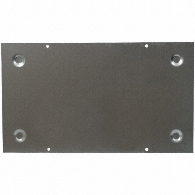
- 型号: 2896173
- 制造商: Phoenix Contact
- 库位|库存: xxxx|xxxx
- 要求:
| 数量阶梯 | 香港交货 | 国内含税 |
| +xxxx | $xxxx | ¥xxxx |
查看当月历史价格
查看今年历史价格
2896173产品简介:
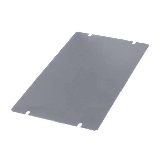
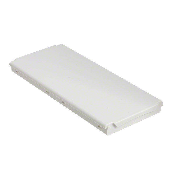
ICGOO电子元器件商城为您提供2896173由Phoenix Contact设计生产,在icgoo商城现货销售,并且可以通过原厂、代理商等渠道进行代购。 2896173价格参考。Phoenix Contact2896173封装/规格:盒组件, Plastic, Polycarbonate Cover, Lid 4.236" W (107.60mm) Gray。您可以下载2896173参考资料、Datasheet数据手册功能说明书,资料中有2896173 详细功能的应用电路图电压和使用方法及教程。
| 参数 | 数值 |
| 产品目录 | |
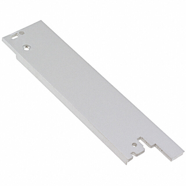
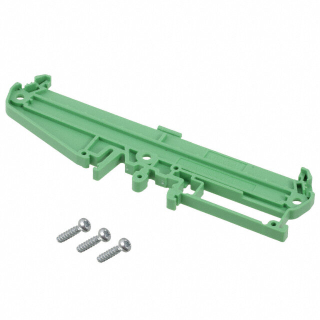
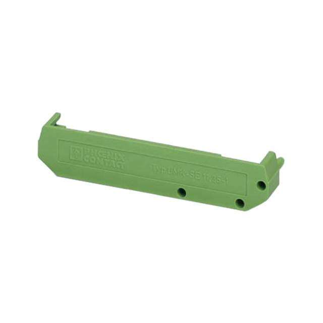
| 描述 | COVER FOR BC 107.6 HOUSING接线端子工具和配件 BC 107.6 DKL R KMGY |
| 产品分类 | |
| 品牌 | Phoenix Contact |
| 产品手册 | http://www.phoenixcontact.com/us/products/2896173/pdf |
| 产品图片 |
|
| rohs | 符合RoHS无铅 / 符合限制有害物质指令(RoHS)规范要求 |
| 产品系列 | 接线端子工具和配件,Phoenix Contact 2896173BC |
| 数据手册 | |
| 产品型号 | 2896173 |
| PCN设计/规格 | |
| 产品 | Tools & Accessories |
| 产品种类 | 接线端子工具和配件 |
| 其它名称 | 277-2909 |
| 单位重量 | 630 g |
| 商标 | Phoenix Contact |
| 大小/尺寸 | 4.236" 宽 (107.60mm) |
| 工厂包装数量 | 10 |
| 材料 | 塑料 - 聚碳酸酯 |
| 标准包装 | 10 |
| 特性 | - |
| 类型 | 外壳,盖 |
| 配套使用产品/相关产品 | BC 107.6 体座系统 |
| 配用 | /product-detail/zh/2896270/277-2869-ND/2514935 |
| 零件号别名 | BC_107,6_DKL_R_KMGY BC1076DKLRKMGY |
| 颜色 | 灰 |


- 商务部:美国ITC正式对集成电路等产品启动337调查
- 曝三星4nm工艺存在良率问题 高通将骁龙8 Gen1或转产台积电
- 太阳诱电将投资9.5亿元在常州建新厂生产MLCC 预计2023年完工
- 英特尔发布欧洲新工厂建设计划 深化IDM 2.0 战略
- 台积电先进制程称霸业界 有大客户加持明年业绩稳了
- 达到5530亿美元!SIA预计今年全球半导体销售额将创下新高
- 英特尔拟将自动驾驶子公司Mobileye上市 估值或超500亿美元
- 三星加码芯片和SET,合并消费电子和移动部门,撤换高东真等 CEO
- 三星电子宣布重大人事变动 还合并消费电子和移动部门
- 海关总署:前11个月进口集成电路产品价值2.52万亿元 增长14.8%
PDF Datasheet 数据手册内容提取
BC... Installation component housing of the BC... series Data sheet 102981_en_05 © PHOENIX CONTACT 2016-02-12 1 Description The installation component housings of the BC... series are The PCBs can be installed parallel or perpendicular to the suitable for use in common installation distributor boxes and DIN rail starting at 2TE. The perpendicular PCBs can, how- comply with the standard DIN 43880. ever, be aligned either parallel or transverse to the DIN rail. In all cases the PCBs can be snapped in at different loca- The component housings are available in five different de- tions. sign widths, from the width of one horizontal pitch (1TE = 17.8 mm) up to nine horizontal pitches (9TE = 161.6 mm). The cover is available in two versions: Starting with the design width 2TE (35.6 mm), the installa- – Transparent, hinged and can be sealed tion space for PCB connection technology is available in two – In the same light gray color as the housing, permanently different installation depths: snapped onto the upper housing part – The connection technology for BC...U11 has 11 mm of The component housings are mounted on an NS 35 DIN rail. space. This is ideal for the use of connection technolo- Optionally, a 16-pos. DIN rail connector can be inserted in gy with small pitch dimensions (e.g. COMBICON com- the DIN rail. This serves to establish automatic contact from pact) device to device. With the bus connector, data and energy – The installation space for connection technology with transmission can be serial or parallel (4 x power, 2 x serial, BC...U22 has been maximized to 22 mm of space. For 10 x parallel). Individual devices can be easily plugged in or instance, double-level connection terminal blocks or unplugged without breaking up the group of modules. RJ45 connectors can be mounted. With BC 161,6 modular, the side panels in each of the six segments on each side of the housing can be arranged in three different positions. When the side panel is located at the innermost position, the installation space for connection technology is maximized to 22 mm. The installation space for connection technology is 11 mm for the middle side panel position. When the side panel is located at the outer- most position, the installation space for connection technol- ogy is closed off. The 3D housing data can be found at phoenixcontact.net/products. Make sure you always use the latest documentation. It can be downloaded at phoenixcontact.net/products. This data sheet is valid for all products listed on the following page:
BC... installation component housing Overview of BC Products Table of contents 2 Overview of BC Products 1 Description..................................................................1 Housing cover, 2 Overview of BC Products............................................2 transparent with fitted cover 3 Ordering data..............................................................4 3.1 Ordering data (1TE to 9TE).................................4 Housing cover, light gray 3.2 Order key for BC 161,6 modular – upper part......7 3.3 Selecting the right connection technology...........8 Upper housing part 4 Technical data.............................................................9 Filler plug U22Upper housing part U11 Filler plug U22 U11 5 Housing dimensions..................................................10 5.1 Dimensions of housing......................................10 5.2 Dimensions of DIN rail connector......................11 6 PCB arrangement for BC 17,8 (1TE).........................12 Lower housing part 6.1 PCB dimensions................................................12 6.2 Inner dimensions...............................................14 6.3 Circuit diagram of DIN rail connector with 2 and 3 slots......................................................15 6.4 Dimensional drawing of connector for DIN rail DIN rail connector HBUS... connector..........................................................15 Powerplug 7 PCB arrangement for BC 2TE – 9TE.........................16 7.1 Plug-in positions for horizontal PCBs.................16 7.2 Circuit board dimensions for PCB 1, horizontal.17 7.3 Circuit board dimensions for PCB 2 to 8, horizontal Figure 1 Overview 25 7.4 Circuit board dimensions for PCB 9, horizontal.26 7.5 Perpendicular PCBs – transverse to the DIN rail30 7.6 Perpendicular PCBs – parallel to the DIN rail.....31 8 PCB arrangement for BC 161,6 modular...................32 8.1 Plug-in positions for horizontal PCBs.................32 8.2 Versions for the terminal installation space........33 8.3 Circuit board dimensions for PCB 1, horizontal.34 8.4 Circuit board dimensions for PCB 2 to 8, horizontal 36 8.5 Circuit board dimensions for PCB 9, horizontal.40 8.6 Perpendicular PCBs (BC 161,6 modular)..........41 9 DIN rail connector with 1 slot (2TE – 9TE).................45 9.1 Circuit diagram of DIN rail connector.................45 9.2 Dimensional drawing of connector for DIN rail connector..........................................................45 102981_en_05 PHOENIX CONTACT 2
BC... installation component housing Overview of BC Products BC 17,8… BC 71,6… (1TE) BC 53,6… (4TE) BC 35,6… (3TE) (2TE) HBUS 53,6…3S… HBUS 35,6…2S… HBUS 71,6…1S… HBUS 53,6…1S… BC 161,6… HBUS 35,6…1S… (9TE) BC 107,6… (6TE) HBUS 161,6…1S… HBUS 107,6…1S… Figure 2 Overview of design widths with corresponding DIN rail connector HBUS 102981_en_05 PHOENIX CONTACT 3
BC... installation component housing Ordering data 3 Ordering data 3.1 Ordering data (1TE to 9TE) Design width 17.8 mm (1TE) Description Type Order No. Pcs. / Pkt. Lower housing part BC 17,8 UT HBUS BK 2896241 10 Upper housing part, for horizontal PCB connection with 3.5 mm or 5 mm BC 17,8 OTU MKDSO KMGY 2279732 10 pitch Housing cover, permanently snapped onto the upper housing part, in the BC 17,8 DKL R KMGY 2896144 10 same light gray color as the housing Housing cover, hinged, can be sealed, transparent, including fitted cover BC 17,8 DKL S TRANS 2896102 10 Accessories PCB terminal block, for soldering onto PCB, Left MKDSO 1,5/ 4-L-3,5 KMGY 2278432 50 3.5 mm pitch, number of positions: 4 Right MKDSO 1,5/ 4-R-3,5 KMGY 2278429 50 PCB terminal block, for soldering onto PCB, 5 mm pitch, Left MKDSO 2,5/3-L KMGY 2854102 50 number of positions: 3 Right MKDSO 2,5/3-R KMGY 2854092 50 DIN rail connector, 16-pos., 18-pos. slots to the PCB 2 Slots HBUS 35,6-16P-2S BK 2896319 10 3 Slots HBUS 53,6-16P-3S BK 2896322 10 Power plug for DIN rail connector, with 16 free cable ends Socket strip BL2-2,54/16-ST 2896335 50 with a cross section of 0.25 mm², 500 mm long Pin strip SL2-2,54/16-ST 2896348 50 Cover cap set, 3-piece, for protecting empty DIN rail connectors HBUS-B SET BK 2278173 10 Filler plug for empty terminal space ME 17,5 OTU-MKDSO KMGY 2854115 50 Design width 35.6 mm (2TE) Description Type Order No. Pcs. / Pkt. Lower housing part BC 35,6 UT HBUS BK 2896254 10 Upper housing part, with vents, terminal installation depth 11.1 mm BC 35,6 OT U11 KMGY 2896034 10 Upper housing part, with vents, terminal installation depth 22.35 mm BC 35,6 OT U22 KMGY 2896047 10 Housing cover, permanently snapped onto the upper housing part, in the BC 35,6 DKL R KMGY 2896157 10 same light gray color as the housing Housing cover, hinged, can be sealed, transparent, including fitted cover BC 35,6 DKL S TRANS 2896115 10 Accessories DIN rail connector, 16-pos., 18-pos. slot to the PCB 1 Slot HBUS 35,6-16P-1S BK 2896283 10 Power plug for DIN rail connector, with 16 free cable ends Socket strip BL2-2,54/16-ST 2896335 50 with a cross section of 0.25 mm², 500 mm long Pin strip SL2-2,54/16-ST 2896348 50 Cover cap set, 3-piece, for protecting empty DIN rail connectors HBUS-B SET BK 2278173 10 Filler plug for empty terminal space, 17.6 mm design 11 mm BC 17,6 BS U11 KMGY 2896186 50 width, for terminal installation depth 22 mm BC 17,6 BS U22 KMGY 2896199 50 Filler plug for empty terminal space, 35.6 mm design 11 mm BC 35,6 BS U11 KMGY 2896209 50 width, for terminal installation depth 22 mm BC 35,6 BS U22 KMGY 2896212 50 102981_en_05 PHOENIX CONTACT 4
BC... installation component housing Ordering data Design width 53.6 mm (3TE) Description Type Order No. Pcs. / Pkt. Lower housing part BC 53,6 UT HBUS BK 2896403 10 Upper housing part, with vents, terminal installation depth 11.1 mm BC 53,6 OT U11 KMGY 2896416 10 Upper housing part, with vents, terminal installation depth 22.35 mm BC 53,6 OT U22 KMGY 2896429 10 Housing cover, permanently snapped onto the upper housing part, in the BC 53,6 DKL R KMGY 2896432 10 same light gray color as the housing Housing cover, hinged, can be sealed, transparent, including fitted cover BC 53,6 DKL S TRANS 2896445 10 Accessories DIN rail connector, 16-pos., 18-pos. slot to the PCB 1 Slot HBUS 53,6-16P-1S BK 2896458 10 Power plug for DIN rail connector, with 16 free cable ends Socket strip BL2-2,54/16-ST 2896335 50 with a cross section of 0.25 mm², 500 mm long Pin strip SL2-2,54/16-ST 2896348 50 Cover cap set, 3-piece, for protecting empty DIN rail connectors HBUS-B SET BK 2278173 10 Filler plug for empty terminal space, 17.6 mm design 11 mm BC 17,6 BS U11 KMGY 2896186 50 width, for terminal installation depth 22 mm BC 17,6 BS U22 KMGY 2896199 50 Filler plug for empty terminal space, 35.6 mm design 11 mm BC 35,6 BS U11 KMGY 2896209 50 width, for terminal installation depth 22 mm BC 35,6 BS U22 KMGY 2896212 50 Filler plug for empty terminal space, 53.6 mm design 11 mm BC 53,6 BS U11 KMGY 2896225 50 width, for terminal installation depth 22 mm BC 53,6 BS U22 KMGY 2896238 50 Design width 71.6 mm (4TE) Description Type Order No. Pcs. / Pkt. Lower housing part BC 71,6 UT HBUS BK 2896267 10 Upper housing part, with vents, terminal installation depth 11.1 mm BC 71,6 OT U11 KMGY 2896050 10 Upper housing part, with vents, terminal installation depth 22.35 mm BC 71,6 OT U22 KMGY 2896063 10 Housing cover, permanently snapped onto the upper housing part, in the BC 71,6 DKL R KMGY 2896160 10 same light gray color as the housing Housing cover, hinged, can be sealed, transparent, including fitted cover BC 71,6 DKL S TRANS 2896128 10 Accessories DIN rail connector, 16-pos., 18-pos. slot to the PCB 1 Slot HBUS 71,6-16P-1S BK 2896296 10 Power plug for DIN rail connector, with 16 free cable ends Socket strip BL2-2,54/16-ST 2896335 50 with a cross section of 0.25 mm², 500 mm long Pin strip SL2-2,54/16-ST 2896348 50 Cover cap set, 3-piece, for protecting empty DIN rail connectors HBUS-B SET BK 2278173 10 Filler plug for empty terminal space, 17.6 mm design 11 mm BC 17,6 BS U11 KMGY 2896186 50 width, for terminal installation depth 22 mm BC 17,6 BS U22 KMGY 2896199 50 Filler plug for empty terminal space, 35.6 mm design 11 mm BC 35,6 BS U11 KMGY 2896209 50 width, for terminal installation depth 22 mm BC 35,6 BS U22 KMGY 2896212 50 102981_en_05 PHOENIX CONTACT 5
BC... installation component housing Ordering data Design width 107.6 mm (6TE) Description Type Order No. Pcs. / Pkt. Lower housing part BC 107,6 UT HBUS BK 2896270 10 Upper housing part, with vents, terminal installation depth 11.1 mm BC 107,6 OT U11 KMGY 2896076 10 Upper housing part, with vents, terminal installation depth 22.35 mm BC 107,6 OT U22 KMGY 2896089 10 Housing cover, permanently snapped onto the upper housing part, in the BC 107,6 DKL R KMGY 2896173 10 same light gray color as the housing Housing cover, hinged, can be sealed, transparent, including fitted cover BC 107,6 DKL S TRANS 2896131 10 Accessories DIN rail connector, 16-pos., 18-pos. slot to the PCB 1 Slot HBUS 107,6-16P-1S BK 2896306 10 Power plug for DIN rail connector, with 16 free cable ends Socket strip BL2-2,54/16-ST 2896335 50 with a cross section of 0.25 mm², 500 mm long Pin strip SL2-2,54/16-ST 2896348 50 Cover cap set, 3-piece, for protecting empty DIN rail connectors HBUS-B SET BK 2278173 10 Filler plug for empty terminal space, 17.6 mm design 11 mm BC 17,6 BS U11 KMGY 2896186 50 width, for terminal installation depth 22 mm BC 17,6 BS U22 KMGY 2896199 50 Filler plug for empty terminal space, 35.6 mm design 11 mm BC 35,6 BS U11 KMGY 2896209 50 width, for terminal installation depth 22 mm BC 35,6 BS U22 KMGY 2896212 50 Filler plug for empty terminal space, 53.6 mm design 11 mm BC 53,6 BS U11 KMGY 2896225 50 width, for terminal installation depth 22 mm BC 53,6 BS U22 KMGY 2896238 50 Design width 161.6 mm (9TE) Description Type Order No. Pcs. / Pkt. Lower housing part BC 161,6 UT HBUS BK 2278500 10 Upper housing part, with vents, terminal installation depth 11.1 mm BC 161,6 OT U11 KMGY 2278513 10 Upper housing part, with vents, terminal installation depth 22.35 mm BC 161,6 OT U22 KMGY 2278526 10 Housing cover, permanently snapped onto the upper housing part, in the BC 161,6 DKL R KMGY 2278539 10 same light gray color as the housing Housing cover, hinged, can be sealed, transparent, including fitted cover BC 161,6 DKL S TRANS 2278542 10 Accessories DIN rail connector, 16-pos., 18-pos. slot to the PCB 1 Slot HBUS 161,6-16P-1S BK 2278555 10 Power plug for DIN rail connector, with 16 free cable ends Socket strip BL2-2,54/16-ST 2896335 50 with a cross section of 0.25 mm², 500 mm long Pin strip SL2-2,54/16-ST 2896348 50 Cover cap set, 3-piece, for protecting empty DIN rail connectors HBUS-B SET BK 2278173 10 Filler plug for empty terminal space, 17.6 mm design 11 mm BC 17,6 BS U11 KMGY 2896186 50 width, for terminal installation depth 22 mm BC 17,6 BS U22 KMGY 2896199 50 Filler plug for empty terminal space, 35.6 mm design 11 mm BC 35,6 BS U11 KMGY 2896209 50 width, for terminal installation depth 22 mm BC 35,6 BS U22 KMGY 2896212 50 Filler plug for empty terminal space, 53.6 mm design 11 mm BC 53,6 BS U11 KMGY 2896225 50 width, for terminal installation depth 22 mm BC 53,6 BS U22 KMGY 2896238 50 102981_en_05 PHOENIX CONTACT 6
BC... installation component housing Ordering data 3.2 Order key for BC 161,6 modular – upper part With BC 161,6 modular, the side panel for each segment on Ordering data for example configurations each side of the housing can be arranged in three different Ordering data for upper part of BC 161,6 modular positions. Description Type Order No. Pcs. / – When the side panel is located at the innermost posi- Pkt. tion, the installation space for connection technology is Upper housing part, with BC 161,6 OT 2201450 10 maximized to 22 mm (see Figure 3, pos. 1 and 2). vents, 000020 KMGY 1 x terminal installation depth of – In the middle side panel position there is 11 mm of 22 mm at pos. 5, all other termi- space on the outside for the connection technology nal spaces closed (see Figure 3, pos. 3 and 4). Upper housing part, with BC 161,6 OT 2201451 10 vents, 002000 KMGY – The maximum mounting surface for the PCB is avail- 1 x terminal installation depth of able when the side panel of the upper housing part is 22 mm at pos. 3, all other termi- flush with the outside edge of the lower housing part nal spaces closed (see Figure 3, pos. 5 and 6) Upper housing part, with BC 161,6 OT 2201454 10 vents, 000022 KMGY 2 x terminal installation depth of 22 mm at pos. 5 and 6, all other terminal spaces closed The corresponding lower housing part and the accessories can be found in the ordering data for design width 161.6 mm (9TE) (see page 6). Figure 3 Positions for order key Location xxxxxxx /BC 161,6 OT /1 /2 /3 /4 /5 /6 /KMGY No. is as- Side panel Housing signed by color: light 0 = outside Phoenix gray Contact 1 = middle after receipt 2 = inside of the order Example for Figure 3: BC 161,6 OT 221100 KMGY Side panel – Locations 1 and 2: inside – Locations 3 and 4: middle – Locations 5 and 6: outside 102981_en_05 PHOENIX CONTACT 7
BC... installation component housing Ordering data 3.3 Selecting the right connection technology Module BC BC 35,6 BC 53,6 BC 71,6 BC 107,6 BC 161,6 17,8 U11 U22 U11 U22 U11 U22 U11 U22 U11 U22 MKDSO 1,5/4-L-3,5 X – – – – – – – – – – MKDSO 1,5/4-R-3,5 X – – – – – – – – – – MKDSO 2,5/3-L X – – – – – – – – – – MKDSO 2,5/3-R X – – – – – – – – – – MKDS 1,5/... HT – X X X X X X X X X X MKDSN 2,5/... HT – X X X X X X X X X X MKDS 3/... HT – X X X X X X X X X X MKDS 1,5/... – X X X X X X X X X X MKDSP 1,5/… – X X X X X X X X X X MKDSN 2,5/... – X X X X X X X X X X MKDS 3/... – X X X X X X X X X X MKDSP 3/… – X X X X X X X X X X MKKDSH 3/… – X X X X X X X X X X GMKDS 1,5/… – X X X X X X X X X X GMKDS 3/… – X X X X X X X X X X GMKDSP 3/… – X X X X X X X X X X SPTA 1/...-3,5 – X X X X X X X X X X SPTA 1/...-5,0 – X X X X X X X X X X MKKDS 1,5/… – – X – X – X – X – X MKKDS 3/… – – X – X – X – X – X MKKDSG 3/… – – X – X – X – X – X ZFKKDS 1,5C-5,0 – – X – X – X – X – X FK-MPT 0,5/...-3,5-H – X X X X X X X X X X FK-MPT 0,5/…ST-3,5 – X X X X X X X X X X PTSA 0,5/...-2,5-Z – X X X X X X X X X X PTSA 0,5/...-2,5-F – X X X X X X X X X X PTSA 1,5/...-3,5-Z – X X X X X X X X X X PTSA 1,5/...-3,5-F – X X X X X X X X X X PTS 1,5/...-5,0-H – X X X X X X X X X X PT 1,5/...-5,0-H – X X X X X X X X X X PT 1,5/...-PH-5,0 – X X X X X X X X X X PT 1,5/...-5,0-H – X X X – X X X X X X PT 2,5/4-7,5-H – X X X X X X X X X X PTDA 1,5/...-PH-3,5 – – X – X – X – X – X PTDA 1,5/...-PH-5,0 – – X – X – X – X – X PT 2,5/...-PVH-5,0 – – X – X – X – X – X PST 1,3/...-LH-5,0 – – X – X – X – X – X PST 1,3/...-LV-5,0 – – X – X – X – X – X PST 1,0/...-3,5 – X X X X X X X X X X PST 1,3/...-5,0 – X X X X X X X X X X VS-08-BU-RJ45… – – X – X – X – X – X 102981_en_05 PHOENIX CONTACT 8
BC... installation component housing Technical data 4 Technical data Electrical data Power dissipation PV at 20°C in the horizontal mounting position, aligned with- out distance BC 17,8 2.95 W BC 35,6 4.78 W BC 53,6 7.21 W BC 71,6 11.95 W BC 107,6 13.08 W BC 161,6 16.95 W DIN rail connector HBUS 60 V DIN rail connector HBUS, current carrying capacity for each contact 3 A, maximum total current 25 A Housing version Insulation material Polycarbonate Inflammability class according to UL 94 V0 Color of lower housing part Black Color of upper housing part Light gray 102981_en_05 PHOENIX CONTACT 9
BC... installation component housing Housing dimensions 5 Housing dimensions 5.1 Dimensions of housing 89,7 89,7 11,1 11,1 22,35 22,35 2 2,2 62, 6 Figure 4 BC...U11, side view Figure 5 BC...U22, side view Exterior dimensions, front view 17,5+0,5 360 540 720 1080 1620 0 -0,5 -0,5 -0,5 -0,5 -0,5 BC 17,8 ... BC 35,6 ... BC 53,6 ... BC 71,6 ... BC 107,6 ... BC 161,6 ... Interior dimensions, top view 15,1 32 50 32 32 50 50 50 50 50 Figure 6 Exterior and interior dimensions Dimensions and tolerances acc. to DIN 43880 102981_en_05 PHOENIX CONTACT 10
BC... installation component housing Housing dimensions 5.2 Dimensions of DIN rail connector a 1 4,7 7,6 3,2 6 1 37,1 EN 50022, NS 35 x 7,5 Figure 7 Dimensions of DIN rail connector HBUS and DIN rail NS 35 Dimensions for a HBUS 35,6-16P-1S BK 35.6 mm HBUS 35,6-16P-2S BK 35.6 mm HBUS 53,6-16P-1S BK 53.6 mm HBUS 53,6-16P-3S BK 53.6 mm HBUS 71,6-16P-1S BK 71.6 mm HBUS 161,6-16P-1S BK 161.6 mm 102981_en_05 PHOENIX CONTACT 11
BC... installation component housing PCB arrangement for BC 17,8 (1TE) 6 PCB arrangement for BC 17,8 (1TE) 6.1 PCB dimensions 62,4 57,6 42,3 38,4 0 5 1 51 43,8 2,05 65 37,5 4 35, 3,05 15 10 5 2 8, 1 9 6, 5 5 28,8 5 3 5, 3, 47,6 84,3 Figure 8 Upper side – mounting side of BC 17,8 PCB thickness Maximum 1.5 mm Locked area, no components at these positions 102981_en_05 PHOENIX CONTACT 12
BC... installation component housing PCB arrangement for BC 17,8 (1TE) 3 0 ° A 0,5 MKDSO 2,5/3 R MKDSO 2,5/3 L R 1, 2 R 1, 2 R 1 , 2 R 1, 2 R 1,2 45° Figure 9 Lower side – soldering side of BC 17,8 A PCB surface, when no fitted cover is used PCB thickness Maximum 1.5 mm Locked area, no components at these positions 102981_en_05 PHOENIX CONTACT 13
BC... installation component housing PCB arrangement for BC 17,8 (1TE) 6.2 Inner dimensions 1,5 11,08 2,53 Figure 10 Inner dimensions BC 17,8 102981_en_05 PHOENIX CONTACT 14
BC... installation component housing PCB arrangement for BC 17,8 (1TE) 6.3 Circuit diagram of DIN rail connector with 6.4 Dimensional drawing of connector for DIN rail 2 and 3 slots connector 2 1 2 1 max. 1,8 2 1 11 2 4 3 4 3 4 3 33 4 5 6 5 6 6 5 55 6 7 8 7 8 8 7 7 88 109 109 10 9 9 10 1211 1211 12 11 11 12 1413 1413 14 13 13 14 16 15 15a15b 15a15b 15 16 16a16b 16a16b Figure 11 Circuit diagram HBUS 35,6-16P-2S BK A 8 1,31 n. 6, ±0,31 mi 2, 2 1 2 1 2 1 2 1 11 2 4 3 4 3 4 3 Figure 13 Dimensional drawing of connector on perpen- 4 3 33 4 dicular PCB (in BC 17,8) for contacting in the 5 6 5 6 5 6 6 5 55 6 DIN rail connector 7 8 7 8 7 8 8 7 7 88 A Pin strip, max. 2 x 9-pos. 109 109 109 10 9 9 10 □ 0.63 x 0.63 mm or ø 0.7 – 0.8 mm 1211 1211 1211 12 11 11 12 2.54 mm pitch 1413 1413 1413 Gold-plated surface 14 13 13 14 16 15 15a15b 15a15b 15a15b 15 16 16a16b 16a16b 16a16b Figure 12 Circuit diagram for HBUS 53,6-16P-3S BK Contacts Contact 1 ... 4 Power Contact 5 ... 16 Signal Air and creepage distances ... to the DIN rail min. 0.23 mm ... between one another min. 0.13 mm ... between power and signal min. 0.8 mm Current carrying capacity for each contact 3 A, maximum total current 25 A 102981_en_05 PHOENIX CONTACT 15
BC... installation component housing PCB arrangement for BC 2TE – 9TE 7 PCB arrangement for BC 2TE – 9TE 7.1 Plug-in positions for horizontal PCBs PCB 9 PCB 8 PCB 7 PCB 6 PCB 5 5 3 6 5 PCB 4 8,6 13,65 18,7 23,7 26, 27, 30,4 5 PCB 3 3,5 PCB 2 PCB 1 Figure 14 Overview of the PCB plug-in positions PCB thickness PCB 1 1.5 mm ... 1.8 mm PCB 2 – 8 Maximum 1.8 mm PCB 9 Maximum 1.8 mm A circuit board at PCB 9 is only possible when a fitted cover is not used. The fitted cover is supplied as standard with the transparent cover. 102981_en_05 PHOENIX CONTACT 16
BC... installation component housing PCB arrangement for BC 2TE – 9TE 7.2 Circuit board dimensions for PCB 1, horizontal Circuit board dimensions for PCB 1, horizontal (BC 35,6...) An overview of the arrangement of the horizontal circuit boards PCB 1 – 9 can be found on page 16. 31,7 A 15,8 27,4 R 2,2 5 18,2 1, 9 2 0, 13,1 2,43 1,63 1,51,5 1,25 0,75 5,3 3 4,9 9 0, 2 1, R 0,8 1,5 42 20,32 15,24 10,165,08 1,6 4567,5 86,4 1,6 3,88 2,54 BC 35,6 OT-U22 BC 35,6 OT-U11 Upper side Lower side Figure 15 Dimensions of PCB 1 (BC 35,6) A Contour for filler plug PCB thickness Maximum 1.8 mm Locked area, no components at these positions 102981_en_05 PHOENIX CONTACT 17
BC... installation component housing PCB arrangement for BC 2TE – 9TE Circuit board dimensions for PCB 1, horizontal (BC 53,6...) An overview of the arrangement of the horizontal circuit boards PCB 1 – 9 can be found on page 16. 49,7 33,8 45,4 31,1 18,2 A R 1,2 12,7 2,2 95 1,5 1,5 0, 3 5 4 2 2, 1, 0,75 4,9 4,9 3 5,3 9 0, 2 1, R 0,8 1,5 42 20,3215,2410,16 5,08 1,6 45 67,5 86,4 1,6 3,88 2,54 BC 53,6 OT-U22 Upper side Lower side BC 53,6 OT-U11 Figure 16 Dimensions of PCB 1 (BC 53,6) A Contour for filler plug PCB thickness Maximum 1.8 mm Locked area, no components at these positions 102981_en_05 PHOENIX CONTACT 18
BC... installation component housing PCB arrangement for BC 2TE – 9TE Circuit board dimensions for PCB 1, horizontal (BC 71,6...) An overview of the arrangement of the horizontal circuit boards PCB 1 – 9 can be found on page 16. 67,7 A 51,8 49,1 30,7 R 15,8 2,25 1,2 0,9 13,1 0,75 5,3 5,3 4,9 4,9 93 43 0, 2, 2 1, R 6 4 2 4 68 1, 86,42 0,3 5,2 0,15,0 0,8 457,5 2 1 1 6 3,88 2,54 2 1, R 2,4 7 0, 1 1 1, 2 1, 1,9 BC 71,6 OT-U22 R 4,3 BC 71,6 OT-U11 Figure 17 Dimensions of PCB 1 (BC 71,6) – upper side A Contour for filler plug PCB thickness Maximum 1.8 mm Locked area, no components at these positions 102981_en_05 PHOENIX CONTACT 19
BC... installation component housing PCB arrangement for BC 2TE – 9TE 63,4 18,2 4,3 1,5 1,63 1,5 5 2 1, 6 1, 1,5 Figure 18 Dimensions of PCB 1 (BC 71,6) – lower side PCB thickness Maximum 1.8 mm Locked area, no components at these positions 102981_en_05 PHOENIX CONTACT 20
BC... installation component housing PCB arrangement for BC 2TE – 9TE Circuit board dimensions for PCB 1, horizontal (BC 107,6...) An overview of the arrangement of the horizontal circuit boards PCB 1 – 9 can be found on page 16. 87,8 85,1 66,7 A 51,8 49,1 30,7 15,8 2,2 R1,2 0,95 13,1 0,75 5,3 4,9 5,3 4,9 5,3 4,9 0,93 2,43 2 1, R 6 86,4 42 20,32 15,24 10,165,08 0,8 1, 45 67,5 3,88 2,54 2 1, R 2,4 7 0, 1 1 1, 2 1, R 1,9 BC 107,6 OT-U11 BC 107,6 OT-U22 4,3 Figure 19 Dimensions of PCB 1 (BC 107,6) – upper side A Contour for filler plug PCB thickness Maximum 1.8 mm Locked area, no components at these positions 102981_en_05 PHOENIX CONTACT 21
BC... installation component housing PCB arrangement for BC 2TE – 9TE 103,7 99,4 18,2 4,3 1,5 1,63 1,5 5 2 1, 6 1, 1,5 Figure 20 Dimensions of PCB 1 (BC 107,6) – lower side PCB thickness Maximum 1.8 mm Locked area, no components at these positions 102981_en_05 PHOENIX CONTACT 22
BC... installation component housing PCB arrangement for BC 2TE – 9TE Circuit board dimensions for PCB 1, horizontal (BC 161,6...) An overview of the arrangement of the horizontal circuit boards PCB 1 – 9 can be found on page 16. 141,8 105,8 69,8 33,8 2,2 5 9 0, 2 1, R 156,2 6 86,4 42 20,32 15,24 10,16 5,08 0,8 1, 45 67,5 3,88 2,54 5,3 5,3 5,3 5,3 BC 161,6 OT-U22 4,9 4,9 4,9 4,9 4,9 93 0, 3 4 2, 12,7 BC 161,6 OT-U11 31,7 48,7 67,1 84,7 103,1 120,7 139,1 Figure 21 Dimensions of PCB 1 (BC 161,6) – upper side PCB thickness Maximum 1.8 mm Locked area, no components at these positions 102981_en_05 PHOENIX CONTACT 23
BC... installation component housing PCB arrangement for BC 2TE – 9TE 153,4 126,2 109,5 93,07 18,2 1,51 1,63 1,51 1,63 1,63 5 2 1, 1,5 25 5 1,5 1,5 1, 1,2 1,5 6 1, 2,4 2 1, R 2 1, R 7 0, 1 1 4,3 1, 54 157,5 Figure 22 Dimensions of PCB 1 (BC 161,6) – lower side PCB thickness Maximum 1.8 mm Locked area, no components at these positions 102981_en_05 PHOENIX CONTACT 24
BC... installation component housing PCB arrangement for BC 2TE – 9TE 7.3 Circuit board dimensions for PCB 2 to 8, hori- zontal 62,3 An overview of the arrangement of the horizontal circuit 39,8 boards PCB 1 – 9 can be found on page 16. 35,7 24,9 25 1,5 3,9 R 1,2 1, Figure 27 Dimensions of PCB 6 5 9 0, a 50,8 39,8 24,9 39,8 (U11) 62,3 (U22) Figure 28 Dimensions of PCB 7 Figure 23 Dimensions of PCB 2 39,8 62,3 5 2 30,8 39,8 1, 35,7 28,4 R 5 1, 9 2 0, a Figure 24 Dimensions of PCB 3 62,3 Figure 29 Dimensions of PCB 8 39,8 28,5 Dimensions for a BC 35,6 UT 30.3 BC 53,6 UT 48.3 BC 71,6 UT 66.3 Figure 25 Dimensions of PCB 4 BC 71,6 UT 102.3 BC 161,6 UT 156.3 62,3 PCB thickness Maximum 1.8 mm 39,8 32,1 Figure 26 Dimensions of PCB 5 102981_en_05 PHOENIX CONTACT 25
BC... installation component housing PCB arrangement for BC 2TE – 9TE 7.4 Circuit board dimensions for PCB 9, horizontal A circuit board at PCB 9 is only possible when a fitted cover An overview of the arrangement of the horizontal circuit is not used. The fitted cover is supplied as standard with the boards PCB 1 – 9 can be found on page 16. transparent cover. Circuit board dimensions for PCB 9, horizontal (BC 35,6...) 2 5 8 32, 4,8 22, 2 Upper side Lower side Figure 30 Dimensions of PCB 9 (BC 35,6) Circuit board dimensions for PCB 9, horizontal (BC 53,6...) 50,2 42,85 40,8 23,2 4,8 Upper side Lower side Figure 31 Dimensions of PCB 9 (BC 53,6) PCB thickness Maximum 1.8 mm Locked area, no components at these positions 102981_en_05 PHOENIX CONTACT 26
BC... installation component housing PCB arrangement for BC 2TE – 9TE Circuit board dimensions for PCB 9, horizontal (BC 71,6...) An overview of the arrangement of the horizontal circuit boards PCB 1 – 9 can be found on page 16. 41,7 0,6 0,9 5 9 1, 4 5 9 7 1, ø 2 5 68, 60,8 7,25 58,8 41,2 22,8 5,2 3 Upper side 5 Lower side 6 0, Figure 32 Dimensions of PCB 9 (BC 71,6) PCB thickness Maximum 1.8 mm Locked area, no components at these positions 102981_en_05 PHOENIX CONTACT 27
BC... installation component housing PCB arrangement for BC 2TE – 9TE Circuit board dimensions for PCB 9, horizontal (BC 107,6...) An overview of the arrangement of the horizontal circuit boards PCB 1 – 9 can be found on page 16. 2 5 8 2 04, 6,8 94, 77, 1 9 Upper side Lower side Figure 33 Dimensions of PCB 9 (BC 107,6) PCB thickness Maximum 1.8 mm Locked area, no components at these positions 102981_en_05 PHOENIX CONTACT 28
BC... installation component housing PCB arrangement for BC 2TE – 9TE Circuit board dimensions for PCB 9, horizontal (BC 161,6...) An overview of the arrangement of the horizontal circuit boards PCB 1 – 9 can be found on page 16. 150,85 61,25 42,85 148,8 131,2 112,8 95,2 76,8 59,2 54 Upper side Lower side Figure 34 Dimensions of PCB 9 (BC 161,6) PCB thickness Maximum 1.8 mm Locked area, no components at these positions 102981_en_05 PHOENIX CONTACT 29
BC... installation component housing PCB arrangement for BC 2TE – 9TE 7.5 Perpendicular PCBs – transverse to the DIN rail BC...U11 BC...U22 A 38,4 A 38,4 1,65 3 0R° 1,2 30° R 1,2 6 6 26,4 25,5 100° R1,2 30,05 39 31,8 31 0,05 39 3 0,75 0,75 64,2 41,7 Figure 35 Dimensions of BC...U11 Figure 36 Dimensions of BC...U22 PCB thickness Maximum 1.8 mm Locked area, no components at these positions A PCB surface, when no fitted cover is used 1,85 2,23 11,03 20,23 29,03 Figure 37 Cross-sectional view - perpendicular PCBs 102981_en_05 PHOENIX CONTACT 30
BC... installation component housing PCB arrangement for BC 2TE – 9TE 7.6 Perpendicular PCBs – parallel to the DIN rail 24,9 A 7,3 0,55 1,5 R 1, 2 5 1, 5 9 1,2 3, 30 39 2 1,25 9 0,95 4, a Figure 39 Dimensions for perpendicular PCBs Dimensions for a BC 35,6 UT 30.3 Figure 38 Perpendicular PCBs arranged parallel to the BC 53,6 UT 48.3 DIN rail BC 71,6 UT 66.3 BC 71,6 UT 102.3 BC 161,6 UT 156.3 PCB thickness Maximum 1.8 mm Locked area, no components at these positions A PCB surface, when no fitted cover is used 102981_en_05 PHOENIX CONTACT 31
BC... installation component housing PCB arrangement for BC 161,6 modular 8 PCB arrangement for BC 161,6 modular 8.1 Plug-in positions for horizontal PCBs PCB 9 PCB 7 PCB 8 PCB 6 PCB 5 PCB 4 PCB 3 1 6 PCB 2 5 8,7 23,75 26,3 27,6 30,4 6 1 PCB 1 6 3, 8, 1 5 5 3, Figure 40 Overview of the plug-in positions for horizontal PCBs PCB thickness PCB 1 Maximum 1.8 mm PCB 2 – 8 Maximum 1.8 mm PCB 9 Maximum 1.8 mm 102981_en_05 PHOENIX CONTACT 32
BC... installation component housing PCB arrangement for BC 161,6 modular 8.2 Versions for the terminal installation space 0 1 2 Figure 41 Terminal installation depth 0, 1 and 2 Version Terminal installation depth 0 0 mm 1 11 mm 2 22 mm 102981_en_05 PHOENIX CONTACT 33
BC... installation component housing PCB arrangement for BC 161,6 modular 8.3 Circuit board dimensions for PCB 1, horizontal An overview of the arrangement of the horizontal circuit boards PCB 1 – 9 can be found on page 32. 48,7 31 12,7 1,1 3,9 5 5 7 2 0, 1, 0,8 48,7 27,15 45 86,4 31,1 3,9 6 1, 5 12,7 5,3 7 3, 24,35 4,9 4,9 3 26,1 3 3 9 4 R 1,2 0, 2, 3 3 4 9 2, 0, 5 2,2 9 0, 33,8 A Figure 42 Upper side – mounting side of BC modular 161,6 (example BC 161,6 OT 010122) A Contour for filler plug PCB thickness Maximum 1.8 mm Locked area, no components at these positions Surface of the main PCB approx. 13000 mm² (mounting side) 102981_en_05 PHOENIX CONTACT 34
BC... installation component housing PCB arrangement for BC 161,6 modular 54 24,4 4,3 R1,2 0,3 2,3 R1,2 2,54 3,88 2 1, R 1,5 4 2 2 2 3 4 5, 0, 6 1 2 1, 156,2 5,08 0,16 1 2,4 R 1,2 1,5 7 1 R 1,2 0, 1, 1 4,3 1,63 18,11 1,5 49,7 54 108 157,7 Figure 43 Lower side – soldering side of BC modular 161,6 (example BC 161,6 OT 010122) PCB thickness Maximum 1.8 mm Locked area, no components at these positions 102981_en_05 PHOENIX CONTACT 35
BC... installation component housing PCB arrangement for BC 161,6 modular 8.4 Circuit board dimensions for PCB 2 to 8, horizontal An overview of the arrangement of the horizontal circuit boards PCB 1 – 9 can be found on page 32. 31,15 41,75 31,15 41,75 24,9 1,5 35,7 1,5 3,9 3,9 95 R1,2 R1,2 25 95 R1,2 R1,2 25 0, 1, 0, 1, 3 3 6, 6, 5 5 1 1 R1,2 R1,2 R1,2 R1,2 5 5 5 5 3 2 3 2 1, 2, 1, 2, 5 5 5 5 0,95 R1,2 R1,2 1,25 0,95 R1,2 R1,2 1,25 3,9 3,9 24,9 1,5 35,7 1,5 39,8 39,8 Figure 44 Dimensions of PCB 2 Figure 45 Dimensions of PCB 3 (example BC 161,6 OT 010122) (example BC 161,6 OT 010122) 102981_en_05 PHOENIX CONTACT 36
BC... installation component housing PCB arrangement for BC 161,6 modular 31,15 41,75 31,15 41,75 28,5 1,5 32,1 1,5 3,9 3,9 95 R1,2 R1,2 25 95 R1,2 R1,2 25 0, 1, 0, 1, 3 3 6, 6, 5 5 1 1 R1,2 R1,2 R1,2 R1,2 5 5 5 5 3 2 3 2 1, 2, 1, 2, 5 5 5 5 0,95 R1,2 R1,2 1,25 0,95 R1,2 R1,2 1,25 3,9 3,9 28,5 1,5 32,1 1,5 39,8 39,8 Figure 46 Dimensions of PCB 4 Figure 47 Dimensions of PCB 5 (example BC 161,6 OT 010122) (example BC 161,6 OT 010122) 102981_en_05 PHOENIX CONTACT 37
BC... installation component housing PCB arrangement for BC 161,6 modular 31,15 34,75 50,8 35,7 1,5 24,9 1,5 3,9 0,6 2,2 3,9 0,95 R1,2 R1,2 1,25 0,95 R1,2R1,2 1,25 3 6, 5 1 3 6, 5 1 R1,2 R1,2 2 1, R R 1, 2 5 5 3 2 1, 2, 5 5 5 5 3 3 0,95 R1,2 R1,2 1,25 51, 51, 5 5 3,9 9 2 0, 1, 35,7 1,5 39,8 3,9 24,9 1,5 39,8 Figure 48 Dimensions of PCB 6 Figure 49 Dimensions of PCB 7 (example BC 161,6 OT 010122) (example BC 161,6 OT 010122) 102981_en_05 PHOENIX CONTACT 38
BC... installation component housing PCB arrangement for BC 161,6 modular 39,8 30,8 2 0,95 R1,2 R1, 1,25 3 6, 5 1 Figure 50 Dimensions of PCB 8 (example BC 161,6 OT 010122) 102981_en_05 PHOENIX CONTACT 39
BC... installation component housing PCB arrangement for BC 161,6 modular 8.5 Circuit board dimensions for PCB 9, horizontal An overview of the arrangement of the horizontal circuit boards PCB 1 – 9 can be found on page 32. 150,85 61,25 42,85 148,8 131,2 112,8 95,2 76,8 59,2 54 Upper side Lower side Figure 51 Dimensions of PCB 9 (BC 161,6) PCB thickness Maximum 1.8 mm Locked area, no components at these positions 102981_en_05 PHOENIX CONTACT 40
BC... installation component housing PCB arrangement for BC 161,6 modular 8.6 Perpendicular PCBs (BC 161,6 modular) PCBs transverse to the DIN rail 0 1 2 Figure 52 Terminal installation depth 0, 1 and 2 (example BC 161,6 OT 010122) Version Terminal installation depth 0 0 mm 1 11 mm 2 22 mm 102981_en_05 PHOENIX CONTACT 41
BC... installation component housing PCB arrangement for BC 161,6 modular Dimensions for perpendicular PCBs transverse to the DIN rail An overview of the arrangement of the perpendicular circuit boards that are arranged transverse to the DIN rail can be found on page 41. 43,2 20,85 19,2 A 6 2 7, 6 9, 30° 2 1, R 2 1, R 8 2 1 R 9 3 5 0 0, 3 21,9 22,76 1,4 Figure 53 Terminal installation depth 0 mm PCB thickness Maximum 1.8 mm Locked area, no components at these positions A PCB surface, when no fitted cover is used 102981_en_05 PHOENIX CONTACT 42
BC... installation component housing PCB arrangement for BC 161,6 modular 32,1 20,85 19,2 A 30° 7 6 9, R 1, 2 R 1, 2 0° 0 1 9 3 5 0 26,4 5,5 30, 2 0,5° 0,75 Figure 54 Terminal installation depth 11 mm PCB thickness Maximum 1.8 mm Locked area, no components at these positions A PCB surface, when no fitted cover is used 102981_en_05 PHOENIX CONTACT 43
BC... installation component housing PCB arrangement for BC 161,6 modular 20,85 19,2 30° A 2 1, R 9 8 3 0,05 31 31, 3 0,5° 0,75 Figure 55 Terminal installation depth 22 mm PCB thickness Maximum 1.8 mm Locked area, no components at these positions A PCB surface, when no fitted cover is used A-A A 1,85 1,85 1,85 A 6,95 6,95 6,95 25,35 25,35 25,35 42,95 42,95 42,95 108 Figure 56 Cross-sectional view of perpendicular PCBs, transverse to the DIN rail 102981_en_05 PHOENIX CONTACT 44
BC... installation component housing 9 DIN rail connector with 1 slot (2TE – 9TE) 9.1 Circuit diagram of DIN rail connector 9.2 Dimensional drawing of connector for DIN rail connector 2 1 2 1 11 2 max. 2 4 3 4 3 33 4 5, 6 5 5 6 55 6 A 0+0,3 1 7 8 8 7 7 88 10 9 4,63 10 9 9 10 1211 12 11 11 12 Figure 58 Dimensional drawing of connector on perpen- dicular PCB (all except for BC 17,8) for con- 1413 14 13 13 14 tacting in the DIN rail connector 15a15b 16 15 15 16 A Pin strip, max. 2 x 9-pos. 16a16b □ 0.63 x 0.63 mm or ø 0.7 – 0.8 mm 2.54 mm pitch Gold-plated surface Figure 57 Circuit diagram HBUS...-16P-1S BK Contacts Contact 1 ... 4 Power Contact 5 ... 16 Signal Air and creepage distances ... to the DIN rail min. 0.23 mm ... between one another min. 0.13 mm ... between power and signal min. 0.8 mm Current carrying capacity for each contact 3 A, maximum total current 25 A 102981_en_05 PHOENIX CONTACT GmbH & Co. KG • 32823 Blomberg • Germany 45 phoenixcontact.com
 Datasheet下载


