ICGOO在线商城 > 电源 - 外部/内部(外接) > AC DC 转换器 > 2868622
 Datasheet下载
- 型号: 2868622
- 制造商: Phoenix Contact
- 库位|库存: xxxx|xxxx
- 要求:
| 数量阶梯 | 香港交货 | 国内含税 |
| +xxxx | $xxxx | ¥xxxx |
查看当月历史价格
查看今年历史价格
2868622产品简介:
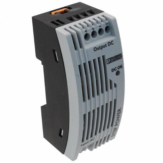
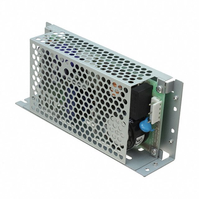
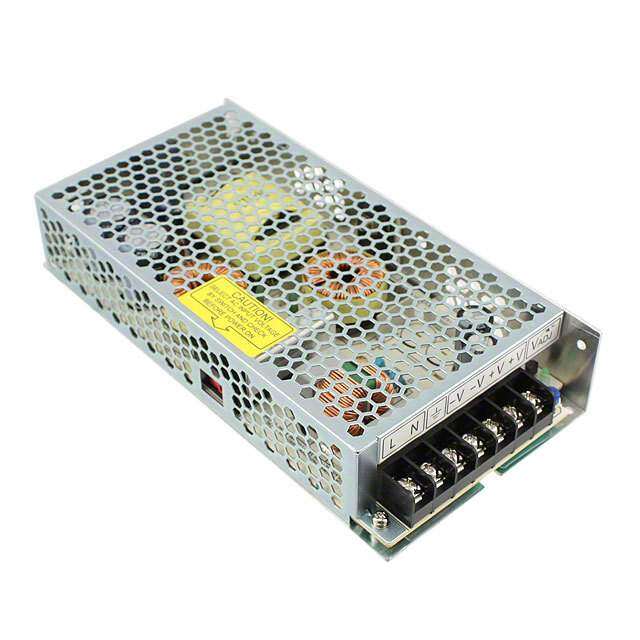
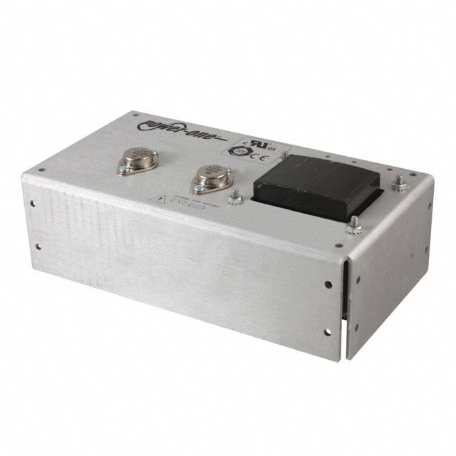
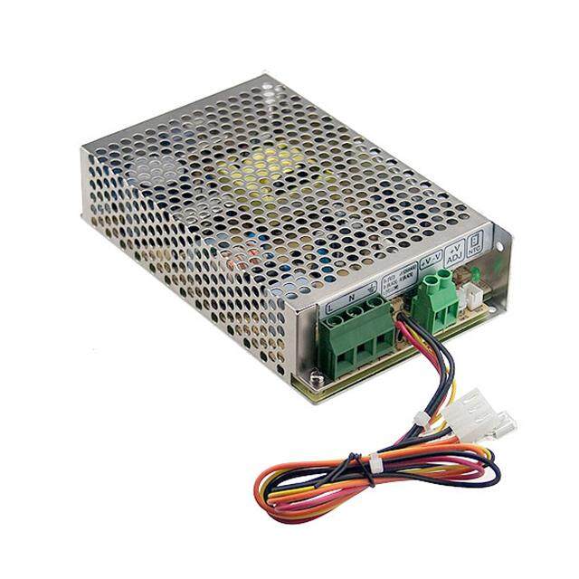
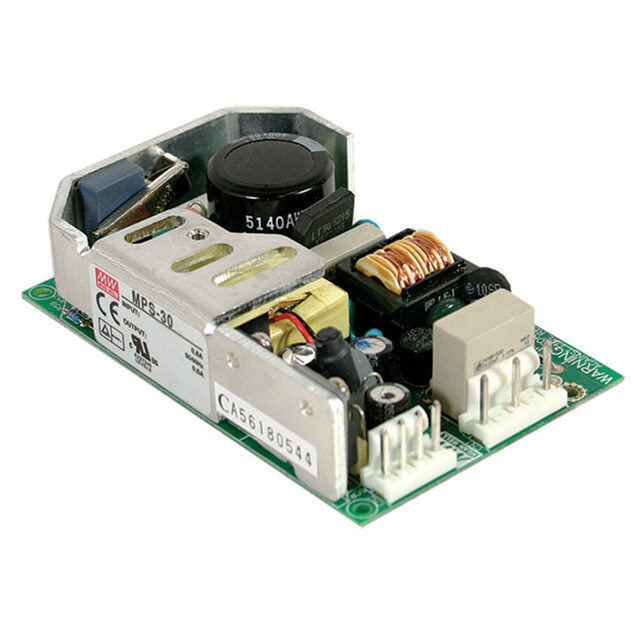
ICGOO电子元器件商城为您提供2868622由Phoenix Contact设计生产,在icgoo商城现货销售,并且可以通过原厂、代理商等渠道进行代购。 2868622价格参考。Phoenix Contact2868622封装/规格:AC DC 转换器, 封闭式 AC DC 转换器 1 输出 24V 500mA 85 ~ 264 VAC 输入。您可以下载2868622参考资料、Datasheet数据手册功能说明书,资料中有2868622 详细功能的应用电路图电压和使用方法及教程。
| 参数 | 数值 |
| 产品目录 | |
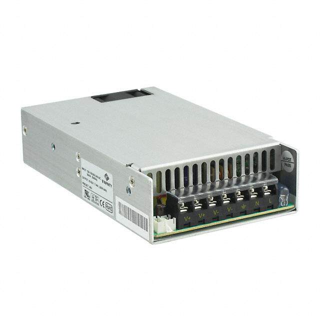
| 描述 | AC/DC CONVERTER 24V 18WDIN导轨式电源 STEP POWER PS/1AC/24DC/0.75/FL |
| 产品分类 | |
| 品牌 | Phoenix Contact |
| 产品手册 | http://www.phoenixcontact.com/gb/products/2868635/pdf |
| 产品图片 |
|
| rohs | 符合RoHS无铅 / 符合限制有害物质指令(RoHS)规范要求 |
| 产品系列 | 电源,DIN导轨式电源,Phoenix Contact 2868622步骤 |
| 数据手册 | |
| 产品型号 | 2868622 |
| 产品 | Switching Supplies |
| 产品种类 | DIN导轨式电源 |
| 其它名称 | 277-6993 |
| 功率(W) | 18W |
| 功率(W)-最大值 | 18W |
| 商标 | Phoenix Contact |
| 商标名 | STEP POWER |
| 商用/医用 | Commercial |
| 大小/尺寸 | 2.40" 长 x 0.71" 宽 x 3.54" 高(61.0mm x 18.0mm x 90.0mm) |
| 安装类型 | DIN 轨道 |
| 安装风格 | DIN Rail |
| 尺寸 | 43 mm L x 36 mm W |
| 工作温度 | -25°C ~ 70°C (有降额) |
| 工厂包装数量 | 1 |
| 应用 | ITE(商业) |
| 开放式框架/封闭式 | Enclosed |
| 所需最小负载 | - |
| 效率 | 81% |
| 标准包装 | 1 |
| 特性 | 可调输出, DC 输入能力, IP20, 负载均分, 通用输入 |
| 电压-输入 | 85 ~ 264 VAC |
| 电压-输出1 | 24V |
| 电压-输出2 | - |
| 电压-输出3 | - |
| 电压-输出4 | - |
| 电压-隔离 | 4kV(4000V) |
| 电流-输出(最大值) | 500mA |
| 类型 | 封闭式 |
| 系列 | STEP-PS |
| 绝缘电压 | 4 kV |
| 认可 | cUL, UR |
| 输入电压 | 85 VAC to 264 VAC, 90 VDC to 250 VDC |
| 输入类型 | 1-Phase / Single Phase |
| 输出功率额定值 | 20 W |
| 输出数 | 1 |
| 输出电压—通道1 | 24 VDC |
| 输出电流—通道1 | 0.83 A |
| 输出端数量 | 1 |
| 零件号别名 | STEP-PS/_1AC/24DC/0.75/FL STEPPS1AC24DC075FL |


- 商务部:美国ITC正式对集成电路等产品启动337调查
- 曝三星4nm工艺存在良率问题 高通将骁龙8 Gen1或转产台积电
- 太阳诱电将投资9.5亿元在常州建新厂生产MLCC 预计2023年完工
- 英特尔发布欧洲新工厂建设计划 深化IDM 2.0 战略
- 台积电先进制程称霸业界 有大客户加持明年业绩稳了
- 达到5530亿美元!SIA预计今年全球半导体销售额将创下新高
- 英特尔拟将自动驾驶子公司Mobileye上市 估值或超500亿美元
- 三星加码芯片和SET,合并消费电子和移动部门,撤换高东真等 CEO
- 三星电子宣布重大人事变动 还合并消费电子和移动部门
- 海关总署:前11个月进口集成电路产品价值2.52万亿元 增长14.8%

PDF Datasheet 数据手册内容提取
STEP-PS/1AC/24DC/0.75/FL Primary-switched power supply for building automation INTERFACE Data sheet 103898_en_00 © PHOENIX CONTACT - 08/2009 1 Description Features STEP POWER power supply units – for building – Easy assembly on the DIN rail or panel automation – Maximum energy efficiency thanks to low idling losses The new STEP POWER generation of compact power supply – Quick startup with LED function monitoring units is particularly suitable for installation distributors and flat – High operating safety due to long mains buffering under control panels thanks to its design. The power supply units full load and high MTBF (> 500,000 h) are available with 24VDC output voltage in four performance classes and widths and with the special voltages 5, 12, 15 – Can be used worldwide in all industrial sectors due to a and 48VDC. Their high degree of efficiency and the low wide-range input and an international approval package standby losses make for high power efficiency. – Wide temperature range of -25°C to +70°C – Parallel connection possible for increased performance and redundancy – Extra flat type for mounting on DIN rails or horizontal DANGER OF EXPLOSION! Only remove equipment when it is disconnected and not in the potentially explosive area. DANGER The device contains dangerous live elements and high levels of stored energy. Never carry out work when the power is turned on. Make sure you always use the latest documentation. It can be downloaded at www.phoenixcontact.net/download
STEP-PS/1AC/24DC/0.75/FL 2 Table of contents 1 Description..................................................................................................................................1 Features.....................................................................................................................................................................1 2 Table of contents.........................................................................................................................2 3 Ordering data..............................................................................................................................3 4 Technical data.............................................................................................................................3 5 Structure......................................................................................................................................6 6 Block diagram.............................................................................................................................7 7 Safety notes................................................................................................................................7 8 Installation...................................................................................................................................8 9 Installation position......................................................................................................................8 10 Mounting on DIN rails..................................................................................................................9 Assembly...................................................................................................................................................................9 Removing...................................................................................................................................................................9 11 Connection to various systems....................................................................................................9 12 Input..........................................................................................................................................10 Protection of the primary side...................................................................................................................................10 Recommended backup fuse for mains protection....................................................................................................10 13 Output.......................................................................................................................................10 Protection of the secondary side..............................................................................................................................10 14 Signaling...................................................................................................................................11 15 Function....................................................................................................................................11 Output characteristic curve......................................................................................................................................11 Thermal behavior.....................................................................................................................................................12 Parallel operation.....................................................................................................................................................12 Redundant operation...............................................................................................................................................12 Increased performance............................................................................................................................................13 103898_en_00 PHOENIX CONTACT 2
STEP-PS/1AC/24DC/0.75/FL 3 Ordering data Description Type Order No. Pcs. / Pkt. DIN rail power supply unit 24 V DC/0.75 A, primary switched-mode, 1- STEP-PS/1AC/24DC/0.75/FL 2868622 1 phase, 43 mm constructional depth. 4 Technical data Input data Input nominal voltage range 100 V AC ... 240 V AC AC input voltage range 85 V AC ... 264 V AC DC input voltage range 95 V DC ... 250 V DC AC frequency range 45 Hz ... 65 Hz DC frequency range 0 Hz Current consumption Approx. 0.37 A (120 V AC) Approx. 0.25 A (230 V AC) Inrush current limitation < 15 A (typical) I2t < 0.1 A2s Power failure bypass > 15 ms (120 V AC) > 70 ms (230 V AC) Typical response time < 0.5 s Protective circuitry Transient surge protection Varistor Input fuse, integrated 1.25 A (slow-blow, internal) Recommended backup fuse for mains protection 6 A (Characteristic B) 10 A (characteristic B) 16 A (characteristic B) Output data Nominal output voltage 24 V DC ±1% Output current 0.75 A (-25°C ... 70°C) 0.83 A (-25 °C ... 40 °C permanent) 1.4 A (maximum output current) Derating Above +55°C: 2.5% per Kelvin Control deviation < 1 % (change in load, static 10% ... 90%) < 2 % (change in load, dynamic 10% ... 90%) < 0.1 % (change in input voltage ±10%) Efficiency > 84 % (for 230 V AC and nominal values) Ascent time < 0.5 s (U (10% ... 90%)) OUT Residual ripple < 75 mV (with nominal values) PP Peak switching voltages < 75 mV (with nominal values) PP Connection in parallel Yes, for redundancy and increased capacity Connection in series Yes Surge protection against internal surge voltages Yes, limited to approx. 35 V DC Resistance to reverse feed max. 35 V DC LED status indicator Status display "DC OK" LED green / UOUT > 21.5 V: LED lights up 103898_en_00 PHOENIX CONTACT 3
STEP-PS/1AC/24DC/0.75/FL General data Insulation voltage input/output 4 kV AC (type test) 2 kV AC (routine test) Insulation voltage input / PE 3.5 kV AC (type test) 2 kV AC (routine test) Insulation voltage output / PE 500 V DC (routine test) Degree of protection IP20 Class of protection II MTBF > 500 000 h in acc. with IEC 61709 (SN 29500) Housing material polycarbonate Foot latch material Plastic POM Dimensions W / H / D (state of delivery) 36 mm / 90 mm / 43 mm Weight 0.1 kg Ambient conditions Ambient temperature (operation) -25 °C ... 70 °C (> 55° C derating) Ambient temperature (storage/transport) -40 °C ... 85 °C Max. permissible relative humidity (operation) 95 % (at 25 °C, no condensation) Vibration (operation) < 15 Hz, amplitude ±2.5 mm in acc. with IEC 60068-2-6 15 Hz ... 150 Hz, 2.3g, 90 min. Shock 30g in all directions in acc. with IEC 60068-2-27 Pollution degree in acc. with EN 50178 2 Climatic class 3K3 (in acc. with EN 60721) Standards Electrical Equipment for Machinery EN 60204 Safety transformers for power supply units IEC 61558-2-17 Electrical safety (of information technology equipment) IEC 60950/VDE 0805 (SELV) Electronic equipment for use in electrical power installations EN 50178/VDE 0160 (PELV) SELV IEC 60950 (SELV) and EN 60204 (PELV) Safe isolation DIN VDE 0100-410 DIN VDE 0106-1010 Protection against electric shock DIN 57100-410 Protection against electric shock, basic requirements for safe isolation in DIN VDE 0106-101 electrical equipment Limitation of mains harmonic currents EN 61000-3-2 Certificate CB Scheme Approvals UL approvals UL/C-UL listed UL 508 UL/C-UL Recognized UL 60950 NEC Class 2 as per UL 1310 103898_en_00 PHOENIX CONTACT 4
STEP-PS/1AC/24DC/0.75/FL Conformance with EMC guideline 2004/108/EC and for low-voltage guideline 2006/95/EC Noise immunity according to EN 61000-6-2 Electrostatic discharge EN 61000-4-2 Housing Level 3 Contact discharge ± 6 kV (Contact discharge) Discharge in air ± 8 kV (Air discharge) Comments Criterion B Electromagnetic HF field EN 61000-4-3 Housing Level 4 Frequency range 80 MHz ... 3000 MHz Field intensity 10 V/m Comments Criterion A Fast transients (burst) EN 61000-4-4 Input 4 kV (level 4 - asymmetrical) Output 2 kV (Level 3 - asymmetrical) Comments Criterion B Surge current loads (surge) EN 61000-4-5 Input 4 kV (asymmetrical: Conductor to ground) 2 kV (symmetrical: Conductor to conductor) Output 2 kV (level 3 - asymmetrical: conductor to ground) 1 kV (Level 3 - symmetrical: Conductor to conductor) Comments Criterion B Conducted interference EN 61000-4-6 Input/output Level 3 - asymmetrical Frequency range 10 kHz ... 80 MHz Voltage 10 V Comments Criterion A Voltage dips EN 61000-4-11 Input (mains buffering > 20 ms) Comments Criterion A Emitted interference in acc. with EN 61000-6-3 Radio interference voltage in acc. with EN 55011 EN 55011 (EN 55022) class B used in industry and residential area / EMC 1 Emitted radio interference in acc. with EN 55011 EN 55011 (EN 55022) class B used in industry and residential area / EMC 1 103898_en_00 PHOENIX CONTACT 5
STEP-PS/1AC/24DC/0.75/FL 5 Structure 1 AC input 4 2 DC output 3 "DC OK" LED 2 4 Universal snap-on foot for EN DIN rails and for wall mounting OutputDC DCOK 3 InputAC 1 [mm2] AWG [Nm] solid stranded Torque Input 0.2-2.5 0.2-2.5 24-12 0.6-0.8 Output 0.2-2.5 0.2-2.5 24-12 0.6-0.8 Input data Input nominal voltage range 100 V AC ... 240 V AC AC input voltage range 85 V AC ... 264 V AC DC input voltage range 95 V DC ... 250 V DC AC frequency range 45 Hz ... 65 Hz DC frequency range 0 Hz Input fuse, integrated 1.25 A (slow-blow, internal) Recommended backup fuse for mains protection 6 A (Characteristic B) 10 A (characteristic B) 16 A (characteristic B) Type of connection Screw connection Stripping length 6.5 mm Output data Nominal output voltage 24 V DC ±1% Output current 0.75 A (-25°C ... 70°C) 0.83 A (-25 °C ... 40 °C permanent) 1.4 A (maximum output current) Type of connection Screw connection Stripping length 6.5 mm 103898_en_00 PHOENIX CONTACT 6
STEP-PS/1AC/24DC/0.75/FL 6 Block diagram + L(+) + N(-) – – 7 Safety notes DANGER OF EXPLOSION! Only remove equipment when it is disconnected and not in the potentially explosive area. DANGER The device contains dangerous live elements and high levels of stored energy. Never carry out work when the power is turned on. WARNING Before startup please ensure: The mains connection has been carried out by a competent person and protection against electric shock is guaranteed! The device can be disconnected outside the power supply unit in accordance with the regulations as in EN 60950 (e.g. through primary side line protection)! All feed lines are sufficiently protected and dimensioned! All output lines are dimensioned according to the maximum output current of the device or separately protected! Sufficient convection is guaranteed! CAUTION The power supply units are built-in devices. The device may only be installed and put into operation by qualified personnel. The corresponding national regulations must be observed. 103898_en_00 PHOENIX CONTACT 7
STEP-PS/1AC/24DC/0.75/FL 8 Installation ATTENTION In order to ensure sufficient convection, we recommend a minimum vertical distance of 30 mm to the other devices. OutputDC The power supply unit can be snapped onto all DIN rails as per EN 60715; it can also be DCOK mounted on walls. The device must be mounted vertically (connecting terminals above or below). InputAC 9 Installation position 36 43 37 0 3 OutputDC DCOK 150 90 InputAC 0 3 103898_en_00 PHOENIX CONTACT 8
STEP-PS/1AC/24DC/0.75/FL 10 Mounting on DIN rails Assembly To mount on an EN DIN rail, snap the device straight onto the DIN rail. If the power supply unit is to be fastened directly onto an even surface, press the orange base latch upward and down. Place a washer between the pulled-out base latch and the even surface (max. outer diameter 8.5 mm, max. thickness 1.3 mm, e.g., spring washer for M4 in acc. with DIN 127-B or toothed lock washer in acc. with DIN 6797). Then fasten the device with two screws (max. thread diameter 4 mm, max. head diameter 8.5 mm). Removing To dismantle from the EN DIN rail, press the orange base latch outward and pull the device off of the DIN rail. In the case of wall mounting, loosen the screws and press the base latch inwards again. 11 Connection to various systems TN-S TN-C TT iT L1 L L L L2 N PEN N L3 PE L N L N L N L N + - + - + - + - The 100 V AC ... 240 V AC connection is made using the L and N screw connections. The device can be connected to 1-phase AC networks or to two of the phase conductors of three-phase systems (TN, TT or IT networks in acc. with VDE 0100-300/IEC 60364-3) with nominal voltages of 100 V AC ...240 V AC. For operation on two of the phase conductors of a three-phase system, an isolating facility for all poles must be provided. 103898_en_00 PHOENIX CONTACT 9
STEP-PS/1AC/24DC/0.75/FL 12 Input CAUTION If an internal fuse is triggered, there is most probably a malfunction in the device. In this case, the device must be inspected in the factory! OutputDC Protection of the primary side The device must be installed in acc. with the regulations as in DCOK EN 60950. It must be possible to disconnect the device using a suitable isolating facility outside the power supply. The primary side line protection, for example, is suitable. For device protection, there is an internal fuse. Additional device InputAC protection is not necessary. Recommended backup fuse for mains protection Power circuit-breaker 6 A, 10 A or 16 A, characteristic B (or identical function). Connect a suitable fuse upstream for DC applications! 13 Output CAUTION Make sure that all output lines are dimensioned according to the maximum output current or are separately protected. The cables on the secondary side must have sufficiently large cross sections in order to keep the voltage OutputDC drops on the lines as low as possible. The connection is made using the "+" and "-" screw DCOK connections on the screw connection of the DC output. The set output voltage is 24 V DC at the time of delivery. Protection of the secondary side InputAC The device is electronically protected against short circuit and idling. In the event of a malfunction, the output voltage is limited to 35 V DC. 103898_en_00 PHOENIX CONTACT 10
STEP-PS/1AC/24DC/0.75/FL 14 Signaling The "DC OK" LED enables evaluation of the function of the power supply directly on site. State 1 State 2 "DC OK" LED ON OFF Cause Output voltage >21.5V Output voltage <21,5V or no voltage at the output Meaning Output voltage and output The device is in operation, but there is a fault in the current OK consumer, the current consumption is greater than I or the 1 output is short circuited. The device is out of operation because there is no mains voltage, the fuse on the primary side has been triggered, or the device is faulty. 15 Function Output characteristic curve V] P P The power supply works with a power reserve as shown in the [ N 1 T U/I characteristic curve in the figure. At ambient temperatures U UO UN TAMB<+40°C, I1 is available continuously. At higher temperatures, it's available for a few minutes. In the event of a secondary-side short circuit or overload, the output current is limited to I . Thereby, the module does not switch off, but MAX rather supplies a continuous output current. The secondary voltage is reduced here until the short circuit is eliminated. I I I The U/I characteristic curve with the power reserve ensures N 1 MAX I [A] that both high inrush currents of capacitive loads as well as OUT consumers with DC/DC converters in the primary circuit can be supplied. U = 24 V N I = 0.75 A N P = 18 W N I = 0.83 A 1 P = 19.8 W 1 I = 1.4 A (U = 0 V) MAX OUT 103898_en_00 PHOENIX CONTACT 11
STEP-PS/1AC/24DC/0.75/FL Thermal behavior A] With an ambient temperature of up to +55°C, the device [ ent supplies the continuous output current of IN. In the case of urr IN ambient temperatures above +55°C, the output current must c be reduced by 2.5% per Kelvin increase in temperature. The ut p device does not switch off at ambient temperatures of +70°C ut O or thermal overload. The output capacity is reduced as far as necessary to provide device protection. After it has cooled 0 down, the output capacity is increased again. -25 20 40 60 Ambienttemperature[°C] Parallel operation Devices of the same type can be connected in parallel to enable both redundancy and an increase in efficiency. No other alignment is necessary when in the state of delivery. To ensure symmetrical distribution of power, we recommend designing all cable connections from the power supply unit to a busbar of the same length and with the same conductor cross section. The system makes it advisable to install a protective circuit at the output of each device when more than two power supply units are connected in parallel (e.g. decoupling diode or DC fuse). This prevents high reverse feed currents in the event of a secondary device fault. Redundant operation I I N N Redundant circuits are suitable for the supply of systems + − + − which make especially high requirements on the operational safety. If a fault occurs in the primary circuit of the first power supply unit, the second device automatically takes over the entire power supply, without interruption, and vice versa. For + this reason, the power supply units to be connected in parallel − are dimensioned in such a way that the total current requirement of all consumers can be completely covered by one power supply unit. 100% redundancy makes external decoupling diodes necessary (QUINT-DIODE/40, Order No. Σ= I N 2938963)! + − 103898_en_00 PHOENIX CONTACT 12
STEP-PS/1AC/24DC/0.75/FL Increased performance I I N N For n parallel connected devices, the output current can be + − + − increased to n x I . Parallel connection to increase efficiency N is used for the expansion of existing systems. It is advisable to use parallel connection if the power supply unit does not cover the current requirement of the most powerful + consumer. Otherwise the consumers should be spread − among individual devices independent of one another. A maximum of five devices can be connected in parallel! Σ= 2 x I N + − 103898_en_00 PHOENIX CONTACT GmbH & Co. KG • 32823 Blomberg • Germany • Phone: +49-(0) 5235-3-00 13 PHOENIX CONTACT • P.O.Box 4100 • Harrisburg • PA 17111-0100 • USA • Phone: +717-944-1300 www.phoenixcontact.com