ICGOO在线商城 > 射频/IF 和 RFID > RF 天线 > 2450AT43A100E
- 型号: 2450AT43A100E
- 制造商: Johanson Dielectrics Inc.
- 库位|库存: xxxx|xxxx
- 要求:
| 数量阶梯 | 香港交货 | 国内含税 |
| +xxxx | $xxxx | ¥xxxx |
查看当月历史价格
查看今年历史价格
2450AT43A100E产品简介:
ICGOO电子元器件商城为您提供2450AT43A100E由Johanson Dielectrics Inc.设计生产,在icgoo商城现货销售,并且可以通过原厂、代理商等渠道进行代购。 2450AT43A100E价格参考¥0.59-¥0.59。Johanson Dielectrics Inc.2450AT43A100E封装/规格:RF 天线, 2.4GHz 芯片 RF 天线 2.4GHz ~ 2.5GHz 2dBi 焊接 表面贴装。您可以下载2450AT43A100E参考资料、Datasheet数据手册功能说明书,资料中有2450AT43A100E 详细功能的应用电路图电压和使用方法及教程。
Johanson Technology Inc. 的2450AT43A100E是一款RF(射频)天线,主要应用于2.45 GHz频段的无线通信系统。这款天线具有较高的增益和良好的方向性,适用于多种应用场景,尤其是在需要高效传输和接收射频信号的环境中。以下是该型号天线的主要应用场景:

1. 物联网(IoT)设备:2450AT43A100E广泛应用于物联网设备中,如智能家居、智能城市、工业自动化等。它能够确保设备之间的稳定通信,特别是在需要长距离传输或高数据速率的情况下。

2. 无线传感器网络(WSN):在无线传感器网络中,这款天线可以用于环境监测、物流跟踪、健康监护等领域。其高效的射频性能有助于提高数据传输的可靠性和准确性。

3. 医疗设备:在医疗领域,2450AT43A100E可用于无线医疗设备,如可穿戴健康监测设备、远程医疗系统等。它能够确保患者数据的实时传输,支持医生进行远程诊断和治疗。

4. 无线充电系统:该天线也适用于无线充电系统,特别是在需要高效能量传输的应用中。它可以优化电磁波的发射和接收,提高充电效率并减少能量损耗。

5. 无人机和无人飞行器(UAV):在无人机和无人飞行器中,2450AT43A100E可以用于数据链路通信,确保飞行器与地面站之间的稳定连接。其良好的方向性和增益特性有助于扩展通信范围并提高数据传输质量。

6. 无线音频和视频传输:在无线音频和视频传输设备中,这款天线可以提供稳定的射频信号传输,确保高质量的音视频流。它适用于会议系统、广播设备、监控摄像头等场景。

7. 工业自动化和机器人:在工业自动化和机器人应用中,2450AT43A100E可以用于无线控制和数据采集,确保生产设备之间的高效通信。它能够适应复杂的工业环境,提供可靠的射频性能。

总之,Johanson Technology Inc. 的2450AT43A100E天线凭借其优异的射频性能和广泛的适用性,在多个领域展现了重要的应用价值。
| 参数 | 数值 |
| 产品目录 | |
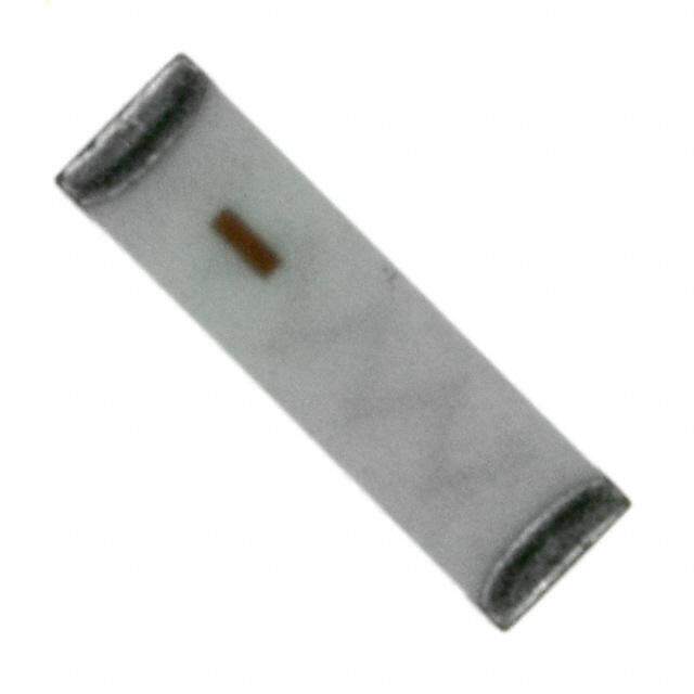
| 描述 | ANTENNA CHIP 2.4GHZ天线 2.45GHz SMD ANTENNA |
| 产品分类 | |
| 品牌 | Johanson Technology Inc |
| 产品手册 | |
| 产品图片 |
|
| rohs | 符合RoHS不受无铅要求限制 / 符合限制有害物质指令(RoHS)规范要求 |
| 产品系列 | Johanson Technology 2450AT43A100E- |
| 数据手册 | |
| 产品型号 | 2450AT43A100E |
| VSWR | - |
| 产品培训模块 | http://www.digikey.cn/PTM/IndividualPTM.page?site=cn&lang=zhs&ptm=10258 |
| 产品目录页面 | |
| 产品种类 | 天线 |
| 其它名称 | 2450AT43A100 |
| 功率额定值 | 2 W |
| 包装 | 带卷 (TR) |
| 商标 | Johanson Technology |
| 增益 | 0.5dBi |
| 天线类型 | 芯片 |
| 安装类型 | 表面贴装 |
| 安装风格 | SMD/SMT |
| 宽度 | 2 mm |
| 封装 | Reel |
| 尺寸 | 7 mm L x 2 mm W x 1.2 mm H |
| 工厂包装数量 | 1000 |
| 技术类型 | Internal SMD Chip Antenna |
| 标准包装 | 1,000 |
| 特色产品 | http://www.digikey.com/cn/zh/ph/Johanson/IntegratedPassives.html |
| 端接 | 表面贴装型 |
| 端接类型 | SMD/SMT |
| 系列 | 2450AT |
| 长度 | 7 mm |
| 阻抗 | 50 Ohms |
| 频带数 | 1 |
| 频率 | 2.4GHz ~ 2.5GHz |
| 频率范围 | 2.4 GHz to 2.5 GHz |
| 高度 | 1.2 mm |
| 高度(最大值) | 0.047"(1.20mm) |


- 商务部:美国ITC正式对集成电路等产品启动337调查
- 曝三星4nm工艺存在良率问题 高通将骁龙8 Gen1或转产台积电
- 太阳诱电将投资9.5亿元在常州建新厂生产MLCC 预计2023年完工
- 英特尔发布欧洲新工厂建设计划 深化IDM 2.0 战略
- 台积电先进制程称霸业界 有大客户加持明年业绩稳了
- 达到5530亿美元!SIA预计今年全球半导体销售额将创下新高
- 英特尔拟将自动驾驶子公司Mobileye上市 估值或超500亿美元
- 三星加码芯片和SET,合并消费电子和移动部门,撤换高东真等 CEO
- 三星电子宣布重大人事变动 还合并消费电子和移动部门
- 海关总署:前11个月进口集成电路产品价值2.52万亿元 增长14.8%
PDF Datasheet 数据手册内容提取
High Frequency Ceramic Solutions 2.45 GHz SMD Chip Antenna P/N 2450AT43A100 Detail Specification: 1/11/2013 Page 1 of 6 General Specifications - Vertical Mounting Part Number 2450AT43A100 Input Power 2W max. Frequency Range 2400 - 2500 Mhz Impedance 50 Ω Peak Gain 2.0 dBi typ. (XZ-V) Operating Temperature -40 to +85°C Average Gain 0.5 dBi typ. (XZ-V) Reel Quanity 1,000 Return Loss 9.5 dB min. Part Number Explanation Bulk Suffix = S eg. 2450AT43A100S Packing Style T & R Suffix = E eg. 2450AT43A100E P/N Suffix 100% Tin Suffix = None eg. 2450AT43A100 (E or S) Termination style Tin / Lead Please Consult Factory Mechanical Dimensions Terminal Configuration In mm No. Function L 0.276 ± 0.008 7.00 ± 0.20 1 Signal Feed Terminal W 0.079 ± 0.008 2.00 ± 0.20 2 NC (To be used as Anchoring to PCB) T 0.047 + .004/-.008 1.20 + 0.1/-0.2 a 0.020 ± 0.012 0.50 ± 0.30 a 2 1 W T L Mounting Considerations - Vertical Mounting Mount these devices with brown mark facing up. Units: mm * Line width should be designed to provide 50 Ω impedance matching characteristics. 1.0 8.0 GND Plane 5.5 * 0 2.0 GND Plane Note: Matching components may be needed when designing into a PCB so, make sure to leave a shunt-series- shunt or "pi" network available space/footprint when laying out. More info: http://johansontechnology.com/tuning Johanson Technology, Inc. reserves the right to make design changes without notice. All sales are subject to Johanson Technology, Inc. terms and conditions. www.johansontechnology.com 4001 Calle Tecate • Camarillo, CA 93012 • TEL 805.389.1166 FAX 805.389.1821 Ver 1.1 2012 Johanson Technology, Inc. All Rights Reserved
High Frequency Ceramic Solutions 2.45 GHz SMD Chip Antenna P/N 2450AT43A100 Detail Specification: 1/11/2013 Page 2 of 6 Typical Electrical Characteristics (T=25°C) Test Board of Vertical Mounting style, p/n: 2450AT43A100-EB1SMA 40mm 9.5m ) 50Ω Feed Line 40mm ) 20mm 0Ω Antenna Ground 19mm No Ground * This 50ohm trace to the antenna can be shorten (considerably) to suit your PCB space constraints Return Loss ) Johanson Technology, Inc. reserves the right to make design changes without notice. All sales are subject to Johanson Technology, Inc. terms and conditions. www.johansontechnology.com 4001 Calle Tecate • Camarillo, CA 93012 • TEL 805.389.1166 FAX 805.389.1821 Ver 1.1 2012 Johanson Technology, Inc. All Rights Reserved
High Frequency Ceramic Solutions 2.45 GHz SMD Chip Antenna P/N 2450AT43A100 Detail Specification: 1/11/2013 Page 3 or 6 Typical Electrical Characteristics (T=25°C) Typical Radiation Patterns on Test Board of Vertical Mounting p/n: 2450AT43A100-EB1SMA XY cut @2.45GHz Vertical XY-V/XY-H Z Horizontal 180° X 90° 270° Y 0° XY-cut scanning direction XZ-V/XZ-H XZ cut @2.45GHz Y Vertical Horizontal 180° X 90° 2 70° Z 0° XZ-cut scanning direction ) YZ cut @2.45GHz YZ-V/YZ-H X Vertical Horizontal 180° Y 90° 2 70° Z 0° YZ-cut scanning direction Johanson Technology, Inc. reserves the right to make design changes without notice. All sales are subject to Johanson Technology, Inc. terms and conditions. www.johansontechnology.com 4001 Calle Tecate • Camarillo, CA 93012 • TEL 805.389.1166 FAX 805.389.1821 Ver 1.1 2012 Johanson Technology, Inc. All Rights Reserved
High Frequency Ceramic Solutions 2.45 GHz SMD Chip Antenna P/N 2450AT43A100 Detail Specification: 1/11/2013 Page 4 of 6 General Specifications - Horizontal Mounting Part Number 2450AT43A100 Input Power 2W max. Frequency Range 2400 - 2500 Mhz Impedance 50 Ω Peak Gain 2.0 dBi typ. (XZ-V) Operating Temperature -40 to +85°C Average Gain 1.0 dBi typ. (XZ-V) Reel Quanity 1,000 Return Loss 9.5 dB min. Mounting Considerations - Horizontal Mounting Mount these devices with brown mark facing up. Units: mm * Line width should be designed to provide 50 Ω impedance matching characteristics. 1.0 8.0 5.5 GND 6.8 2.0 0 Ohm * GND Note: Matching components might be needed when design into a PCB so, make sure to leave a shunt-series- shunt or "pi" network available space/footprint when laying out. More info: http://johansontechnology.com/tuning Johanson Technology, Inc. reserves the right to make design changes without notice. All sales are subject to Johanson Technology, Inc. terms and conditions. www.johansontechnology.com 4001 Calle Tecate • Camarillo, CA 93012 • TEL 805.389.1166 FAX 805.389.1821 Ver 1.1 2012 Johanson Technology, Inc. All Rights Reserved
High Frequency Ceramic Solutions 2.45 GHz SMD Chip Antenna P/N 2450AT43A100 Detail Specification: 1/11/2013 Page 5 of 6 Typical Electrical Characteristics (T=25°C) Test Board of Horizontal Mounting style, p/n: 2450AT43A100-EB2SMA 50Ω Feed Ground 40mm Trace (CPWG) Matching Circuit 20mm 9mm 40mm 5mm 2.5mm No Ground 9.5mm * This 50ohm trace to the antenna can be shorten (considerably) to suit your PCB space constraints Return Loss ) Johanson Technology, Inc. reserves the right to make design changes without notice. All sales are subject to Johanson Technology, Inc. terms and conditions. www.johansontechnology.com 4001 Calle Tecate • Camarillo, CA 93012 • TEL 805.389.1166 FAX 805.389.1821 Ver 1.1 2012 Johanson Technology, Inc. All Rights Reserved
High Frequency Ceramic Solutions 2.45 GHz SMD Chip Antenna P/N 2450AT43A100 Detail Specification: 1/11/2013 Page 6 or 6 Typical Electrical Characteristics (T=25°C) Typical Radiation Patterns on Test Board of Vertical Mounting p/n: 2450AT43A100-EB2SMA XY cut @2.45GHz Vertical XY-V/XY-H Z Horizontal 180° X 90° 270° Y 0° XY-cut scanning direction XZ-V/XZ-H XZ cut @2.45GHz Y Vertical Horizontal 180° X 90° 2 70° 0° Z XZ-cut scanning direction ) YZ cut @2.45GHz YZ-V/YZ-H X Vertical Horizontal 180° Y 90° 2 70° Z 0° YZ-cut scanning direction Johanson Technology, Inc. reserves the right to make design changes without notice. All sales are subject to Johanson Technology, Inc. terms and conditions. www.johansontechnology.com 4001 Calle Tecate • Camarillo, CA 93012 • TEL 805.389.1166 FAX 805.389.1821 Ver 1.1 2012 Johanson Technology, Inc. All Rights Reserved
Mouser Electronics Authorized Distributor Click to View Pricing, Inventory, Delivery & Lifecycle Information: J ohanson: 2450AT43A100E

 Datasheet下载


