ICGOO在线商城 > Labels, Signs, Barriers, Identification > Accessories > 20C250
- 型号: 20C250
- 制造商: CORCOM/TYCO ELECTRONICS
- 库位|库存: xxxx|xxxx
- 要求:
| 数量阶梯 | 香港交货 | 国内含税 |
| +xxxx | $xxxx | ¥xxxx |
查看当月历史价格
查看今年历史价格
20C250产品简介:
ICGOO电子元器件商城为您提供20C250由CORCOM/TYCO ELECTRONICS设计生产,在icgoo商城现货销售,并且可以通过原厂、代理商等渠道进行代购。 20C250价格参考¥2.64-¥4.18。CORCOM/TYCO ELECTRONICS20C250封装/规格:Accessories, Clip, Hold Down R10 Series。您可以下载20C250参考资料、Datasheet数据手册功能说明书,资料中有20C250 详细功能的应用电路图电压和使用方法及教程。
| 参数 | 数值 |
| 产品目录 | |
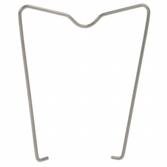
| 描述 | R10 WIRE HOLD DOWN SPRING 4 POLE继电器插座与硬件 R10 HOLD DOWN SPRING |
| 产品分类 | |
| 品牌 | TE Connectivity / P&B |
| 产品手册 | |
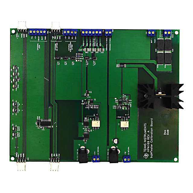
| 产品图片 |
|
| rohs | 符合RoHS无铅 / 符合限制有害物质指令(RoHS)规范要求 |
| 产品系列 | 继电器插座与硬件,TE Connectivity / P&B 20C250R10,Potter & Brumfield |
| 数据手册 | |
| 产品型号 | 20C250 |
| 产品目录页面 | |
| 产品种类 | 继电器插座与硬件 |
| 其它名称 | 20C250BULK |
| 商标 | TE Connectivity / P&B |
| 工厂包装数量 | 25 |
| 标准包装 | 25 |
| 特色产品 | http://www.digikey.com/cn/zh/ph/te/relays.html |
| 相关继电器系列 | R10 |
| 端接类型 | Solder |
| 规格 | - |
| 配件类型 | 夹,压紧 |
| 配套使用产品/相关产品 | R10 系列 |
| 配用 | /product-detail/zh/27E213/PB806-ND/1095147/product-detail/zh/27E194/PB804-ND/1095146/product-detail/zh/27E163/PB802-ND/1095145/product-detail/zh/27E629/27E629-ND/299800/product-detail/zh/27E461/PB674-ND/259609/product-detail/zh/27E129/PB135-ND/44963/product-detail/zh/27E126/PB133-ND/44959 |
| 附件类型 | Hold Down Spring |
| 零件号别名 | 3-1393159-6 |
| 颜色 | - |







- 商务部:美国ITC正式对集成电路等产品启动337调查
- 曝三星4nm工艺存在良率问题 高通将骁龙8 Gen1或转产台积电
- 太阳诱电将投资9.5亿元在常州建新厂生产MLCC 预计2023年完工
- 英特尔发布欧洲新工厂建设计划 深化IDM 2.0 战略
- 台积电先进制程称霸业界 有大客户加持明年业绩稳了
- 达到5530亿美元!SIA预计今年全球半导体销售额将创下新高
- 英特尔拟将自动驾驶子公司Mobileye上市 估值或超500亿美元
- 三星加码芯片和SET,合并消费电子和移动部门,撤换高东真等 CEO
- 三星电子宣布重大人事变动 还合并消费电子和移动部门
- 海关总署:前11个月进口集成电路产品价值2.52万亿元 增长14.8%
PDF Datasheet 数据手册内容提取
Signal Signal Relays Potter & Brumfield R10 Series Relay n 1 through 8 form C (CO) contact arrangement n Broad range of coil options provides sensitivity ranging from 25 to 750mW n Various contacts switch from dry circuit to 7.5 amps n Many mounting and termination options Typical applications R10 R10-R R10S R10-T Coin changers, audio equipment, elevators, traffic controls, ultrasonic test equipment, parking toll readers. Approvals Contact ratings (continued) UL E29244; CSA LR15734 Type Load Cycles Technical data of approved types on request. UL 508 P type, Au overlay Ag, bifurcated crossbar contact Contact Data 2A, 120VAC, resistive 100x103 Contact arrangement 1, 2, 3, 4, 6 and 8 form C (CO) 3 A, 120 VAC, resistive 6x10³ Rated voltage 120VAC 3 A, 30 VDC, resistive 100x103 Rated current 7.5A L type, AuPtAg, bifurcated crossbar contact Contact material Ag, AgCdO, Au overlay Ag, AuPtAg 500mA, 28VDC, resistive 6x10³ Contact style Single or bifurcated crossbar Mechanical endurance 10x106 ops., except W type is 1x10⁶ ops. Min. recommended contact load W type, AgCdO, single contact 300mA, 12VDC X type, AgCdO, single contact 300mA, 12VDC Coil Data M type, AgCdO, bifurcated contact 300mA, 12VDC Coil voltage range 3 to 115VDC Y type, Ag, single contact 100mA, 12VDC 4.5mA to 20mA Z type, Ag, bifurcated crossbar 1mA, 12VDC 6 to 115VAC P type, Au overlay Ag, bifurcated crossbar dry circuit Coil versions, DC coil L type, AuPtAg, bifurcated crossbar dry circuit Coil Rated Operate Coil Rated coil Initial contact resistance code voltage voltage resistance power All AgCdO contact types 100mΩ VDC VDC Ω±10% mW All other contact materials and types 50mΩ V - standard DC voltage adjustment Frequency of operation 360 ops./hr 1, 2 and 4 pole V10 3 2.25 10 900 Contact ratings V28 5 3.75 28 900 Type Load Cycles V52 6 4.5 52 900 UL 508 V185 12 9 185 900 W type, AgCdO, single contact V700 24 18 700 900 7.5A, 120VAC, resistive V2.5K 48 36 2500 900 7.5A, 28VDC, resistive V5.8K 72 54 5800 900 1/8HP, 120VAC, same polarity V15.0K 115 86 15000 900 1/6HP, 240VAC, same polarity 6 pole X type, AgCdO, single contact V6 3 2.25 6 1,500 2A, 30VDC, resistive 100x103 V16 5 3.75 16 1,600 5A, 120VAC, resistive 6x10³ V25 6 4.5 25 1,500 5A, 30VDC, resistive 100x103 V90 12 9 90 1,600 1/20HP, 120VAC, same polarity V430 24 18 430 1,400 1/10HP, 240VAC, same polarity V1.5K 48 36 1500 1,600 M type, AgCdO, bifurcated contact V3.5K 72 54 3500 1,500 5A, 120VAC, resistive 6x10³ V9.0K 115 86 9000 1,500 5A, 28VDC, resistive 6x10³ 8 pole Y type, Ag, single contact V5 3 2.25 5 1,800 2A, 120VAC 6x10³ V14 5 3.75 14 1,800 2A, 28VDC 6x10³ V20 6 4.5 20 1,800 250VA, 250VAC 30x103 V72 12 9 72 2,000 125VA, 125VAC 100x103 V350 24 18 350 1,700 Z type, Ag, bifurcated crossbar contact V1.25K 48 36 1250 1,900 3A, 120VAC 6x10³ V2.8K 72 54 2800 1,900 3A, 28VDC 6x10³ V8.0K 115 86 8000 1,700 2A, 30VDC 100x103 All figures are given for coil without preenergization, at ambient temperature +23°C. 1 02-2017, Rev. 0217 Datasheets and product specification Datasheets and product data is subject to the Datasheets, product data, ‘Definitions’ sec- www.te.com according to IEC 61810-1 and to be used terms of the disclaimer and all chapters of tion, application notes and all specifications © 2015 Tyco Electronics Corporation, only together with the ‘Definitions’ section. the ‘Definitions’ section, available at are subject to change. a TE Connectivity Ltd. company http://relays.te.com/definitions
Signal Signal Relays Potter & Brumfield R10 Series Relay (Continued) Coil versions, DC coil (continued) Coil versions, DC coil (continued) Coil Rated Operate Coil Rated coil Coil Rated Operate Coil Rated coil code voltage voltage resistance power code voltage voltage resistance power VDC VDC Ω±10% mW VDC VDC Ω±10% mW Q - special DC voltage adjustment S - sensitive DC voltage adjustment (continued) 1 and 2 pole 2 pole Q52 5 3.1 52 500 SS110 3 2.25 110 85 Q110 6 4.5 110 350 SS350 5 3.75 350 75 Q450 12 9.2 450 350 SS500 6 4.5 500 75 Q1.8K 24 17.4 1,800 350 SS2.0K 12 9 2000 75 Q7.5K 48 36.2 7500 310 SS4.5K 18 13.5 4500 75 Q15.0K 72 49.5 15000 350 SS7.5K 24 18 7500 80 Q30.0K 115 67.5 30000 450 SS15.0K 36 27 15000 85 3 and 4 pole SS30.0K 48 36 30000 80 Q32 5 3.8 32 800 3 and 4 pole Q52 6 4.2 52 700 SS52 3 2.25 52 175 Q185 12 8.4 185 800 SS175 5 3.75 175 150 Q1.0K 24 17.2 1000 600 SS250 6 4.5 250 150 Q3.2K 48 31.1 3200 750 SS1.0K 12 9 1000 150 Q7.5K 72 49.3 7500 700 SS2.2K 18 13.5 2200 150 Q15.0K 115 67.5 15000 900 SS3.7K 24 18 3700 150 S - sensitive DC voltage adjustment SS7.5K 36 27 7500 175 1 and 2 pole SS15.0K 48 36 15000 150 S50 3 2.25 50 180 S140 5 3.75 140 180 Coil Maximum Operate Coil Pick-up S200 6 4.5 200 180 code coil current current resistance coil power S800 12 9 800 180 mADC mADC Ω±10% mW S3.2K 24 18 3200 180 J - sensitive DC current adjustment S13.0K 48 36 13000 180 2 pole S28.0K 72 54 28000 190 J1.0K 45 8.5 1000 75 S50.0K 115 86 50000 270 J2.5K 28 5.8 2500 85 3 and 4 pole J5.0K 20 4.1 5000 85 S30 3 2.25 30 300 J10.0K 14 3.1 10000 100 S80 5 3.75 80 350 J15.0K 11.5 2.6 15000 100 S110 6 4.5 110 350 J30.0K 8.3 1.7 30000 85 S450 12 9 450 350 3 and 4 poles S1.8K 24 18 1800 350 J1.0K 45 13 1000 175 S7.5K 48 36 7500 300 J2.5K 28 8.4 2500 175 S16.0K 72 54 16000 350 J5.0K 20 6.2 5000 200 S40.0K 115 86 40000 350 J10.0K 14 4.5 10000 200 6 pole J15.0K 11.5 3.5 15000 200 S20 3 2.25 20 500 J30.0K 8.3 2.5 30000 200 S56 5 3.75 56 500 6 pole S80 6 4.5 80 500 J1.0K 45 16 1000 250 S320 12 9 320 500 J2.5K 28 10 2500 250 S1.2K 24 18 1200 500 J5.0K 20 7.2 5000 250 S5.2K 48 36 5200 500 J10.0K 14 5 10000 250 S13.0K 72 54 13000 400 J15.0K 11.5 4.2 15000 270 S30.0K 115 86 30000 500 J30.0K 8.3 2.9 30000 250 8 pole 8 pole S12 3 2.25 12 750 J1.0K 45 20 1000 250 S35 5 3.75 35 750 J2.5K 28 13 2500 250 S52 6 4.5 52 700 J5.0K 20 9 5000 250 S200 12 9 200 750 J10.0K 14 6.4 10000 250 S800 24 18 800 750 J15.0K 11.5 5.3 15000 270 S3.2K 48 36 3200 750 J30.0K 8.3 3.7 30000 250 S7.5K 72 54 7500 700 J - sensitive DC current adjustment - R10S types only S16.0K 115 86 16000 850 1 pole SS - ultra sensitive DC voltage adjustment J5001) – 4.5 500 10 1 pole J1.0K1) – 3.2 1000 10 SS220 3 2.25 220 45 J2.5K – 2 2500 10 SS700 5 3.75 700 40 J5.0K2) – 1.4 5000 10 SS1.0K 6 4.5 1000 40 J10.0K – 1 10000 10 SS4.0K 12 9 4000 40 J16.0K – 0.8 16000 10 SS9.0K 18 13.5 9000 40 J30.0K3) – 0.6 30000 11 SS15.0K 24 18 15000 40 SS30.0K 36 27 30000 45 2 02-2017, Rev. 0217 Datasheets and product specification Datasheets and product data is subject to the Datasheets, product data, ‘Definitions’ sec- www.te.com according to IEC 61810-1 and to be used terms of the disclaimer and all chapters of tion, application notes and all specifications © 2015 Tyco Electronics Corporation, only together with the ‘Definitions’ section. the ‘Definitions’ section, available at are subject to change. a TE Connectivity Ltd. company http://relays.te.com/definitions
Signal Signal Relays Potter & Brumfield R10 Series Relay (Continued) Operative Range Coil versions, DC coil (continued) R10 Relays (DC Only) Typical Ranges of Operations @ 25°C Coil Maximum Operate Coil Pick-up code coil current current resistance coil power mADC mADC Ω±10% mW (Curves for reference only. If specific J - sensitive DC current adjustment – R10S types only values are required, testing is required.) 2 pole 30 12 J5001) – 6.3 500 20 JJJ125...050KKK2 ) ––– 422. .59 152005000000 222005 conds) 25 (all caTonyndpt aRicceat llce Ooanspfieeg rTuairtmaet eions) 10nds) JJJ113060...000KKK3 ) ––– 101...284 131600000000000 222500 e (Millise 2105 86 Milliseco 4 JJJJ p5125o0...050l0eKKK 23 )) –––– 9642 ...519 125505000000000 44445555 Operate Tim 150 Operate Time (nRoe sleuapspere Tssimioen) 42 Release Time ( J10.0K – 2 10000 40 J16.0K – 1.4 16000 35 1.0 1.33 1.5 2.0 2.5 3.0 J30.0K – 1.2 30000 45 Multiple of Max. Pull-in Voltage or Current 1) Suggested for 5VDC operation R10 Ultra-Sensitive “SS” and “JJ” Typical Ranges of Operation @ 25°C 2) Suggested for 12VDC operation 3) Suggested for 24VDC operation JJ - ultrasensitive DC current adjustment (Curves for reference only. If specific 1 pole values are required, testing is required.) JJ1.0K 45 4.5 1000 20 50 10 2 JJJJJJJJJJ pJJJJJJJJJJ2511312511o..050...05le50050..... KK000KKK00KKKKK 118221422111.8045804.3.55 2211064221........ .279158519 5 113112512555000500500000000000000000000000000 22222444445555555505 Operate Time (Milliseconds) 41320000 (all caTonyndpt aRicc(eatn lRlceo OoOae snslpepufieeapeg rspTruaaerirtmeta eeTst ei sioTminoimesn))e 8642 Release Time (Milliseconds) JJ30.0K 8.3 1.2 30000 45 4 pole 1.0 1.5 2.0 3.0 4.0 JJ1.0K 45 9 1000 85 Multiple of Max. Pull-in Voltage or Current JJ2.5K 28 5.8 2500 85 Typical Coil Inductance JJ5.0K 20 4.1 5000 85 JJ10.0K 14 3 10000 90 JJ15.0K 11.5 2.4 15000 85 500 JJ30.0K 8.3 1.7 30000 90 All figures are given for coil without preenergization, at ambient temperature +23°C. s) 100 C Cooilil versionRs,a AteCd coil (dual cOopiel rdaitoed e rectifiedC cooil nstruction) enry 50 H Sc toanddea rd ACv oVlAtaCg e voVlAtaCg e reΩs±is2ta0n%ce ctance ( 10 Armature (open) 2 and 4 pole du Armature (closed) 162VV 162 59 12250 oil In 1.0 C 24V 24 18 500 0.5 48V 48 36 2000 115V 115 86 9000 0.1 6 and 8 pole 10 50 100 500 1K 5K 10K 100K 6V 6 5 15 Coil Resistance (Ohms) 12V 12 9 90 24V 24 18 350 48V 48 36 1400 115V 115 86 7500 All figures are given for coil without preenergization, at ambient temperature +23°C. 3 02-2017, Rev. 0217 Datasheets and product specification Datasheets and product data is subject to the Datasheets, product data, ‘Definitions’ sec- www.te.com according to IEC 61810-1 and to be used terms of the disclaimer and all chapters of tion, application notes and all specifications © 2015 Tyco Electronics Corporation, only together with the ‘Definitions’ section. the ‘Definitions’ section, available at are subject to change. a TE Connectivity Ltd. company http://relays.te.com/definitions
Signal Signal Relays Potter & Brumfield R10 Series Relay (Continued) Insulation Data Other Data (continued) Initial dielectric strength Terminal type Solder/plug-in terminals, PCB-THT, between open contacts 500Vrms 8- or 11-PIN octal type plug between contact and coil 1000Vrms Weight 23 to 40g between adjacent contacts 1000Vrms Packaging/unit tray/50 pcs., box/350pcs. Initial insulation resistance between insulated elements 10GΩ, 500VDC Accessories For details see datasheet Sockets and Accessories, R10 Relays Other Data Material compliance: EU RoHS/ELV, China RoHS, REACH, Halogen content Product Code Description refer to the Product Compliance Support Center at Many versions of sockets and clips available. www.te.com/customersupport/rohssupportcenter Ambient temperature -55ºC to 75ºC NOTE: Relays with contact current <50mA are not recommended for use in sockets. Category of environmental protection IEC 61810 RTI - dust protected and RTIII - wash tight Dimensions 1.187 MAX. (30.15) .735 MAX. R10S: 1.50 MAX. CASE R ONLY (18.67) CASE E (38.1) Recommend tape tab ONLY be removed after 2 POLE .950 MAX. immersion cleaning (24.13, 2 POLE 1R10) and before relay is put .406 4 POLE 1.165 MAX. in service. Peel off to (10.31) .085 MAX. (269 P.5O9L, E4 1P.3O7L5E M1RAX10.) permit proper relay (2.16) (34.93) ventilation. .135 8 POLE 1.580 MAX. (40.13) (3.43) .171 .354 (4.43) TYPE E6 ONLY (8.99) .210 (5.33) .375 .156 3-48 THREAD}TYPE E1 ONLY #6-32 (9.53) (3.96) NIB .091 DIA. x .020 HIGH THREAD (2.31) (.51) TYPE E6 ONLY .59 REF. (15.0) .437 (11.10) STUD ON NARROW SIDE ONLY Terminal dimensions Solder terminal dimensions Printed circuit terminal dimensions .090 A B C D Arrang. (2.29) .040 B Type 2 .131 .050 .064 1.251 Inline (1.02) Type 7 .131 .040 .013 1.20 Inline C Type 9 .170 .040 .000 1.187 Staggered A D Thickness .012 .012 .012 .013 ––– .080 .012 (TO TOP OF CASE) (2.03) (.30) Terminal assignment R10 - AC Coil Diagram 28 15 16 26 27 14 22 12 13 25 12 13 20 21 11 23 24 11 16 9 10 16 9 10 19 9 10 22 9 10 DUAL 14 15 8 14 15 8 17 18 8 20 21 8 COIL 10 6 7 10 6 7 13 6 7 13 6 7 16 6 7 19 6 7 8 9 5 8 9 5 11 12 5 11 12 5 14 15 5 17 18 5 4 3 2 1 4 3 2 1 4 3 2 1 4 3 2 1 4 3 2 1 4 3 2 1 1 POLE 2 POLE 3 POLE 4 POLE 6 POLE 8 POLE 4 02-2017, Rev. 0217 Datasheets and product specification Datasheets and product data is subject to the Datasheets, product data, ‘Definitions’ sec- www.te.com according to IEC 61810-1 and to be used terms of the disclaimer and all chapters of tion, application notes and all specifications © 2015 Tyco Electronics Corporation, only together with the ‘Definitions’ section. the ‘Definitions’ section, available at are subject to change. a TE Connectivity Ltd. company http://relays.te.com/definitions
Signal Signal Relays Potter & Brumfield R10 Series Relay (Continued) PCB layout Suggested panel cutout for relay Mounting hole layout for Bottom view on solder pins terminal & mounting style 6 Terminal Types E2 & R2 Terminal Types E9 & R9 (Omit unnecessary holes) (Omit unnecessary holes) .210 (1.25.0700) .120 9H+–O ..L00E00S05DIA. TOLERANCE:(±± ..02150) .18(74 .±7 5. 0±0 .20 5D)IA. .320(5.33) .420 (1.35.3406) (1.874.800) (G2.1.R05I04D) 6 ( 2 . 7 7 +– . .01 3 0 ) X (1.41.3170) (8.13) (10.67) POLE (2.1.1709) (1.400.106) (1.35.5907) HOL(1E.66S.3000) HOLES (1.25.0700) PO2LE PO4LE (.72.1841) (8.3.9594) (3.1.4506) .(27.8114 ±± ..30185) .14(73 .±7 3. 0±0 .20 5D)IA. (1.41.5403) (. 10. 54 62 ++ -- ....0001 0000 04 )DIA. .(01 5.4 62 + -+ - .. 00 ..0100 0040 )DIA. (1.41.5403) (3.1.5801) (2.1.0504) (1.665.666 ± ± . 0.1358X) =2 P O L E – . 3(84.37 1± ± . 0.5210) 4 POLE – .562 ± .020 (14.27 ± .51) 6 POLE – .781 ± .020 (19.84 ± .51) 8 POLE – 1.000 ± .020 (25.40 ± .51) Product code structure Typical product code R10 -E 1 Y 4 -V700 Type R10 Cradle-style relay with form C contacts R10S Super sensitive cradle-style relay with form C contacts Case style E Non-sealed polycarbonate dust cover (RTI) R Wash-tight (RTIII), tape sealed plastic case 1) T Octal style base on non-sealed polycarbonate dust cover (terminal types 1 & 2 only; 1, 2 & 3 poles only) 1) R10 type only, terminal code 2 or 9 only, no ground or stud Terminal and mounting 1 Solder/Plug-in terminals with #3-48 mounting stud on R10-E; 8-pin octal type on R10-T 2 PCB terminals (std.) 1.62mm (.064in) clearance, 31.75mm (1.25in) seated ht.; 11-pin octal type on R10-T 6 Side mounting plate with #6-32 stud, solder/plug-in terminals (#3-48 stud not included) 7 Narrow 1.02mm (.04in) PCB terminals, .33mm (.013in) clearance, 30.48mm (1.2in) seated ht. 9 Non-shouldered, narrow 1.02mm (.04in) PCB terminals in staggered arrangement 2) 2) Available only on 1 through 6 pole models Contact style and rating 3) W Single contact rated 7.5A max, 300mA min. 4) 5) X Single contact rated 5A max, 300mA min. 5) 6) M Bifurcated contact rated 5A max, 300 mA min. 5) 6) Y Single contact rated 2A typ, 3A max, 100mA min. Z Bifurcated low level contacts rated 100mA typ, 2A max, 1mA min. P Bifurcated crossbar dry circuit contacts rated 1mA typ, 3A max, dry circuit min. L Bifurcated crossbar dry circuit contacts rated 500 microA typ, 250 mA max, dry circuit min. 3) Ratings are at 28VDCV or 115VAC. Total load must not exceed 30A per relay. 4) Use ungrounded frame for AC load of ≥5A. Max ratings are 7.5A at 115VAC and 4A at 28VDC for coil codes S & J 5) Only available on R10 type, only available with coil adjustment code V, Q, S and J. 6) Use ungrounded frame for AC load of ≥5A. Max ratings are 5A at 115VAC and 3A at 28VDC for coil codes S & J Number of poles 1 1 pole 4 4 pole (not available on R10-T) 2 2 pole 6 6 pole (not available on R10-T) 7) 3 3 pole 8 8 pole (not available on R10-T) 8) 7) Not available with contact code W 8) Only available with case style E, not available with contact code W Coil voltage Coil code: please refer to coil versions table AC voltage Specify coil code consisting of nominal coil voltage followed by W (example: 24V) DC voltage Specify coil code consisting of coil adjustment code letter followed by coil resistance (example: V700) 5 02-2017, Rev. 0217 Datasheets and product specification Datasheets and product data is subject to the Datasheets, product data, ‘Definitions’ sec- www.te.com according to IEC 61810-1 and to be used terms of the disclaimer and all chapters of tion, application notes and all specifications © 2015 Tyco Electronics Corporation, only together with the ‘Definitions’ section. the ‘Definitions’ section, available at are subject to change. a TE Connectivity Ltd. company http://relays.te.com/definitions
Signal Signal Relays Potter & Brumfield R10 Series Relay (Continued) Product Code Arrangement Material Contact Style/Rating Nom. Coil V Terminals & Mounting Part Number R10-E1P2-115V 2 form C, 2 CO Au overlay Ag Bif crossbar / dry circuit 115 VAC Solder/plug-in w/ #3-48 mounting stud 7-1393765-0 R10-E1P2-V700 24 VDC 6-1393765-9 R10-E1P4-115V 4 form C, 4 CO 115 VAC 7-1393765-6 R10-E1P4-V700 24 VDC 7-1393765-5 R10-E1W2-V185 2 form C, 2 CO AgCdO Single contact / 7.5A 12 VDC 8-1393765-9 R10-E1W2-V700 24 VDC 9-1393765-1 R10-E1W4-V185 4 form C, 4 CO 12 VDC 9-1393765-3 R10-E1W4-V700 24 VDC 9-1393765-5 R10-E1X2-24V 2 form C, 2 CO Single contact / 5A 24 VAC 1-1393766-1 R10-E1X2-115V 115 VAC 1-1393766-0 R10-E1X2-S800 12 VDC 1393766-3 R10-E1X2-V185 1393766-5 R10-E1X2-V700 24 VDC 1393766-9 R10-E1X4-115V 4 form C, 4 CO 115 VAC 1-1393766-8 R10-E1X4-V185 12 VDC 1-1393766-4 R10-E1X4-V700 24 VDC 1-1393766-7 R10-E1X4-V2.5K 48 VDC 1-1393766-5 R10-E1X6-115V 6 form C, 6 CO 115 VAC 2-1393766-5 R10-E1X6-V90 12 VDC 2-1393766-4 R10-E1X6-V430 24 VDC 2-1393766-2 R10-E1Y2-J1.0K 2 form C, 2 CO Ag Single contact / 2A typical Not applicable 3-1393766-3 R10-E1Y2-J2.5K 3-1393766-4 R10-E1Y2-V185 12 VDC 4-1393766-0 R10-E1Y2-V700 24 VDC 4-1393766-4 R10-E1Y2-V2.5K 48 VDC 4-1393766-1 R10-E1Y2-V15.0K 115 VDC 3-1393766-9 R10-E1Y4-J10.0K 4 form C, 4 CO Not applicable 4-1393766-9 R10-E1Y4-V52 6 VDC 5-1393766-6 R10-E1Y4-V2.5K 48 VDC 5-1393766-5 R10-E1Y4-V700 24 VDC 5-1393766-7 R10-E1Y6-V430 6 form C, 6 CO 6-1393766-1 R10-E1Y6-V1.5K 48 VDC 6-1393766-0 R10-E1Z2-V185 2 form C, 2 CO Bifurcated / 100mA typical 12 VDC 7-1393766-2 R10-E1Z2-V700 24 VDC 7-1393766-4 R10-E1Z4-V185 4 form C, 4 CO 12 VDC 7-1393766-9 R10-E1Z4-V700 24 VDC 8-1393766-1 R10-E1Z4-V2.5K 48 VDC 8-1393766-0 R10-E1Z6-V430 6 form C, 6 CO 24 VDC 8-1393766-6 R10-E1Z6-V1.5K 48 VDC 8-1393766-5 R10-T1P2-115V 2 form C, 2 CO Au overlay Ag Bif crossbar / dry circuit 115 VAC 2-1393769-8 R10S-E1Y1-J1.0K 1 form C, 1 CO Ag Single contact / 2A typical Not applicable 7-1393769-0 R10S-E1Y2-J5.0K 2 form C, 2 CO 7-1393769-5 R10-E2P4-V185 4 form C, 4 CO Au overlay Ag Bif crossbar / dry circuit 12 VDC PCB, .064" clearance, 1.25" seated ht. 1393767-3 R10-E2P4-V700 24 VDC 1393767-4 R10-E2W2-V185 2 form C, 2 CO AgCdO Single contact / 5A 12 VDC 1393767-7 R10-E2X2-V185 1-1393767-1 R10-E2X2-V700 24 VDC 1-1393767-5 R10-E2X4-V185 4 form C, 4 CO 12 VDC 1-1393767-7 R10-E2X4-V700 24 VDC 1-1393767-8 R10-E2Y2-V185 2 form C, 2 CO Ag Single contact / 2A typical 12 VDC 2-1393767-6 R10-E2Y2-V700 24 VDC 2-1393767-9 R10-E2Y4-V185 4 form C, 4 CO 12 VDC 3-1393767-5 R10-E2Y4-V700 24 VDC 3-1393767-6 R10S-E2Y1-J1.0K 1 form C, 1 CO Not applicable 8-1393769-1 6 02-2017, Rev. 0217 Datasheets and product specification Datasheets and product data is subject to the Datasheets, product data, ‘Definitions’ sec- www.te.com according to IEC 61810-1 and to be used terms of the disclaimer and all chapters of tion, application notes and all specifications © 2015 Tyco Electronics Corporation, only together with the ‘Definitions’ section. the ‘Definitions’ section, available at are subject to change. a TE Connectivity Ltd. company http://relays.te.com/definitions
 Datasheet下载


