ICGOO在线商城 > 1V15F1100
- 型号: 1V15F1100
- 制造商: Apem
- 库位|库存: xxxx|xxxx
- 要求:
| 数量阶梯 | 香港交货 | 国内含税 |
| +xxxx | $xxxx | ¥xxxx |
查看当月历史价格
查看今年历史价格
1V15F1100产品简介:
ICGOO电子元器件商城为您提供1V15F1100由Apem设计生产,在icgoo商城现货销售,并且可以通过原厂、代理商等渠道进行代购。 提供1V15F1100价格参考¥157.81-¥168.36以及Apem1V15F1100封装/规格参数等产品信息。 你可以下载1V15F1100参考资料、Datasheet数据手册功能说明书, 资料中有1V15F1100详细功能的应用电路图电压和使用方法及教程。
| 参数 | 数值 |
| 产品目录 | |
| 描述 | JOYSTICK 1000 MICROSWITCH 6A |
| 产品分类 | |
| 品牌 | Apem Inc. |
| 数据手册 | http://www.apem.com/images/chproducts/CH-COMPLETE_CATALOG_2011.pdf#page=60 |
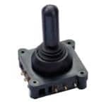
| 产品图片 |
|
| 产品型号 | 1V15F1100 |
| rohs | 无铅 / 符合限制有害物质指令(RoHS)规范要求 |
| 产品系列 | 1000 |
| 不同电压时的触头额定电流 | 6A @ 250VAC |
| 产品培训模块 | http://www.digikey.cn/PTM/IndividualPTM.page?site=cn&lang=zhs&ptm=25300http://www.digikey.cn/PTM/IndividualPTM.page?site=cn&lang=zhs&ptm=25711 |
| 产品目录页面 | |
| 作用力 | - |
| 其它名称 | 679-1405 |
| 开关功能 | 可配置 |
| 标准包装 | 1 |
| 特色产品 | http://www.digikey.com/cn/zh/ph/apem/joysticks.html |
| 端子类型 | 焊片 |
| 类型 | 操纵杆,面板安装 |
| 致动器类型 | 操纵杆 |
| 输出 | 机械开关 |





- 商务部:美国ITC正式对集成电路等产品启动337调查
- 曝三星4nm工艺存在良率问题 高通将骁龙8 Gen1或转产台积电
- 太阳诱电将投资9.5亿元在常州建新厂生产MLCC 预计2023年完工
- 英特尔发布欧洲新工厂建设计划 深化IDM 2.0 战略
- 台积电先进制程称霸业界 有大客户加持明年业绩稳了
- 达到5530亿美元!SIA预计今年全球半导体销售额将创下新高
- 英特尔拟将自动驾驶子公司Mobileye上市 估值或超500亿美元
- 三星加码芯片和SET,合并消费电子和移动部门,撤换高东真等 CEO
- 三星电子宣布重大人事变动 还合并消费电子和移动部门
- 海关总署:前11个月进口集成电路产品价值2.52万亿元 增长14.8%

.jpg)
PDF Datasheet 数据手册内容提取
1000 series Compact switch joysticks Distinctive features and specifications Compact size Robust construction Single or dual axis Single or double pole Gold contacts Bushing or screw mount V4 switches V3 switches Alternative handle selection including pushbutton handles MECHANICAL ELECTRICAL • Mechanical Life: >5 Million Operations • Number of Switches: 2, 4, or 8 • Lever Travel: 24º (12º from center) • Nominal Current: 6A, 10A, or 16A • Lever Material: Stainless Steel or Brass • Maximum Voltage: 250V AC • Mass/weight: 40g • Contacts #1 6A - V4: Gold • Body Material: Mineral Filled Nylon-6 • Contacts #2 16A - V3: Silver • Handle Material: See Handles Page • Contacts #3 10A - V4: Silver • Boot Material: Neoprene • Contacts #4 Right Angle: Silver • Mounting - Screw: 4 x M2.5 Stainless (Slotted) • Contacts #5 Faston Style - V4: Silver • Mounting - Bush: Single Point 22mm Diameter • Contacts #6 Faston Style - V3: Silver • Contacts #7: Silver ENVIRONMENTAL • Switch Contacts: Changeover • Contact Life: Load Dependent • Temperature Range: -20ºC to 50ºC • Pushbutton Cable: Blue (-4ºF to 122ºF)³ • Above Panel Seal (IP): To IP67¹ NOTES: – All values are nominal. 1. Excludes some handle options. 2. Exact specifications may be subject to configuration. Contact Technical Support for the performance of your specific configuration. 3. Temperature specification may be subject to the chosen switch option. Please refer to factory. Switches Poles Handle Boot 1 6A - V4* 1 Single Pole BL Round 1 Screw Mount 2 16A - V3 2 Double Pole* D Cylindrical 5 Bush Mount* 3 10A - V4* F Conical 4 Right Angle V4* Lever H Tall Conical Modifier 5 5A/250V AC - V4* J Pushbutton* Faston Style 1 Long* M Pushbutton* 00 None 6 5A/250V AC - V3 5 Standard V4* T Pushbutton* 34 + Limiter Fitted Faston Style with 6 For Pushbutton V4* V Bullet 39 Slot Limiter Fitted screw fixing 7 For Double Pole V4 or V3 AE Rocker* 7 10A/250V AC - V4* IP67 9 Double Pole and Pushbutton V4* AJ Stainless Steel Limiter And Mounting Bezel Set D 22mm Bush* 0 Not Supplied V 4 Point Screw * Unavailable with V3 construction 1 Standard Note: The company reserves the right to change specifications without notice. APEM www.apem.com
1000 series Compact switch joysticks Overview 14.00 (0.55) 45° 12.70 (0.50) Ø32.00 (1.26) 15.00 (0.59) 45.00 (1.77) 35.00 30.00 (1.38) (1.18) 20.00 (0.79) 3 BL D F H 15.50 10.00 8.50 (0.61) (0.39) (0.33) MATERIAL Phenolic Aluminum Nylon Stainless Steel FINISH Gloss Anodized Matt Natural STANDARD COLOR Black Black Black Stainless Steel OTHER COLORS Not Available Not Available Red Not Available NOTES: Supplied Loose 17.50 17.50 17.50 17.50 7.90 (0.69) (0.69) (0.69) (0.69) (0.35) 3.20 (0.13) 13.60 13.60 13.60 (0.54) (0.54) (0.54) 17.60 (0.78) 33.50 31.70 (1.32) 31.00 31.00 31.00 (1.24) 31.00 (1.22) (1.22) (1.22) (1.22) J M T V AE AJ MATERIAL ABS Aluminum Stainless Steel ABS Aluminum S t a i n l e s s S t e e l FINISH Matt Anodized Polished Gloss Anodized P oli s h e d STANDARD COLOR Black Black Stainless Black Black Stainless S t e e l OTHER COLORS Upon Request Not Available Not Available Upon Request Not Available Not Available NOTES: Uses APEM IS Switch Uses APEM IS Switch Uses APEM IS Switch Uses APEM TR Switch NOTES: 1. Dimensions are in mm/(inch). 2. Pushbutton (J, M, T) and rocker switches (AE) are for bushmount configurations only. Dimensions are shown below. 3. Handle is supplied loose because it is larger than panel cutout. The handle should be press fitted to the joystick, once the joystick is installed in the panel. 4. Unless otherwise specified, all joysticks are supplied with black switches in the handles. 17.50 (0.69) 17.50 13.60 (0.69) (0.54) 3.20 (0.13) 31.00 33.50 (1.22) (1.32) 54.50 57.00 (2.15) (2.24) 23.00 23.00 (0.91) (0.91) Note: The company reserves the right to change specifications without notice. www.apem.com APEM
1000 series Compact switch joysticks Overview V4 BUSH MOUNT 15.00 (0.59) 36.00 (1.42) 20.00 (0.79) 41.00 (1.61) 36.00 (1.42) 23.00 (0.91) 44.00 (1.73) V4 SCREW MOUNT 20.00 (0.79) 15.00 36.00 (0.59) (1.42) 41.00 (1.61) 36.00 (1.42) 23.00 44.00 (0.91) (1.73) V4 SCREW MOUNT DOUBLE POLE 36.00 (1.42) 40.00 (1.57) 36.00 (1.42) 27.50 (1.08) 44.00 (1.73) V3 SCREW MOUNT 43.00 53.50 45.50 (1.69) (2.11) (1.79) 24.50 45.50 (0.96) (1.79) 53.50 (2.11) NOTES: Dimensions are in mm/(inch). Note: The company reserves the right to change specifications without notice. APEM www.apem.com
1000 series Compact switch joysticks Overview MOUNTING CUTOUT DIMENSIONS AND INSTALLATION V4 SCREW MOUNT NOTE: The joystick is mounted from beneath the panel using the 4 x M2.5 machine screws, supplied with the joystick. Supplied as standard with the joystick is a round bezel which may be fitted (according to customer Ø20.00 preference) to finish the front face of the panel. 36.00 (0.79) (1.42) Fitting the bezel is optional, and is not necessary if the panel cut-out finishes the panel.If fitting the Ø2.80 x 4 bezel is selected then the panel cut out should be (0.11) toleranced such that the bezel is an interference fit. 36.00 Additionaly bonding the bezel is recommended. (1.42) V4 BUSH MOUNT 22.00 (0.87) NOTE: The joystick is mounted from beneath the panel. Supplied as standard with all bush mount joysticks, 9.20 is an adhesive PVC sealing gasket. This should be (0.36) fitted between the joystick and the panel, in applications where a good seal is needed. 20.00 (0.79) V3 SCREW MOUNT NOTE: The joystick is mounted from beneath the panel using the 4 x M2.5 machine screws, supplied with the joystick. Supplied as standard with the joystick 45.50 (1.79) is a round bezel which may be fitted (according to Ø20.00 customer preference) to finish the front face of the (0.79) panel. Fitting the bezel is optional, and is not necessary if the panel cut-out finishes the panel. If fitting the bezel is selected then the panel cut out should be toleranced such that the bezel is an 45.50 interference fit. Additionaly bonding the bezel is (1.79) Ø2.80 x 4 (0.11) recomended. LIMITERS AND BEZEL SET 20.00 (0.79) 45° 16.50 18.00 (0.65) (0.71) 22.00 4.00 24.50 (0.87) (0.16) (0.96) 2.55 (0.10) NOTE: 1. Dimensions are in mm/(inch). Note: The company reserves the right to change specifications without notice. www.apem.com APEM
1000 series Compact switch joysticks Overview SWITCHES Seven switch options are specified as standard. All are configured with changeover contacts, allowing the user flexibility of connection. Option 1 - V4 - 6A/240V AC should be specified where the joystick will be switching smaller current levels. These switches are supplied with gold flash terminals to ensure reliable switching at very low current levels. Option 2 - V3 - 16A/240V AC should be specified where the joystick will be switching up to 16A. Option 3 - V4 - 10A/240V AC should be specified where the joystick may be switching up to 10A. Option 4 - V4 - 5A/250V AC with right angle terminals, should be specified for PCB mounting or simpler termination. Option 5 - V5 - 5A/250V AC with 2.8mm Faston style terminals. Option 6 - V3 - 16A/250V AC with long terminals and screw fixing. Option 7 - V4 - 10A/250V AC sealed to IP67. Note: The construction of the joystick employing V3 switches is not available with as many configuration options. Life and reliability of the switches is heavily determined by the type of application and parameters such as load. Contact the factory for further advice about the expected switch performance under differing loads or DC supplies. MECHANICAL OPERATION All 1000 series are supplied with an open square gate. As a standard option the joystick may be supplied with an additional plastic limiter set, that allows the customer to retro-fit limiters to reduce the travel to single axis(-), cross (+) or diagonal (X) operation. For harsh environments metal limiters are also available. Joysticks are supplied as standard without a cable harness, allowing the user flexibility of connection. Alterna- tively the joystick may be factory configured with fitted limiters or cable harnesses, upon customer request. SEALING Two boot options are offered as standard to provide an above-panel seal. When specifying a bush mount joystick select boot option 5 which yields an IP65 seal. Alternatively boot option 1 should be selected for 4 point screw mount joysticks which yields an IP67 seal. As standard, a sealing gasket is supplied with all bush mount joysticks, to ensure a good seal between the joystick body and the panel. The sealing standards quoted are panel seals. It is assumed that the below panel area will be sealed. For applications where below panel seal can not be assured, switch option 7 should be selected. DOUBLE POLE OPERATION The construction of the joystick is designed such that both switches nominally trigger simultaneously. Such simultaneous triggering is subject to a ±2º tolerance (between switches) owing to the mechanical tolerances and hysterisis of each switch. MOUNTING The 1000 series is available in two mounting options, four point screw mount or bush mount. The V4 screw mount option is supplied with M2.5 x 20mm screws, whereas the larger construction of V3 screw mount joystick is supplied with M2.5 x 25mm screws. All screws supplied are slotted, pan head machine screws, although longer pan head screws, or countersunk heads are also available upon request. LEVERS Lever option 5 provides for a low profile above the panel (41mm/1.61inch), this option is very popular for those applications requiring a compact, stubby design. Lever option 1 is an additional 5mm/0.20inch taller. Lever option 6 should be specified for a push button handle, and lever option 7 is designed for V4 double-pole, or V3 constructions. Lever option 9 is for double-pole and pushbutton joysticks. Additional custom levers are available upon request. Note: The company reserves the right to change specifications without notice. APEM www.apem.com 1000_JOYST1603R2US
Mouser Electronics Authorized Distributor Click to View Pricing, Inventory, Delivery & Lifecycle Information: A pem: 1WP53 1V15F1100 1D15F1500 1D11P
 Datasheet下载

