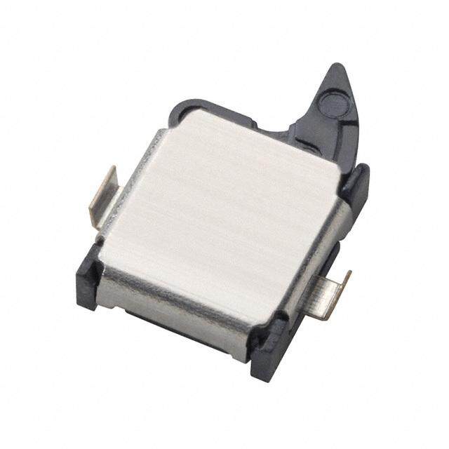
- 型号: 1SE1
- 制造商: Honeywell Solid State Electronics
- 库位|库存: xxxx|xxxx
- 要求:
| 数量阶梯 | 香港交货 | 国内含税 |
| +xxxx | $xxxx | ¥xxxx |
查看当月历史价格
查看今年历史价格
1SE1产品简介:
ICGOO电子元器件商城为您提供1SE1由Honeywell Solid State Electronics设计生产,在icgoo商城现货销售,并且可以通过原厂、代理商等渠道进行代购。 1SE1价格参考¥543.71-¥698.59。Honeywell Solid State Electronics1SE1封装/规格:快动,限位开关, Switch SPDT Chassis Mount。您可以下载1SE1参考资料、Datasheet数据手册功能说明书,资料中有1SE1 详细功能的应用电路图电压和使用方法及教程。
| 参数 | 数值 |
| 产品目录 | |
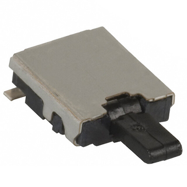
| 描述 | SWITCH SPDT 5A AT 250 VAC基本/快动开关 5A @ 250 VAC SPDT |
| 产品分类 | |
| 品牌 | Honeywell |
| 产品手册 | http://sensing.honeywell.com/index.cfm?ci_id=140301&la_id=1&pr_id=112249 |
| 产品图片 |
|
| rohs | 否无铅 / 符合限制有害物质指令(RoHS)规范要求 |
| 产品系列 | 基本/快动开关,Honeywell 1SE1* |
| mouser_ship_limit | 该产品可能需要其他文件才能进口到中国。 |
| 数据手册 | |
| 产品型号 | 1SE1 |
| 产品种类 | 基本/快动开关 |
| 其它名称 | 1SE1-ND |
| 商标 | Honeywell |
| 商标名 | Microswitch |
| 工作力 | 1.4 N |
| 开关功能 | ON - (OFF), OFF - (ON) |
| 执行器 | Plunger, Pin |
| 标准包装 | 1 |
| 电压额定值AC | 250 V |
| 电压额定值DC | 30 V |
| 电流额定值 | 5 A |
| 端接类型 | Wire Leads |
| 触点形式 | SPDT |





- 商务部:美国ITC正式对集成电路等产品启动337调查
- 曝三星4nm工艺存在良率问题 高通将骁龙8 Gen1或转产台积电
- 太阳诱电将投资9.5亿元在常州建新厂生产MLCC 预计2023年完工
- 英特尔发布欧洲新工厂建设计划 深化IDM 2.0 战略
- 台积电先进制程称霸业界 有大客户加持明年业绩稳了
- 达到5530亿美元!SIA预计今年全球半导体销售额将创下新高
- 英特尔拟将自动驾驶子公司Mobileye上市 估值或超500亿美元
- 三星加码芯片和SET,合并消费电子和移动部门,撤换高东真等 CEO
- 三星电子宣布重大人事变动 还合并消费电子和移动部门
- 海关总署:前11个月进口集成电路产品价值2.52万亿元 增长14.8%



PDF Datasheet 数据手册内容提取
MICRO SWITCH™ Miniature Sealed Basic Switches SE and XE Series Datasheet
MICRO SWITCH™ SE and XE Series Miniature Sealed Basic Switches Honeywell SE and XE miniature sealed basic switches are designed for precise and reliable position indication of critical applications on aircraft and military systems. The applications range from military and commercial aircraft and helicopters to military land vehicles (track and wheeled vehicles). These switches are also suitable for other commer- cial and industrial applications where a degree of environmental sealing is required. The environmentally sealed SE Series is designed for demanding applications where water and/or particulate contam- inant is present along with the potential for a wide range of temperatures. The SE Series incorporates the Honeywell time-proven MICRO SWITCH™ SM Series electromechanical switches in the SE housing. The environmentally sealed miniature XE Series is similar to the SE Series except smaller in package size, utilizing the Honeywell MICRO SWITCH™ SX subminiature electromechanical switch. In addition, select Honeywell XE switches are MIL-PRF-8805 qualified satisfying the requirements where a military qualified or compliant switch is required. To add to the versatility of the SE and XE family of products, CSA and UL certified products are available where the application is not aerospace or military related. What makes our switches better? SE Series is certified by UL and CSA. XE Series holds approval from UL and within the family qualified to MIL-PRF-8805 Built with high quality MICRO SWITCH™ switching mechanism: SE Series features MICRO SWITCH™ SM switches and XE Series is built with MICRO SWITCH™ SX switches Available with pin plungers or auxiliary levers to meet equipment requirements Designed for control of circuits ranging from logic level to power duty Big performance in a little package. HIGH PERFORMANCE • DURABILITY COMPACT • CUSTOMIZATION/CONFIGURABLE 2 sensing.honeywell.com
FFeeaattuurreess MIL-QUALIFIED AND AGENCY CERTIFIED Military qualified listings offered in the MICRO SWITCH™ XE product family aanndd BBeenneefifittss are for onboard or support equipment as specified. UL and CSA certified products are available for use where the application is not aerospace or military related. COMPACT AND SEALED Miniature overall package size requires less space on the equipment. SE and XE Series switches are environmentally sealed in a small package for stringent indoor or outdoor applications where liquid and/or particulate contaminates are present. Tiny, tough, and high-temp rated WELL SUITED FOR HIGH TEMPERATURES SE/XE switches boast temperature ratings from -53 °C to 105 °C [-65 °F to 221 °F] for design flexibility, with high temperature options to 149 °C [300 °F]. LOW VOLTAGE AND POWER DUTY CAPABILITY SE/XE product are available with silver contacts for control of power duty circuits or gold contacts for control of logic level circuits. LEVERS FURTHER EXPAND FUNCTIONALITY Auxiliary actuators expand the capability of the products for additional applications. RANGE OF TERMINATION OPTIONS Electrical connectivity options include solder post, preleaded with MIL-rated leadwire, or custom connectivity to decrease installation time. sensing.honeywell.com 3
Potential Applications MILITARY AIRCRAFT AND HELICOPTERS • Monitor doors or panels whether open/closed or locked/unlocked • Mechanical position of actuators • Valve position open or closed in conjunction with the hydraulics, fuel, and other systems • Missile, bomb, and ordnance systems COMMERCIAL AIRCRAFT AND HELICOPTERS • Monitor doors or panels whether open/closed or locked/unlocked • Mechanical position of actuators • Valve position open or closed in conjunction with the hydraulics, fuel, and other systems AVIATION GROUND SUPPORT EQUIPMENT • Monitoring doors or panels • Valve position whether open or closed MILITARY LAND VEHICLES (TRACK AND WHEELED VEHICLES) • Monitor position of doors, guards • Monitor position of valves and solenoids 4 sensing.honeywell.com
MICRO SWITCH™ Miniature Sealed Basic Switches Table 1. Specifications Characteristic SE Series XE Series Description environmentally sealed switch environmentally sealed miniature switch Housing material Anodized aluminum Anodized aluminum Mechanical endurance please contact info.sc@honeywell.com for details 25,000 Electrical endurance please contact info.sc@honeywell.com for details 25,000 Circuitry SPST (NC), SPST (NO), SPDT SPST (NC), SPST (NO), SPDT epoxy sealed leadwire, (0,52 mm² [20 awg]) or epoxy sealed leadwire, (0,52 mm² [20 awg]) or Electrical termination epoxy sealed solder pins epoxy sealed solder pins Electrical rating 5 A @ 30 Vdc; 5 A @ 250 Vac, 60 Hz 7 A @ 28 Vdc; 7 A @ 250 Vac, 60 Hz Sealing Symbol 3 “watertight” per MIL-PRF-8805 Symbol 3 “watertight” per MIL-PRF-8805 -53 °C to 105 °C [-65 °F to 221 °F] (standard) -53 °C to 105 °C [-65°F to 221 °F] (standard) Temperature range -26 °C to 85 °C [-15 °F to 185 °F] (5SE Series) -26 °C to 85 °C [-15 °F to 185 °F] (5XE Series) Temperature range (optional) please contact info.sc@honeywell.com for details -53 °C to 149 °C [-65°F to 300 °F] (14XE Series) Vibration Grade 2 (15 G) per MIL-PRF-8805 Grade 2 (15 G) per MIL-PRF-8805 Approvals UL, CSA UL, MIL-PRF-8805 Actuators Top pin plunger, optional auxiliary actuators available Top pin plunger, optional auxiliary actuators available Table 2. Electrical Ratings Rating code SE/XE Series Sea level @ 28 Vdc; 5 A res. and 3 A ind. A 50,000 feet @ 28 Vdc; 5 A res. and 2.5 A ind. General purpose; 5 A res. and 5 A ind. at 125 or 250 Vac, 60 Hz B UL and CSA rating; 5 A at 125 or 250 Vac, 60 Hz Sea level @ 28 Vdc; 7 A res. and 4 A ind. C 50,000 feet @ 28 Vdc; 7 A res. and 2.5 A ind. General purpose; 7 A res. and 4 A ind. at 115 Vac, 400 Hz D UL rating; 7 A at 125 or 250 Vac, 60 Hz Sea level @ 28 Vdc; 7 A res. and 4 A ind. E 50,000 feet @ 28 Vdc; 7 A res and 2.5 A ind. F Logic level @ 28 Vdc; 1 amp res. and 0.50 A ind. sensing.honeywell.com 5
SE and XE Series ELECTROMECHANICAL SWITCHES Operating Position (O.P.) – Position of Overtravel (O.T.) – Plunger or actuator switch plunger or actuator at which point travel safely available beyond operating Definitions below explain the meaning of contacts snap from normal to operated position. operating characteristics. Characteristics position. Note that in the case of flexible shown in tables were chosen as most Pretravel (P.T.) – Distance or angle trav- or adjustable actuators, the operating significant. They are taken at normal room eled in moving plunger or actuator from position is measured from the end of the temperature and humidity. These may vary free position to operating position. lever or its maximum length. Location of as temperature and humidity conditions Release Force (R.F.) – Amount of force operating position measurement shown on differ. Sketches show how characteristics still applied to switch plunger or actuator mounting dimension drawings. are measured for in-line plunger actuation. at moment contacts snap from operated Operating Force (O.F.) – Amount of force Linear dimensions for in-line actuation are position to unoperated position. applied to switch plunger or actuator to from top of plunger to a reference line, Total Travel (T.T.) – Distance from actuator cause contact ‘‘snap-over.’’ Note in the usually the center of the mounting holes. free position to overtravel limit position. case of adjustable actuators, the force is Differential Travel (D.T.) – Plunger or measured from the maximum length posi- actuator travel from point where contacts tion of the lever. ‘‘snap-over’’ to point where they ‘‘snap- back.’’ Free Position (F.P.) – Position of switch plunger or actuator when no external force is applied (other than gravity). Full Overtravel Force – Force required to attain full overtravel of actuator. 6 sensing.honeywell.com
MICRO SWITCH™ Miniature Sealed Basic Switches O.F. • Operating force R.F. • Release force P.T. • Pretravel MICRO SWITCH™ SE PRODUCT SPECIFICATIONS AND LISTINGS O.T. • Overtravel D.T. • Differential travel Contact your Honeywell rep or distributor for additional listings O.P. • Operating position Elect. D.T. O.P. Termin- R.F. P.T. max. O.T. min. Catalog Rating O.F. max. nom. Contacts ation min. mm mm Comment Listing Spec. g [oz] mm mm mm [in] g [oz] [inches] [inches] (page 5) [inches] [inches] Wire 142 to 482 1,27 0,08 0,1 10,8 General 1SE1 A SPDT leads (3) 113 [4] [5 to 17] [0.050] [0.003] [0.004] [0.425] purpose 305 [12] Wire SPST, 142 to 482 1,27 0,08 0,1 10,8 Single circuit 1SE2 A leads (2) 113 [4] NC [5 to 17] [0.050] [0.003] [0.004] [0.425] only 305 [12] Wire SPST, 142 to 482 1,27 0,08 0,1 10,8 Single circuit 1SE3 A leads (2) 113 [4] NO [5 to 17] [0.050] [0.003] [0.004] [0.425] only 305 [12] Wire Gold 142 to 482 1,27 0,08 0,1 10,8 1SE401 F SPDT leads (3) 113 [4] bifurcated [5 to 17] [0.050] [0.003] [0.004] [0.425] 305 [12] contacts Wire 142 to 482 1,27 0,08 0,1 10,8 4SE1 B SPDT leads (3) 113 [4] UL, CSA (see Figure 1) 305 [12] [5 to 17] [0.050] [0.003] [0.004] [0.425] Wire Oil resistant 142 to 482 1,27 0,08 0,1 10,8 5SE1 A SPDT leads (3) 113 [4] fluorosilicone [5 to 17] [0.050] [0.003] [0.004] [0.425] 305 [12] seal Wire 113 to 227 1,27 0,08 0,1 10,8 7SE1 A SPDT leads (3) 57 [2] Lower force [4 to 8] [0.050] [0.003] [0.004] [0.425] 305 [12] Solder 142 to 482 1,27 0,08 0,1 10,8 Solder 1SE1-T A SPDT 113 [4] pins [5 to 17] [0.050] [0.003] [0.004] [0.425] terminals Solder 142 to 539 1,27 0,08 0,1 10,8 12SE4-T A SPDT 113 [4] Higher force pins [5 to 19] [0.050] [0.003] [0.004] [0.425] (see Figure 2) sensing.honeywell.com 7
SE and XE Series O.F. • Operating force R.F. • Release force P.T. • Pretravel MICRO SWITCH™ XE PRODUCT SPECIFICATIONS AND LISTINGS O.T. • Overtravel D.T. • Differential travel Contact your Honeywell rep or distributor for additional listings O.P. • Operating position Elect. Termin- R.F. P.T. O.T. D.T. O.P. Catalog Rating O.F. Contacts ation min. max. min. max. nom. Comment Listing Spec. g [oz] mm [in] g [oz] mm [in] mm [in] mm [in] mm [in] (page 5) Wire leads MIL-PRF 1XE1* 142 to 482 1,27 0,1 0,13 10,8 C SPDT (3) 305 113 [4] 8805 [MS27994-1] [5 to 17] [0.050] [0.004] [0.005] [0.425] [12] applications Wire leads MIL-PRF 1XE201* 142 to 482 1,27 0,1 0,13 10,8 C SPDT (3) 305 113 [4] 8805 [MS27994-4] [5 to 17] [0.050] [0.004] [0.005] [0.425] [12] applications Wire leads Normally 142 to 482 1,27 0,1 0,13 10,8 1XE2-3 C SPNC (2) 914 113 [4] closed [5 to 17] [0.050] [0.004] [0.005] [0.425] [36] circuit Wire leads 142 to 482 1,27 0,1 0,13 10,8 Normally 1XE3 C SPNO (3) 305 113 [4] [5 to 17] [0.050] [0.004] [0.005] [0.425] open circuit [12] Wire leads Gold 1XE301* 142 to 482 1,27 0,1 0,13 10,8 F SPDT (3) 305 113 [4] bifurcated [MS27994-5] [5 to 17] [0.050] [0.004] [0.005] [0.425] [12] contacts Wire leads (see Figure 3) 142 to 482 1,27 0,1 0,13 10,8 4XE1 D SPDT (3) 305 113 [4] UL [5 to 17] [0.050] [0.004] [0.005] [0.425] [12] Wire leads Oil resistent 142 to 482 1,27 0,1 0,13 10,8 5XE1 C SPDT (3) 305 113 [4] fluorosilicone [5 to 17] [0.050] [0.004] [0.005] [0.425] [12] seal Wire leads High temp. 255 [9] 0,76 0,1 0,13 10,9 14XE1 E SPDT (3) 305 57 [2] 149 °C max. [0.030] [0.004] [0.005] [0.430] [12] [300 °F] Gold Solder 142 to 482 1,27 0,1 0,13 10,8 1XE401-T F SPDT 85 [3] bifurcated pins [5 to 17] [0.050] [0.004] [0.005] [0.425] contacts High temp. Solder 255 [9] 0,76 0,1 0,13 10,9 14XE1-T E SPDT 57 [2] 149 °C pins max. [0.030] [0.004] [0.005] [0.430] [300 °F] 14XE1-T* Solder 142 to 482 1,27 0,1 0,13 10,8 Mil-PRF (see Figure 4) C SPDT 113 [4] [MS27994-3] pins [5 to 17] [0.050] [0.004] [0.005] [0.425] 8805 * Reference MIL-PRF-8805/32 8 sensing.honeywell.com
MICRO SWITCH™ Miniature Sealed Basic Switches MICRO SWITCH™ JE SERIES AUXILIARY ACTUATORS FOR THE MICRO SWITCH™ SE SERIES SWITCHES (specifications when assembled to 1SE1) Description Actuator Operting Release Pretravel Overtravel Differential Operating Free Length Force Force min. max. min. Travel max. Point Position max. nom. nom. Straight leaf 16,8 mm 340 g 57 g 3,81 mm 0,38 mm 0,64 mm 11,2 mm 15 mm (mounting [0.66 in] [12 oz] [2 oz] [0.150 in] [0.015 in] [0.025 in] [0.44 in] [0.59 in] 1 hardware E- included) J (see Figure 5) Roller leaf, roller 16,8 mm 340 g 57 g 3,81 mm 0,38 mm 0,64 mm 16,3 mm 20,1 mm rotated 90° to [0.66 in] [12 oz] [2 oz] [0.150 in] [0.015 in] [0.025 in] [0.64 in] [0.79 in] 4 switch axis E- (mounting J hardware included) (see Figure 6) Roller leaf 15,2 mm 340 g 57 g 3,81 mm 0,38 mm 0,64 mm 16,3 mm 20,1 mm (mounting [0.60 in] [12 oz] [2 oz] [0.150 in] [0.015 in] [0.025 in] [0.64 in] [0.79 in] 5 hardware E- included) J (see Figure 7) Roller leaf 15,2 mm 340 g 57 g 3,81 mm 0,38 mm 0,64 mm 16,3 mm 20,1 mm [reversed] [0.60 in] [12 oz] [2 oz] [0.150 in] [0.015 in] [0.025 in] [0.64 in] [0.79 in] 7 (mounting 1 E- hardware J included) (see Figure 8) Roller lever 13,7 mm 170 g 28 g 2,54 mm 0,25 mm 0,41 mm 16,3 mm 18,8 mm [0.540 in] [6 oz] [1 oz] [0.100 in] [0.01 in] [0.016 in] [0.64 in] [0.74 in] 1 2 E- J (see Figure 9) Tandem roller 17,8 mm 482 g 113 g 2,54 mm 0,15 mm 0,3 mm 16,8 mm 19,3 mm lever [0.700 in] [17 oz] [4 oz] [0.100 in] [0.006 in] [0.012 in] [0.66 in] [0.76 in] 2 2 E- J (see Figure 10) ** Travel characteristics on tandem actuators vary with actual basic switch characteristics MICRO SWITCH™ JM SERIES AUXILIARY ACTUATORS FOR THE MICRO SWITCH™ XE SERIES SWITCHES (specifications when assembled to 1XE1) Description Actuator Operating Release Pretravel Overtravel Differential Operating Free Length Force Force max. min. Travel Point Position max. min. max. nom. nom. Straight leaf 11,4 mm 595 g 85 g 3,18 mm 0,23 mm 0,3 mm 10,8 mm 14 mm (mounting [0.45 in] [21 oz] [3 oz] [0.125 in] [0.009 in] [0.012 in] [0.425 in] [0.55 in] 1 hardware M- included) J (see Figure 11) Roller leaf 9,5 mm 595 g 85 g 3,18 mm 0,23 mm 0,3 mm 15,9 mm 19,1 mm (mounting [0.375 in] [21 oz] [3 oz] [0.125 in] [0.009 in] [0.012 in] [0.625 in] [0.75 in] 5 hardware M- included) J (see Figure 12) ** Travel characteristics on tandem actuators vary with actual basic switch characteristics sensing.honeywell.com 9
SE and XE Series PRODUCT AND ACTUATOR DIMENSIONS Figure 1. MICRO SWITCH™ SE Dimensions, Wire Lead Figure 2. MICRO SWITCH™ SE Dimensions, Solder Terminal 22,25 [0.876] 22,25 [0.876] 9,53 [0.375] 9,53 [0.375] 6,35 [0.25] 6,35 [0.25] Corrosion-resistant Corrosion-resistant treated metal treated metal enclosure 8,79 [0.346] enclosure 8,79 [0.346] 7,5 [0.296] 7,5 [0.296] Corrosion-resistant Corrosion-resistant steel plunger Elastomer Ø 1,98 [Ø 0.078] steel plunger Elastomer Ø 1,98 [Ø 0.078] 1p,r2e7tr a[0ve.0l5] max. Øpl u2n,3g e[Ør s 0e.a0l88] R 1,78 [0.07] spherical 1p,r2e7tr a[0ve.0l5] max. Øpl u2n,3g e[Ør s 0e.a0l88] R 1,78 [0.07] spherical 10,8 [0.425] 10,8 [0.425] oppoesriatitoinng 9,5 [0.38] 8,38 [0.33] oppoesriatitoinng 9,5 [0.38] 8,38 [0.33] 6,9 [0.27] 6,9 [0.27] 2,3 [0.088] 850,9 [33.5] min. 2,3 [0.088] Ø 2,5 [Ø 0.098] No. 20 wire lead per Ø 2,5 [Ø 0.098] MIL-W-22759/11 3,56 [0.14] 12,29 [0.484] embedded in epoxy 22,35 [0.88] casting resin Figure 3. MICRO SWITCH™ XE Dimensions, Wire Lead Figure 4. MICRO SWITCH™ XE Dimensions, Solder Terminal 15,65 [0.616] 15,65 [0.616] 8,03 [0.316] 8,03 [0.316] Corrosion-resistant treated metal enclosure Corrosion-resistant treated metal enclosure Corrosion-resistant steel plunger Corrosion-resistant steel plunger Ø 1,52 [Ø 0.06] 4,78 [0.188] Ø 1,52 [Ø 0.06] 1p,r2e7tr a[0ve.0l5] max. Eplluanstgoemr esreal R 1,78 [0.07] spherical 1,27 [0.05] max. 4,78 [0.188] pretravel Elastomer R 1,78 [0.07] plunger seal spherical 10,8 [0.425] oppoesriatitoinng 8,38 [0.33] 10,8 [0.425] operating 8,38 [0.33] position 6,9 [0.27] Ø 2,31[Ø 0.091] max. mounting hole Elongated 304,8 [12.0] min. 6,9 [0.27] Ø 2,31[Ø 0.091] max. mounting mounting hole hole Elongated mounting hole No. 22 wire lead per M22759/11 4,78 [0.188] embedded in epoxy casting resin 4,78 [0.188] 5,44 [0.214] 5,44 [0.214] 10 sensing.honeywell.com
MICRO SWITCH™ Miniature Sealed Basic Switches Figure 5. JE-1 Dimensions Figure 6. JE-4 Dimensions Figure 7. JE-5 Dimensions Ø 4,8 [Ø 0.19] x 3,0 [0.12] W oil bronze roller 4,8 [0.19] 4,8 [0.19] 4,3 [0.17] 4,8 [0.19] 4,3 [0.17] 4,3 [0.17] 0,8 [0.03] Ø 4,8 [Ø 0.19] 0,8 [0.03] x 3,0 [0.12] W 16,8 [0.66] 16,8 [0.66] oil bronze roller 14,2 [0.56] 11,2 [0.44] operate 16,3 20,1 16,3 point [0.64] [0.79] [0.64] operating 12,7 12,7 position [0.50] [0.50] 2,3 [0.088] 2,3 [0.088] 6,4 [0.25] 6,4 [0.25] 6,4 [0.25] 9,5 [0.38] 9,5 [0.38] 9,5 [0.38] 23,9 [0.94] 23,9 [0.94] 23,9 [0.94] Figure 8. JE-17 Dimensions Figure 9. JE-21 Dimensions Figure 10. JE-22 Dimensions Ø 4,8 [Ø 0.19] Corrosion-resistant 3,6 [0.14] x 3,0 [0.12] W steel actuator and Ø 4,8 [Ø 0.19] oil bronze roller bracket (Type 302) x 3,0 [0.12] W 19,3 13,7 oil bronze roller 4,8 [0.19] [0.76] [0.64] 4,3 [0.17] 4,3 [0.17] 0,8 [0.03] 0,8 [0.03] Ø 4,8 [Ø 0.19] 14,2 [0.56] x 3,0 [0.12] W oil bronze roller 17,8 [0.70] 16,3 [0.64] 16,3 19,3 operating 18,8 [0.64] 16,3 [0.76] position [102.5,70] [0.74] [105.6,20] [0.64] 11,4 16.8 [0.45] [0.66] 2,3 [0.088] 2,3 [0.088] 6,4 [0.25] 9,5 [0.38] 6,4 [0.25] 6,4 [0.25] 23,9 [0.94] 9,5 [0.38] 9,5 [0.38] 23,9 [0.94] Figure 11. JM-1 Dimensions Figure 12. JM-5 Dimensions 4,1 [0.16] 4,1 [0.16] 5,8 [0.23] 5,8 [0.23] 9,7 [0.38] 11,4 [0.45] 2,3 [0.09] 2,3 [0.09] 4,78 [0.188] 5,44 [0.214] 4,78 [0.188] 5,44 [0.214] 17,0 [0.67] 17,0 [0.67] sensing.honeywell.com 11
SE and XE Series This Honeywell datasheet supports the following MICRO SWITCH™ SE/XE Series Basic Switch Listings 12SE2 1SE3-12 1XE313 5SE223-6 12SE3-3 1SE3-2 1XE314 5SE3-3 12SE42 1SE3-3 1XE315 5SE3-6 12SE4-2 1SE3-3N26 1XE316 5SE3-N43 12SE4-T 1SE36 1XE3-4 5SE401-T 12SE5-T 1SE3-6 1XE401-6 5SE-N2 12SE6 1SE3-N26 1XE401-T 5XE1 12SE7 1SE3-T 1XE41 5XE1-6 14XE1 1SE401 1XE70 5XE17 14XE1-12 1SE401-3 1XE79-3 5XE17-2 14XE1-6 1SE401-6 1XE8 5XE18 14XE17 1SE402-3 1XE83 5XE1-T 14XE17-T 1SE402-6 1XE92 5XE401-1 14XE1-T 1SE403 1XE97 5XE401-T 14XE24 1SE4-2 1XE99-T 5XE75 14XE4 1SE61-T 2SE156-3 6SE1 14XE65 1SE65 2SE157-3 6SE173 14XE66 1SE65-N64 2SE321 6SE175-3 1SE1 1SE65-N65 2SE322 6SE315 1SE105 1SE65-N82 2SE323 6SE801 1SE112 1SE7 2SE4 6SE803 1SE1-12 1SE7-3 2SE6 6XE21-4 1SE113-3 1SE-N21 2SE62 6XE27-1 1SE114-8 1XE1 2SE89 6XE60-4 1SE118-8 1XE122 2XE59 7SE1 1SE119 1XE1-3 2XE68 7SE19 1SE1-2 1XE1-6 39SE10 7SE1-T 1SE120 1XE17 39SE11 7SE9-T 1SE1-3 1XE18 39SE21 7XE1 1SE1-3N26 1XE1-GN6 39SE22-R 91SE1 1SE144 1XE1-T 39SE7 91SE1-12 1SE144-6 1XE201 39SE8 91SE1-3 1SE146-3 1XE202 39SE9 91SE13-3 1SE1-6 1XE203 39XE400-1 91SE1-3N55 1SE1-6N26 1XE204 39XE96 91SE1-3N62 1SE178 1XE205 4SE1 91SE1-3N69 1SE193 1XE206 4SE1-3 91SE1-3N85 1SE197 1XE207 4SE1-6 91SE1-4 1SE198 1XE21 4SE171 91SE14-1GN70 1SE1-H58 1XE2-1 4XE1 91SE141GN77 1SE1-N79 1XE214 4XE1-4 91SE14-1GN77 1SE1-T 1XE217 5SE1 91SE14-1N71 1SE2 1XE22 5SE1-12 91SE14-1N78 1SE201 1XE2-2 5SE1-3 91SE1-6 1SE202 1XE2-3 5SE1-6 91SE1N72 1SE209 1XE24-2 5SE166-12 91SE1-TG 1SE211 1XE25-2 5SE1-6N26 91SE2 1SE216-6 1XE2-6 5SE175-12 91SE2-3 1SE227 1XE26-2 5SE183-2 91SE2-6 1SE2-3 1XE27-2 5SE1-N27 91SE3 1SE25-10 1XE3 5SE1-T 91SE3-3 1SE26 1XE301 5SE2-1 91SE3-3N52 1SE2-6 1XE304 5SE218 91SE3-GN67 1SE2-T 1XE306 5SE2181-3 91SE3-N52 1SE3 1XE311 5SE218-3 91SE3-N84 12 sensing.honeywell.com
MICRO SWITCH™ Miniature Sealed Basic Switches ADDITIONAL INFORMATION WARNING The following associated literature is available on the Honeywell PERSONAL INJURY web site at sensing.honeywell.com: DO NOT USE these products as safety or emergency stop • Product installation instructions devices or in any other application where failure of the • Product range guide product could result in personal injury. • Aerospace and defense range guide Failure to comply with these instructions could result in death or serious injury. WARNING MISUSE OF DOCUMENTATION • The information presented in this product sheet is for reference only. Do not use this document as a product installation guide. • Complete installation, operation, and maintenance information is provided in the instructions supplied with each product. Failure to comply with these instructions could result in death or serious injury. WARRANTY/REMEDY Honeywell warrants goods of its manufacture as being free of defective materials and faulty workmanship. Honeywell’s standard product warranty applies unless agreed to otherwise by Honeywell in writing; please refer to your order acknowledgement or consult your local sales office for specific warranty details. If warranted goods are returned to Honeywell during the period of coverage, Honeywell will repair or replace, at its option, without charge those items it finds defective. The foregoing is buyer’s sole remedy and is in lieu of all other warranties, expressed or implied, including those of merchantability and fitness for a particu- lar purpose. In no event shall Honeywell be liable for conse- quential, special, or indirect damages. While we provide application assistance personally, through our literature and the Honeywell website, it is up to the customer to determine the suitability of the product in the application. Specifications may change without notice. The information we supply is believed to be accurate and reliable as of this printing. However, we assume no responsibility for its use. sensing.honeywell.com 13
Find out more Honeywell serves its customers through a worldwide network of sales offices, representatives and distributors. For application assistance, current specifications, pricing or name of the nearest Authorized Distributor, contact your local sales office. To learn more about Honeywell’s sensing and control products, call +1-815-235-6847 or 1-800-537-6945, visit sensing.honeywell.com, or e-mail inquiries to info.sc@honeywell.com Sensing and Control Honeywell 1985 Douglas Drive North Golden Valley, MN 55422 003122-1-EN IL50 GLO February 2015 honeywell.com Copyright © 2015 Honeywell International Inc. All rights reserved.

 Datasheet下载


