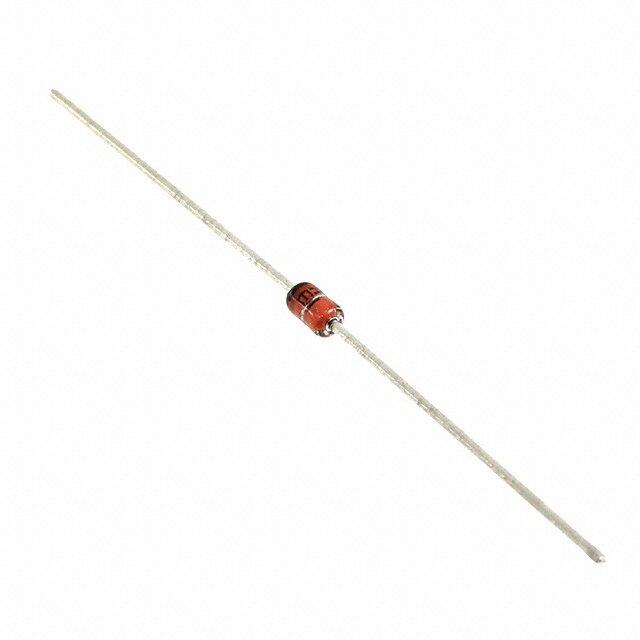
ICGOO在线商城 > 分立半导体产品 > 二极管 - 齐纳 - 单 > 1N5252B (DO-35)
- 型号: 1N5252B (DO-35)
- 制造商: American Microsemiconductor, Inc.
- 库位|库存: xxxx|xxxx
- 要求:
| 数量阶梯 | 香港交货 | 国内含税 |
| +xxxx | $xxxx | ¥xxxx |
查看当月历史价格
查看今年历史价格
1N5252B (DO-35)产品简介:
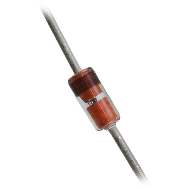
ICGOO电子元器件商城为您提供1N5252B (DO-35)由American Microsemiconductor, Inc.设计生产,在icgoo商城现货销售,并且可以通过原厂、代理商等渠道进行代购。 1N5252B (DO-35)价格参考¥6.08-¥6.08。American Microsemiconductor, Inc.1N5252B (DO-35)封装/规格:二极管 - 齐纳 - 单, Zener Diode 24V 500mW ±5% Through Hole DO-35。您可以下载1N5252B (DO-35)参考资料、Datasheet数据手册功能说明书,资料中有1N5252B (DO-35) 详细功能的应用电路图电压和使用方法及教程。
1N5252B是Microsemi Corporation生产的一款齐纳二极管,属于“二极管 - 齐纳 - 单”类别,采用DO-35封装。该型号的齐纳二极管具有稳定的反向击穿电压特性,通常用于电压调节、稳压、过压保护和信号电平控制等应用场景。以下是其主要应用场景:

1. 电压稳压:
   1N5252B可用于简单的直流电源电路中,提供稳定的输出电压。通过与电阻串联,它可以将输入电压稳定在特定的齐纳电压值(对于1N5252B,齐纳电压为10V)。

2. 过压保护:
   在敏感电子设备中,1N5252B可以用来防止电压过高对后续电路造成损害。当输入电压超过齐纳电压时,二极管导通并将电压钳位到安全范围。

3. 信号电平控制:
   在模拟电路中,1N5252B可以用作信号电平限制器。例如,在音频或射频电路中,它可以防止信号幅度超过设定的阈值。

4. 参考电压源:
   由于其稳定的齐纳电压特性,1N5252B可以用作简单的参考电压源,为其他电路模块提供基准电压。

5. 浪涌吸收:
   在电源或信号线中,1N5252B可以吸收瞬态电压浪涌,保护下游电路免受尖峰电压的影响。

6. 温度补偿电路:
   结合其他温度敏感元件,1N5252B可用于构建温度补偿电路,以减少因温度变化引起的电压波动。

总之,1N5252B适用于低功率、低成本的电路设计,尤其适合需要简单稳压或保护功能的应用场景。需要注意的是,其功率较小(最大功耗约为500mW),因此不适合高功率场合。
| 参数 | 数值 |
| 产品目录 | |
| 描述 | DIODE ZENER 24V 500MW DO35 |
| 产品分类 | 单二极管/齐纳 |
| 品牌 | Microsemi Commercial Components Group |
| 数据手册 | |
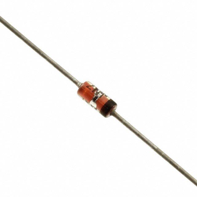
| 产品图片 |
|
| 产品型号 | 1N5252B (DO-35) |
| rohs | 含铅 / 不符合限制有害物质指令(RoHS)规范要求 |
| 产品系列 | - |
| 不同If时的电压-正向(Vf) | 1.5V @ 200mA |
| 不同 Vr时的电流-反向漏电流 | 100nA @ 18V |
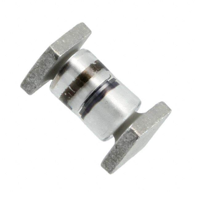
| 产品目录绘图 |
|
| 供应商器件封装 | DO-35 |
| 其它名称 | 1N5252B (DO-35)CT |
| 功率-最大值 | 500mW |
| 包装 | 剪切带 (CT) |
| 安装类型 | 通孔 |
| 容差 | ±5% |
| 封装/外壳 | DO-204AH,DO-35,轴向 |
| 工作温度 | -65°C ~ 175°C |
| 标准包装 | 1 |
| 电压-齐纳(标称值)(Vz) | 24V |
| 阻抗(最大值)(Zzt) | 33 欧姆 |



- 商务部:美国ITC正式对集成电路等产品启动337调查
- 曝三星4nm工艺存在良率问题 高通将骁龙8 Gen1或转产台积电
- 太阳诱电将投资9.5亿元在常州建新厂生产MLCC 预计2023年完工
- 英特尔发布欧洲新工厂建设计划 深化IDM 2.0 战略
- 台积电先进制程称霸业界 有大客户加持明年业绩稳了
- 达到5530亿美元!SIA预计今年全球半导体销售额将创下新高
- 英特尔拟将自动驾驶子公司Mobileye上市 估值或超500亿美元
- 三星加码芯片和SET,合并消费电子和移动部门,撤换高东真等 CEO
- 三星电子宣布重大人事变动 还合并消费电子和移动部门
- 海关总署:前11个月进口集成电路产品价值2.52万亿元 增长14.8%

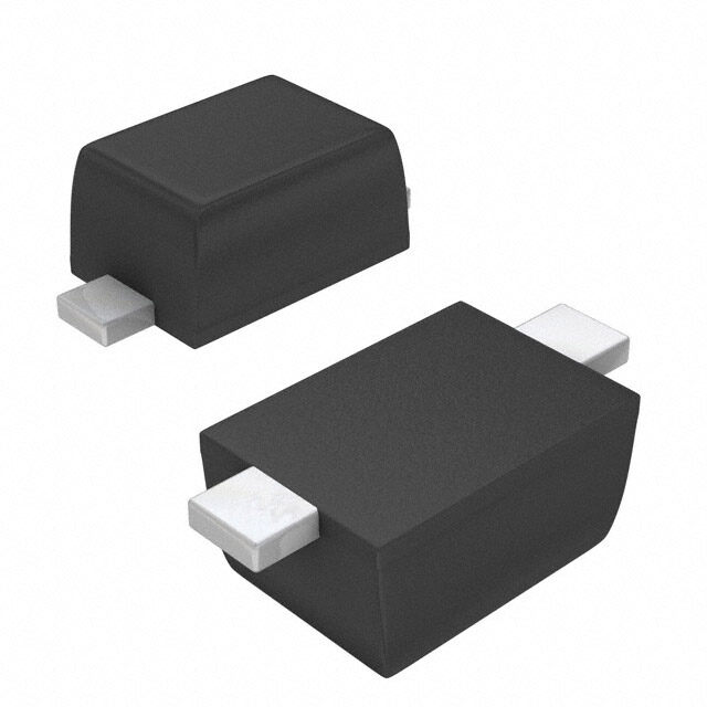
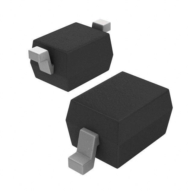
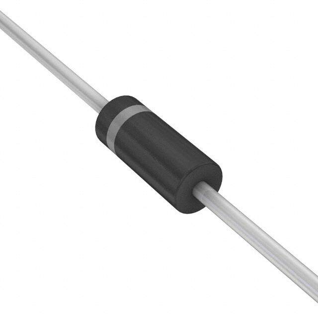
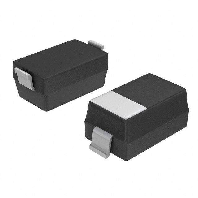
PDF Datasheet 数据手册内容提取
1N5221 thru 1N5281B, e3 DO-35 500 mW GLASS AXIAL-LEAD ZENER DIODES SCOTTSDALE DIVISION DESCRIPTION APPEARANCE W The popular 1N5221 thru 1N5281B series of 0.5 watt Zener Voltage Regulators DO-35 W provides a selection from 2.4 to 200 volts in standard 5% or 10% tolerances as W (DO-204AH) well as tighter tolerances identified by different suffix letters on the part number. . M These glass axial-leaded DO-35 Zeners are also available in various military ic screening levels by adding a prefix identifier as described in the Features r o section. Microsemi also offers numerous other Zener products to meet higher s e and lower power applications. m IMPORTANT: For the most current data, consult MICROSEMI’s website: http://www.microsemi.com i . C FEATURES APPLICATIONS / BENEFITS O • JEDEC registered 1N5221 to 1N5281B • Regulates voltage over a broad operating current M • Internal bonds optionally available with “-1” suffix and temperature range • Options for screening in accordance with MIL-PRF- • Extensive selection from 2.4 to 200 V 19500 for JAN, JANTX, JANTXV, and JANS are • Standard voltage tolerances are plus/minus 5% available by adding MQ, MX, MV, or MSP prefixes with B suffix, 10 % with A suffix identification respectively to part numbers with “-1” suffix. • Tight tolerances available in plus or minus 2% or • Surface mount equivalents available as MLL5221 to 1% with C or D suffix respectively MLL5281B in the DO-213AA MELF style package • Flexible axial-lead mounting terminals including “-1” suffix options (consult factory for others) • Nonsensitive to ESD (MIL-STD-750 Method 1020) • RoHS Compliant devices available by adding “e3” suffix • Minimal capacitance (see Figure 2) • DO-7 glass body axial-leaded Zener equivalents are also • Inherently radiation hard per MicroNote 050 available MAXIMUM RATINGS MECHANICAL AND PACKAGING • Power dissipation at 25ºC: 0.5 watts (also see derating • CASE: Hermetically sealed axial-lead glass DO- in Figure 1). 35 (DO-204AH) package • Operating and Storage temperature: -65ºC to +175ºC • FINISH: Tin-Lead or RoHS Compliant annealed • Thermal Resistance: 250 ºC/W junction to lead at 3/8 matte-Tin plating solderable per MIL-STD-750, (10 mm) lead length from body, or 310ºC/W junction to method 2026 ambient when mounted on FR4 PC board (1 oz Cu) • POLARITY: Cathode indicated by band. Diode to with 4 mm2 copper pads and track width 1 mm, length be operated with the banded end positive with 25 mm respect to the opposite end for Zener regulation • Steady-State Power: 0.5 watts at T < 50oC 3/8 inch • MARKING: Part number L (10 mm) from body or 0.48 W at TA < 25ºC when • TAPE & REEL option: Standard per EIA-296 (add mounted on FR4 PC board as described for thermal “TR” suffix to part number) resistance above (also see Figure1) • WEIGHT: 0.2 grams • Forward voltage @200 mA: 1.5 volts (maximum) See package dimensions on last page • Solder Temperatures: 260 ºC for 10 s (max) 1 ELECTRICAL CHARACTERISTICS @ 25°C N 5 Max Zener Impedance Max Reverse Current Max Zener 2 2 Nominal Test A & B Suffix Only A, B, C & D Suffix Only Non-Suffix Voltage Temp. 1 JEDEC Zener Note 2 Coeff. − TNypoete N 1o . VVZVo ol@tlat gsIZ eT CumIrZrATe nt ZZOTh @m sIZ K ZZK @O mhIZmKA s= 0.25 μAIR A@ BVVo,ClRt s& D IRF o@r SVμuRAf Uf ixs eAd (Aα V&ZO (Bn% lSy /)u o fCfi)x 1N528 Note 3 1 1N5221 2.4 20 30 1200 100 0.95 1.0 200 -0.085 B 1N5222 2.5 20 30 1250 100 0.95 1.0 200 -0.085 ,e 11NN55222234 22..78 2200 3300 11340000 7755 00..9955 11..00 115500 --00..008800 3 D O 1N5225 3.0 20 29 1600 50 0.95 1.0 100 -0.075 - 1N5226 3.3 20 28 1600 25 0.95 1.0 100 -0.070 3 5 1N5227 3.6 20 24 1700 15 0.95 1.0 100 -0.065 1N5228 3.9 20 23 1900 10 0.95 1.0 75 -0.060 1N5229 4.3 20 22 2000 5.0 0.95 1.0 50 +/-0.055 1N5230 4.7 20 19 1900 50 1.9 2.0 50 +/-0.030 Copyright © 2005 Microsemi Page 1 8-09-2005 REV D Scottsdale Division 8700 E. Thomas Rd. PO Box 1390, Scottsdale, AZ 85252 USA, (480) 941-6300, Fax: (480) 947-1503
1N5221 thru 1N5281B, e3 DO-35 500 mW GLASS AXIAL-LEAD ZENER DIODES SCOTTSDALE DIVISION Max Zener Impedance Max Reverse Current Max Zener Nominal A & B Suffix Only Voltage Temp. Test A, B, C & D Suffix Only Non-Suffix W JEDEC Zener Note 2 Coeff. TNypoete N 1o . VVZVo ol@tlat gsIZ eT CumIrZrATe nt ZZOTh @m sIZ K ZZK @O mhIZmKA s= 0.25 μAIR A@ BVVo,ClRt s& D IRF o@r SVμuRAf Uf ixs eAd (Aα V&NZO o(Bn%t leSy /)u3 o fCfi)x MWW. 1N5231 5.1 20 17 1600 5.0 1.9 2.0 50 +/-0.030 ic 1N5232 5.6 20 11 1600 5.0 2.9 3.0 50 +0.038 r 1N5233 6.0 20 7.0 1600 5.0 3.3 3.5 50 +0.038 o 1N5234 6.2 20 7.0 1000 5.0 3.8 4.0 50 +0.045 s e 1N5235 6.8 20 5.0 750 3.0 4.8 5.0 30 +0.050 m 1N5236 7.5 20 6.0 500 3.0 5.7 6.0 30 +0.058 1N5237 8.2 20 8.0 500 3.0 6.2 6.5 30 +0.062 i . 1N5238 8.7 20 8.0 600 3.0 6.2 6.5 30 +0.065 C 1N5239 9.1 20 10 600 3.0 6.7 7.0 30 +0.068 O 1N5240 10 20 17 600 3.0 7.6 8.0 30 +0.075 M 1N5241 11 20 22 600 2.0 8.0 8.4 30 +0.076 1N5242 12 20 30 600 1.0 8.7 9.1 10 +0.077 1N5243 13 9.5 13 600 0.5 9.4 9.9 10 +0.079 1N5244 14 9.0 15 600 0.1 9.5 10 10 +0.082 1N5245 15 8.5 16 600 0.1 10.5 11 10 +0.082 1N5246 16 7.8 17 600 0.1 11.4 12 10 +0.083 1N5247 17 7.4 19 600 0.1 12.4 13 10 +0.084 1N5248 18 7.0 21 600 0.1 13.3 14 10 +0.085 1N5249 19 6.6 23 600 0.1 13.3 14 10 +0.086 1N5250 20 6.2 25 600 0.1 14.3 15 10 +0.086 1N5251 22 5.6 29 600 0.1 16.2 17 10 +0.087 1N5252 24 5.2 33 600 0.1 17.1 18 10 +0.088 1N5253 25 5.0 35 600 0.1 18.1 19 10 +0.089 1N5254 27 4.6 41 600 0.1 20 21 10 +0.090 1N5255 28 4.5 44 600 0.1 20 21 10 +0.091 1N5256 30 4.2 49 600 0.1 22 23 10 +0.091 1N5257 33 3.8 58 700 0.1 24 25 10 +0.092 1N5258 36 3.4 70 700 0.1 26 27 10 +0.093 1N5259 39 3.2 80 800 0.1 29 30 10 +0.094 1N5260 43 3.0 93 900 0.1 31 33 10 +0.095 1N5261 47 2.7 105 1000 0.1 34 36 10 +0.095 1N5262 51 2.5 125 1100 0.1 37 39 10 +0.096 1N5263 56 2.2 150 1300 0.1 41 43 10 +0.096 1N5264 60 2.1 170 1400 0.1 44 46 10 +0.097 1N5265 62 2.0 185 1400 0.1 45 47 10 +0.097 1N5266 68 1.8 230 1600 0.1 49 52 10 +0.097 1N5267 75 1.7 270 1700 0.1 53 56 10 +0.098 1N5268 82 1.5 330 2000 0.1 59 62 10 +0.098 1N5269 87 1.4 370 2200 0.1 65 68 10 +0.099 1N5270 91 1.4 400 2300 0.1 66 69 10 +0.099 1N5271 100 1.3 500 2600 0.1 72 76 10 +0.110 1N5272 110 1.1 750 3000 0.1 80 84 10 +0.110 1N5273 120 1.0 900 4000 0.1 86 91 10 +0.110 1N5274 130 0.95 1100 4500 0.1 94 99 10 +0.110 1N5275 140 0.90 1300 4500 0.1 101 106 10 +0.110 1N5276 150 0.85 1500 5000 0.1 108 114 10 +0.110 1N5277 160 0.80 1700 5500 0.1 116 122 10 +0.110 1N5278 170 0.74 1900 5500 0.1 123 129 10 +0.110 1N5279 180 0.68 2200 6000 0.1 130 137 10 +0.110 1 1N5280 190 0.66 2400 6500 0.1 137 144 10 +0.110 N 1N5281 200 0.65 2500 7000 0.1 144 152 10 +0.110 5 2 *JEDEC registered data. JEDEC type numbers listed indicate a tolerance of +/-20% with guaranteed limits on only VZ, IR, and VF. Devices with 21 guaranteed limits on all six parameters are indicated by suffix A for +/-10% tolerance and suffix B for +/-5% tolerance. Also available with suffix C − or D which indicates 2% and 1% tolerance respectively. 1 N NOTES: 5 1. The electrical characteristics are measured after allowing the device to stabilize for 20 seconds when mounted with a 3/8” (10 mm) minimum 2 8 lead length from the case. 1 B 2. The zener impedance is derived from the 60 Hz ac voltage that results when an ac current having an rms value equal to 10% of the dc zener ,e current (IZT or IZK) is superimposed on IZT or IZK. Zener impedance is measured at two points to ensure a sharp knee on the breakdown curve, 3 thereby eliminating unstable units. Also see MicroNote 202 for variation in dynamic impedance with different operating currents. D O 3. Temperature coefficient (α ). Test conditions for temperature coefficient are as follows: VZ - a. IZT = 7.5 mA, T1 = 25oC, T2 = 125oC (1N5221A, B thru 1N5242A, B). 35 b. I = Rated I , T = 25oC, T = 125oC (1N5243A, B thru 1N5281A, B). ZT ZT 1 2 (Device to be temperature stabilized with current applied prior to reading breakdown voltage at the specified ambient temp.) Copyright © 2005 Microsemi Page 2 8-09-2005 REV D Scottsdale Division 8700 E. Thomas Rd. PO Box 1390, Scottsdale, AZ 85252 USA, (480) 941-6300, Fax: (480) 947-1503
1N5221 thru 1N5281B, e3 DO-35 500 mW GLASS AXIAL-LEAD ZENER DIODES SCOTTSDALE DIVISION GRAPHS W W W W) M. m ic on ( ro ati s p e si m s er Di i .C w o O P M d e at R d, P T Lead Temperature at 3/8” From Body L or TA on FR4 PC Board FIGURE 1 POWER DERATING CURVE FIGURE 2 CAPACITANCE vs. ZENER VOLTAGE (TYPICAL) PACKAGE DIMENSIONS 1 N 5 2 2 1 − 1 N 5 2 8 1 B ,e 3 D O - 3 5 All dimensions in INCH mm Copyright © 2005 Microsemi Page 3 8-09-2005 REV D Scottsdale Division 8700 E. Thomas Rd. PO Box 1390, Scottsdale, AZ 85252 USA, (480) 941-6300, Fax: (480) 947-1503

 Datasheet下载
