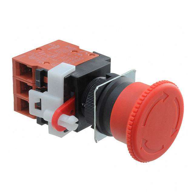
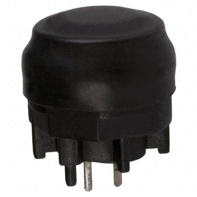
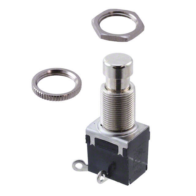
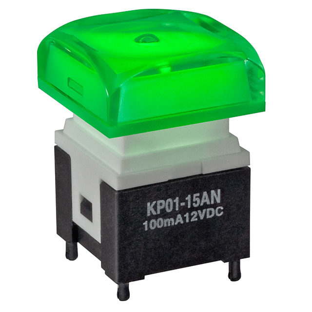
- 型号: 172
- 制造商: Carling Technologies
- 库位|库存: xxxx|xxxx
- 要求:
| 数量阶梯 | 香港交货 | 国内含税 |
| +xxxx | $xxxx | ¥xxxx |
查看当月历史价格
查看今年历史价格
172产品简介:
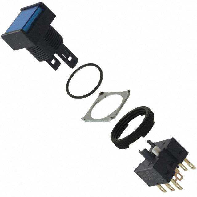
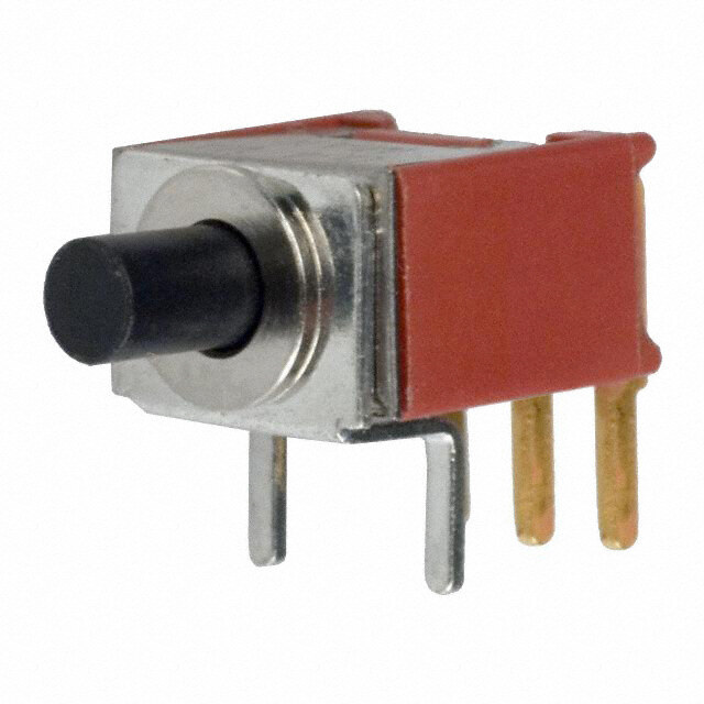
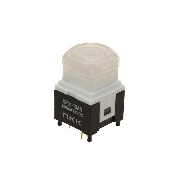
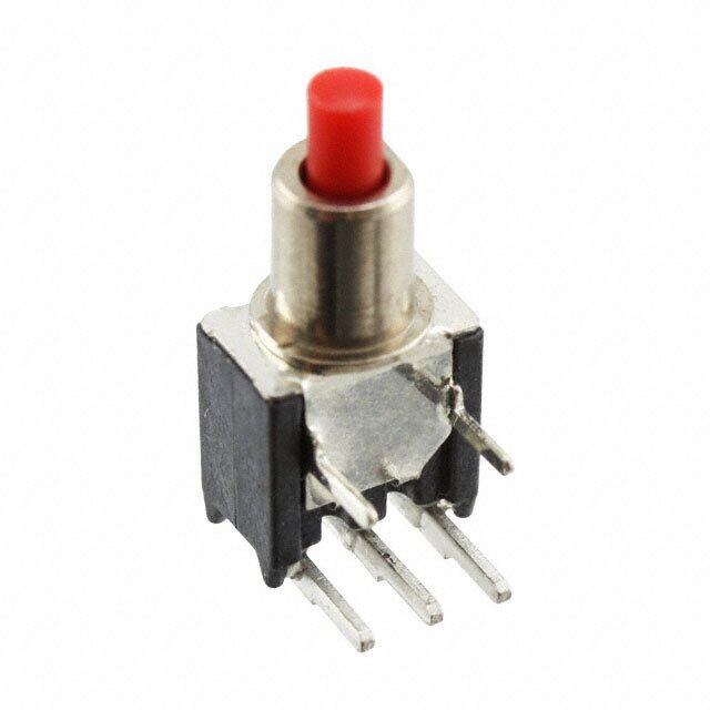
ICGOO电子元器件商城为您提供172由Carling Technologies设计生产,在icgoo商城现货销售,并且可以通过原厂、代理商等渠道进行代购。 172价格参考。Carling Technologies172封装/规格:按钮开关, 标准 按钮开关 SPST-NO 面板安装,后部。您可以下载172参考资料、Datasheet数据手册功能说明书,资料中有172 详细功能的应用电路图电压和使用方法及教程。
| 参数 | 数值 |
| 产品目录 | |
| 描述 | SWITCH PUSH SPST-NO 15A 125V按钮开关 1 POLE OFF(ON) SCREW |
| 产品分类 | |
| 品牌 | Carling Technologies |
| 产品手册 | |
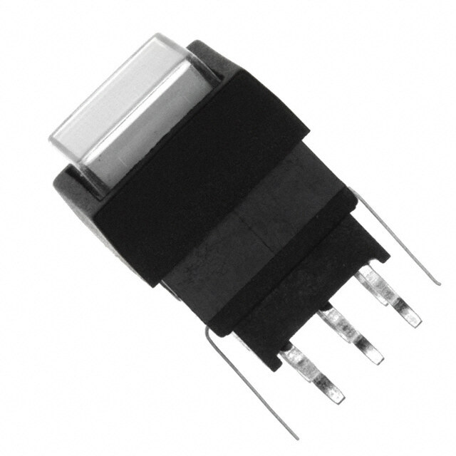
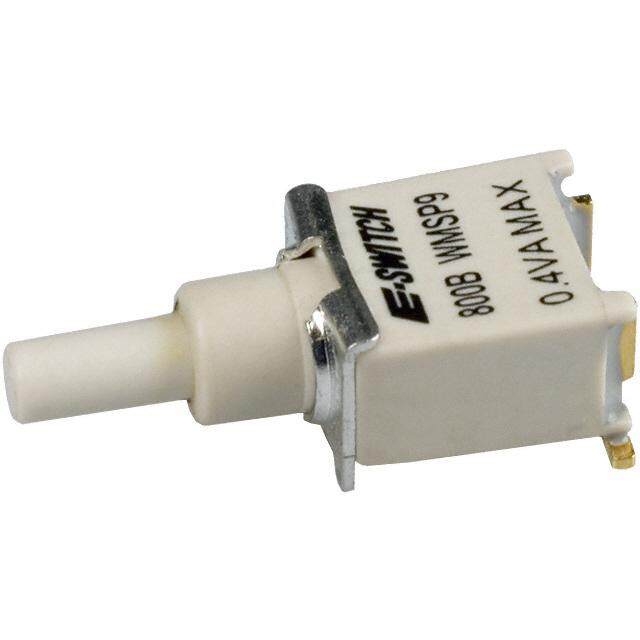
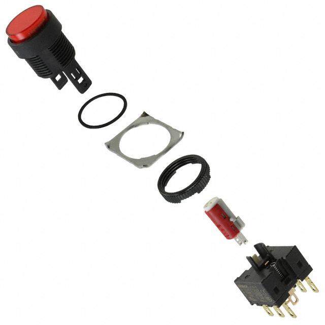
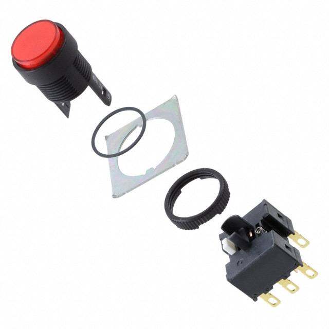
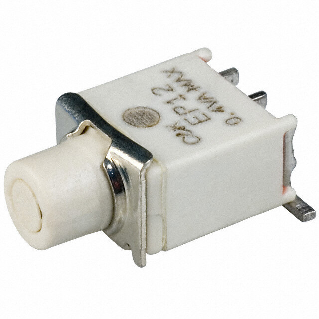
| 产品图片 |
|
| rohs | 符合RoHS无铅 / 符合限制有害物质指令(RoHS)规范要求 |
| 产品系列 | 按钮开关,Carling Technologies 172172 |
| mouser_ship_limit | 该产品可能需要其他文件才能进口到中国。 |
| 数据手册 | |
| 产品型号 | 172 |
| 产品目录绘图 |
|
| 产品目录页面 | |
| 产品种类 | |
| 侵入防护 | - |
| 其它名称 | 432-1208 |
| 包装 | 散装 |
| 商标 | Carling Technologies |
| 安装孔 | Round |
| 安装孔直径 | 12.7 mm |
| 安装类型 | 面板安装,后部 |
| 安装风格 | Panel |
| 工作温度 | 0°C ~ 85°C |
| 工厂包装数量 | 500 |
| 开关功能 | 关-瞬时 |
| 执行器 | Plunger |
| 机械寿命 | 100,000 次循环 |
| 标准包装 | 100 |
| 照明电压(标称值) | - |
| 照明类型,颜色 | - |
| 特性 | - |
| 电压额定值AC | 125 V |
| 电气寿命 | 25,000 次循环 |
| 电流额定值 | 15 A |
| 电路 | SPST-NO |
| 相关产品 | /product-detail/zh/NC3030%202/335-1008-ND/340285/product-detail/zh/NC3030%204/335-1010-ND/340287/product-detail/zh/728-15907/432-1261-ND/3025011/product-detail/zh/728-15946/432-1262-ND/3025015/product-detail/zh/380-08602/432-1249-ND/3025029/product-detail/zh/380-08693/432-1250-ND/3025035/product-detail/zh/380-08810/432-1251-ND/3025038/product-detail/zh/C1231%2F42/335-1142-ND/3712288 |
| 端子密封 | Unsealed |
| 端子类型 | 螺丝端子 |
| 端接类型 | Screw |
| 类型 | 标准 |
| 系列 | 172 |
| 致动器类型 | 圆形,按钮 |
| 触点形式 | SPST |
| 触点电镀 | Nickel |
| 面板开口尺寸 | 圆形 - 12.70mm 直径 |
| 颜色-致动器/盖帽 | 银 |
| 额定电压-AC | 125V |
| 额定电压-DC | - |
| 额定电流 | 15A(AC) |



- 商务部:美国ITC正式对集成电路等产品启动337调查
- 曝三星4nm工艺存在良率问题 高通将骁龙8 Gen1或转产台积电
- 太阳诱电将投资9.5亿元在常州建新厂生产MLCC 预计2023年完工
- 英特尔发布欧洲新工厂建设计划 深化IDM 2.0 战略
- 台积电先进制程称霸业界 有大客户加持明年业绩稳了
- 达到5530亿美元!SIA预计今年全球半导体销售额将创下新高
- 英特尔拟将自动驾驶子公司Mobileye上市 估值或超500亿美元
- 三星加码芯片和SET,合并消费电子和移动部门,撤换高东真等 CEO
- 三星电子宣布重大人事变动 还合并消费电子和移动部门
- 海关总署:前11个月进口集成电路产品价值2.52万亿元 增长14.8%

PDF Datasheet 数据手册内容提取
Series 172 DPDT Non-Latching Commercial Electromechanical Relay CENTIGRID® COMMERCIAL RELAYS DPDT SERIES RELAY TYPE 172 DPDT basic relay 172D DPDT relay with internal diode for coil transient suppression DESCRIPTION The 172 Centigrid® relay is an ultraminiature, hermetically sealed, • High force/mass ratios for resistance to shock and vibration. armature relay for commercial applications. Its low profile height (.280”) • Advanced cleaning techniques provide maximum assurance of and .100” grid spaced terminals, which preclude the need for spreader pads, internal cleanliness. make it an ideal choice where extreme packaging density and/or close PC • Precious metal alloy contact material with gold plating assures excellent board spacing are required. high current and dry circuit switching capabilities. The basic operating concept and internal structure are similar to The Series 172 relay has an internal discrete silicon diode for coil transient Teledyne’s DPDT 114 Centigrid® relay. Unique construction features and suppression. manufacturing techniques provide overall high reliability and excellent resistance to environmental extremes: By virtue of its inherently low intercontact capacitance and contact circuit losses, the 172 relay is an excellent subminiature RF switch for The 172 feature: frequencies well into the UHF spectrum (see Figure 1). Applications • All welded construction. include telecommunications, test instruments, mobile communications, • Unique uni-frame design providing high magnetic efficiency and attenuators, and automatic test equipment. mechanical rigidity. Part Numbering System 172 Z M4 - 26 / S Q Q = Solder-Coated Leads1 Relay Series G = Gold-Plated Leads (RoHS Compliant) R = RoHS Compliant Solder2 Ground Pin Option (See Appendix) S = 0.187” Leads Pad Option No Suffi x = 0.75” Leads (See Appendix) Nominal Coil Voltage ENVIRONMENTAL AND (26 = 26.5 V, See Page 2 for more Voltages) PHYSICAL SPECIFICATIONS INTERNAL CONSTRUCTION Temperature –65°C to +125°C (Ambient) Vibration 10 g’s to 500 Hz (General Note I) Shock 30 g’s, (General Note I) 6ms half sine Enclosure Hermetically sealed Weight 0.15 oz. (4.3g) max. © 2019 TELEDYNE RELAYS (800) 284-7007 • www.teledynerelays.com 172 Page 1 172\112019\Q4
Series 172 DPDT Non-Latching Commercial Electromechanical Relay SERIES 172 GENERAL ELECTRICAL SPECIFICATIONS (@25°C) Contact Arrangement 2 Form C (DPDT) Rated Duty Continuous Contact Resistance 0.15 Ω max. Resistive: 1 A/ 28 Vdc Inductive: 200 mA/ 28 Vdc (320mH) Contact Load Rating Lamp: 100 mA / 28 Vdc (320mH) Low level: 10 to 50 μA @ 10 to 50 mV 5,000,000 cycles (typical) at low level Contact Life Ratings 500,000 cycles (typical) at 0.5 A / 28 Vdc resistive 100,000 cycles min. at all other loads specifi ed above Contact Overload Rating 2 A / 28 Vdc Resistive (100 cycles min.) Contact Carry Rating Contact Factory Operate Time 6.0 msec max. at nominal rated coil voltage Release Time 172: 3.0 ms max. 172D: 6.0 ms max. Intercontact Capacitance 0.4 pf typical Insulation Resistance 1,000 MΩ min. between mutually isolated terminals Dielectric Strength 300 Vrms (60 Hz) @ atmospheric pressure Negative Coil Transient (Vdc) 2.0 Vdc Max. Diode P.I.V. (Vdc) 60 Vdc Min. DETAILED ELECTRICAL SPECIFICATIONS (@25°C) 172-5 172-12 172-26 BASE PART NUMBERS (172, 172D) 172D-5 172D-12 172D-26 Nom. 5.0 12.0 26.5 Coil Voltage Max. 5.8 16.0 32.0 Coil Resistance (Ohms ±20%) 64 400 1600 Pick-up Voltage (Vdc, Max.) Pulse Operation 3.8 9.0 18.0 Coil Operating Power at Nominal Voltage (mW) 405 360 440 172 Page 2 SPECIFICATIONS ARE SUBJECT TO CHANGE WITHOUT NOTICE © 2019 TELEDYNE RELAYS 172\112019\Q4
Series 172 DPDT Non-Latching Commercial Electromechanical Relay SERIES 172 OUTLINE DIMENSIONS (9.52) (Viewed From Terminals) SCHEMATIC DIAGRAMS 172 172D NOTES: 1. RELAY CONTACTS WILL EXHIBIT NO CHATTER IN EXCESS OF 10 ΜSEC OR TRANSFER IN EXCESS OF 1 ΜSEC. 2. “TYPICAL” CHARACTERISTICS ARE BASED ON AVAILABLE DATA AND ARE BEST ESTIMATES. NO ON-GOING VERIFICATION TESTS ARE PERFORMED. 3. UNLESS OTHERWISE SPECIFIED, PARAMETERS ARE INITIAL VALUES. 4. RELAYS CAN BE SUPPLIED WITH A SPACER PAD. SEE APPENDIX. © 2019 TELEDYNE RELAYS (800) 284-7007 • www.teledynerelays.com 172 Page 3 172\112019\Q4
APPENDIX A : Spacer Pads Pad designation and Dim. H Height For use with the following: bottom view dimensions Max. ER412 .295 (7.49) Ø.150 [3.81] (REF) 712, RF300, RF, RF700, RF703 .300 (7.62) Dim H ER422, 722 .305 (7.75) MAX ER432 .400 (10.16) 732, RF303 .410 (10.41) “M4” Pad for TO-5 RF312 .350 (8.89) ER411 .295 (7.49) Dim H MAX RF311 .300 (7.62) RF331 .410 (10.41) “M4” Pad for TO-5 172 .305 (7.75) ER114, J114 .300 (7.62) Dim H MAX ER134, J134 .400 (10.16) RF100 .315 (8.00) RF103 .420 (10.67) “M4” Pad for Centigrid® .156 122C, A152 .320 (8.13) [3.96] (REF) ER116C, J116C .300 (7.62) Dim H MAX .256 ER136C, J136C .400 (10.16) [6.5] (REF) RF180 .325 (8.25) A150 .305 (7.75) “M9” Pad for Centigrid® Notes: 1. Spacer pad material: Polyester fi lm. 2. To specify an “M4” or “M9” spacer pad, refer to the mounting variants portion of the part numbering example in the applicable datasheet. 3. Dimensions are in inches (mm). 4. Unless otherwise specifi ed, tolerance is ± .010” (.25 mm). 5. Add 10 mΩ to the contact resistance shown in the datasheet. 6. Add 0.01 oz. (0.25 g) to the weight of the relay assembly shown in the datasheet. Page 4 (800) 284-7007 • www.teledynerelays.com • +44 (0) 1236 453124 • www.teledyne-europe.com © 2016 TELEDYNE RELAYS
APPENDIX A : Spreader Pads Pad designation and Dim. H Height For use with the following: bottom view dimensions Max. ER411T, ER412, J412 .388 (9.86) .370 [9.4] MAX SQ .100 [2.54] Dim H 712 .393 (9.99) MAX .150 .014 [3.81] [0.36] .300 (REF) [7.62] ER432, J432 .493 (12.52) .100 [2.54] .370 [9.4] 732 .503 (12.78) .200 MIN [5.08] J421, J422, ER422, 722 .398 (10.11) “M” Pad 5/ 6/ Notes: 1. Spreader pad material: Diallyl Phthalate. 2. To specify an “M”, “M2” or “M3” spreader pad, refer to the mounting variants portion of the part number example in the applicable datasheet. 3. Dimensions are in inches (mm). 4. Unless otherwise specifi ed, tolerance is ± .010” (0.25 mm). 5/. Add 25 mΩ to the contact resistance shown in the datasheet. 6/. Add .01 oz. (0.25 g) to the weight of the relay assembly shown in the datasheet. 7/. Add 50 mΩ to the contact resistance shown in the datasheet. 8/. Add 0.025 oz (0.71 g) to the weight of the relay assembly shown in the datasheet. 9/. M3 pad to be used only when the relay has a center pin (e.g. ER411M3-12A, 722XM3-26.) © 2016 TELEDYNE RELAYS SPECIFICATIONS SUBJECT TO CHANGE WITHOUT NOTICE Page 5
APPENDIX A : Ground Pin Positions NOTES 1. Terminal views shown Indicates ground pin position 2. Dimensions are in inches (mm) Indicates glass insulated lead position 3. Tolerances: ± .010 (±.25) unless otherwise specifi ed 4. Ground pin positions are within .015 (0.38) dia. of true position Indicates ground pin or lead position 5. Ground pin head dia., 0.035 (0.89) ref: height 0.010 (0.25) ref. depending on relay type 6. Lead dia. 0.017 (0.43) nom. Page 6 (800) 284-7007 • www.teledynerelays.com • +44 (0) 1236 453124 • www.teledyne-europe.com © 2016 TELEDYNE RELAYS
Mouser Electronics Authorized Distributor Click to View Pricing, Inventory, Delivery & Lifecycle Information: T eledyne Relays: 172-12 172-26 172-5 172D-12 172D-26 172D-5 172DM4-12 172DM4-26 172M4-5 400-192-10 400-192-59 172-12/G

 Datasheet下载


