ICGOO在线商城 > 连接器,互连器件 > 刀片式电源连接器 - 触头 > 1604038-1

 Datasheet下载
- 型号: 1604038-1
- 制造商: CORCOM/TYCO ELECTRONICS
- 库位|库存: xxxx|xxxx
- 要求:
| 数量阶梯 | 香港交货 | 国内含税 |
| +xxxx | $xxxx | ¥xxxx |
查看当月历史价格
查看今年历史价格
1604038-1产品简介:
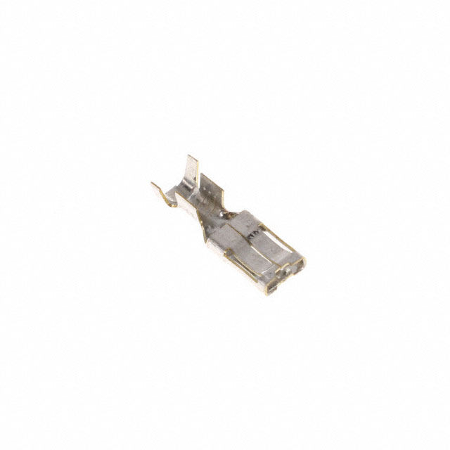
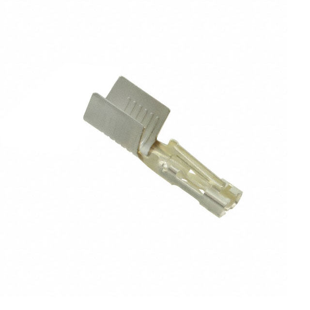
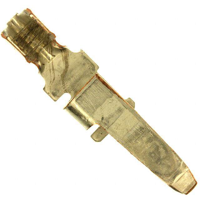
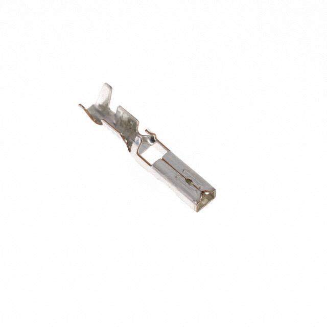
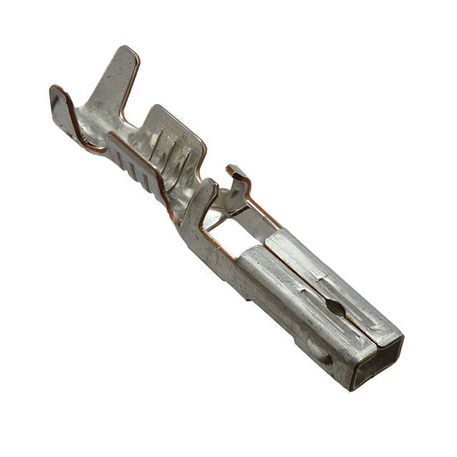
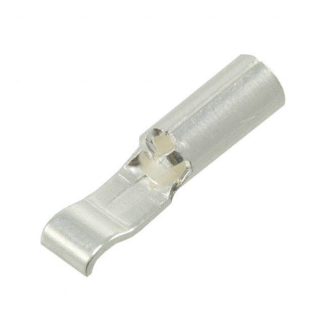
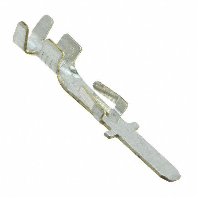
ICGOO电子元器件商城为您提供1604038-1由CORCOM/TYCO ELECTRONICS设计生产,在icgoo商城现货销售,并且可以通过原厂、代理商等渠道进行代购。 1604038-1价格参考¥25.11-¥39.87。CORCOM/TYCO ELECTRONICS1604038-1封装/规格:刀片式电源连接器 - 触头, Blade Contact 1/0 AWG Crimp Non-Gendered Silver。您可以下载1604038-1参考资料、Datasheet数据手册功能说明书,资料中有1604038-1 详细功能的应用电路图电压和使用方法及教程。
| 参数 | 数值 |
| 3D型号 | http://www.te.com/commerce/DocumentDelivery/DDEController?Action=srchrtrv&DocNm=1604038-1&DocType=Customer+View+Model&DocLang=English |
| 产品目录 | |
| 描述 | TERM BLADE NON-GENDR 1/0AWG |
| 产品分类 | |
| 品牌 | TE Connectivity |
| 数据手册 | http://www.te.com/commerce/DocumentDelivery/DDEController?Action=srchrtrv&DocNm=1604038&DocType=Customer+Drawing&DocLang=English |
| 产品图片 |
|
| 产品型号 | 1604038-1 |
| rohs | 无铅 / 符合限制有害物质指令(RoHS)规范要求 |
| RoHS指令信息 | http://www.te.com/commerce/alt/SinglePartSearch.do?PN=1604038-1&dest=stmt点击此处下载产品Datasheet |
| 产品系列 | 电源系列 175/180,AMP |
| 其它名称 | 16040381 |
| 包装 | 散装 |
| 标准包装 | 400 |
| 类型 | 机制 |
| 线规 | 1/0 AWG |
| 触头材料 | 铜合金 |
| 触头端接 | 压接 |
| 触头类型 | 无公型或母型区分 |
| 触头镀层 | 银 |
| 触头镀层厚度 | - |
| 配用 | /product-detail/zh/1604042-6/A116445-ND/4730358/product-detail/zh/1604062-1/A112475-ND/2329852/product-detail/zh/1604062-5/A112479-ND/2329851/product-detail/zh/1604062-4/A112478-ND/2329850/product-detail/zh/1604062-3/A112477-ND/2329849/product-detail/zh/1604037-2/A112462-ND/2329811/product-detail/zh/1604062-2/A112476-ND/1149299/product-detail/zh/1604037-5/A112464-ND/1149293/product-detail/zh/1604037-3/A112463-ND/1149292/product-detail/zh/1604037-1/1604037-1-ND/1149291/product-detail/zh/1604037-4/1604037-4-ND/1131458 |


- 商务部:美国ITC正式对集成电路等产品启动337调查
- 曝三星4nm工艺存在良率问题 高通将骁龙8 Gen1或转产台积电
- 太阳诱电将投资9.5亿元在常州建新厂生产MLCC 预计2023年完工
- 英特尔发布欧洲新工厂建设计划 深化IDM 2.0 战略
- 台积电先进制程称霸业界 有大客户加持明年业绩稳了
- 达到5530亿美元!SIA预计今年全球半导体销售额将创下新高
- 英特尔拟将自动驾驶子公司Mobileye上市 估值或超500亿美元
- 三星加码芯片和SET,合并消费电子和移动部门,撤换高东真等 CEO
- 三星电子宣布重大人事变动 还合并消费电子和移动部门
- 海关总署:前11个月进口集成电路产品价值2.52万亿元 增长14.8%
PDF Datasheet 数据手册内容提取
Power Connectors & Interconnection Systems ELCON Drawer Series Connectors True Hot-Plug, Blind-Mating Mixed Signal and Power Connectors Product Facts ■ Wide variety of contact sizes and styles from 1 Amp signals up to power contacts rated at up to 200 Amps each ■ Sequenced contacts for “mate-first-break-last” operation s ct ■ Floating panel-mount u connectors float up to d o +/- 2 mm r P d ■ High durability specific e nt products ranging from u 100 to 1000 mate/un-mate o M cycles e bl ■ Customizable products a allow the freedom to add or C remove power or signal contacts to meet specific application requirement ■ Most products recognized to US and Canadian requirements under the Component Recognition program of Underwriters Laboratories File No. Tyco Electronics offers a product line names in these The contacts are the core E28476 wide selection of blind- two categories are: of the ELCON drawer AND ® mateable “drawer” connec- series connectors. For cost R C US tors to suit modular High Power Drawer Connectors sensitive applications the equipment designs. The ■ ELCON Drawer Series different hybrid drawer term “drawer connector” Connectors connectors offer a wide Typical Applications was created to describe a variety of shapes and sizes Low Power Drawer Connectors ■ Low noise power supplies cabinet drawer where the aimed at keeping cost mini- ■ AMP Drawer Series ■ Switch-mode power connector is installed at the mized and still providing a Connectors supplies (SMPS) back of the drawer and is reliable separable interface. mated by closing the ■ Mini Power Drawer ■ Power factor-correcting Regardless of the applica- (PFC) power supplies drawer. Since the “drawer” ■ Blind-mate Drawer tion, Tyco Electronics offers is often times made with a Connectors a wide variety of power & ■ Systems requiring mounting somewhat loose fit — to ■ Hybrid Mini Drawer signal blind-mateable to backplane or chassis enable easy opening and Connectors drawer connectors. closing, the drawer connec- ■ Redundant (N + 1) power Some of the benefits of the tor must provide sufficient systems power drawer connectors self-alignment and ideally a Need more information? ■ “Live” hot-plug power floating connection to the from Tyco Electronics are supplies cabinet or drawer to keep the robustness of the Call Technical Support at housing designs and the the numbers listed below. ■ All ELCON drawer the connection from binding. durability of the contacts. connectors in this section The power drawer connec- High-end applications such Technical Support is staffed are RoHS compliant tors in this catalog are as networking switches and with specialists well versed in all TycoElectronics divided into two separate servers want the lowest products. They can provide categories: high power possible voltage drop you with: drawers and low power across the connector. drawers. Specifically, the For these applications the ■ Technical Support high conductivity screw- ■ Catalogs machined contacts with ■ Technical Documents Technical Documents either gold or silver plating ■ Product Samples Product Specification offer the best performance. 108-2285 ■ TycoElectronics Application Specification Authorized Distributor 114-13206 Locations 62 Catalog 1773096 Dimensions are in inches and Dimensions are shown for USA: 1-800-522-6752 South America: 55-11-2103-6000 Revised 2-10 millimeters unless otherwise reference purposes only. Canada: 1-905-470-4425 Hong Kong: 852-2735-1628 specified. Values in brackets Specifications subject Mexico: 01-800-733-8926 Japan: 81-44-844-8013 www.tycoelectronics.com are metric equivalents. to change. C. America: 52-55-1106-0803 UK: 44-(0)8002-67666
Power Connectors & Interconnection Systems ELCON Drawer Series Connectors True Hot-Plug, Blind-Mating Mixed Signal and Power Connectors (Continued) Probe-proof Double Signal/Power Sequencing Regulatory Agency CROWNBAND Contacts Certifications All signal and some power The size #0 contacts used contacts are available in TycoElectronics ELCON in the Top Drawer, Double various lengths to allow drawer series connectors Drawer, DualPower and multiple levels of sequenc- have been evaluated and QuadPower connectors ing, thus giving the engineer found to comply with the are also available in a further design flexibility. UL1977 standard and the probe-proof double CSA standard C22.2 No. Mating Polarization CROWNBAND version. 182.3-M1987. These contacts are spe- To provide for positive Ca cially suited for operator- housing mating of Twyocrok Ewliethc ttrhoen iccuss ctoamn earl stoo ble 3 mm Diameter Test Probe in sthearvt irceeqdu ipreo wexetrr as uspapfeliteys ciso pnrnoevcidtoerds, inp othlaer izfoartmio no f obtain application-specific Mo Accordance with IEC 435 regulatory certifications if u Protective Cap (insulator) protection. mproel-dinesdta-ilnle gdu gidueid peo psitnss o.r needed. ® nte d C US P r o d u Wide Array of ELCON drawer connectors to PCB, and internal/ c ts Standard Contacts support various termination external threads for termina- styles, including crimp for tion to lugs and/or busbars. cable, solder tail and com- See table below for details. pliant press-fit for mounting Termination Contact Size Threaded PC Tail Press-fit Crimp Internal External #20 (cid:129) (cid:129) (cid:129) #16 (cid:129) (cid:129) (cid:129) #12 (cid:129) (cid:129) (cid:129) #8 (cid:129) (cid:129) (cid:129) (cid:129) (cid:129) #4 (cid:129) (cid:129) (cid:129) #0 (cid:129) (cid:129) (cid:129) Application-Specific Designs If none of our standard work closely with your engi- TycoElectronics produces agency evaluations and drawer connectors neers to fully understand prototypes that perform even as pre-production satisfies your requirements, the design requirements both electrically and components, allowing the TycoElectronics can and develop an intercon- mechanically the same as shortest lead time from develop an ELCON con- nect solution that meets production parts. These concept to manufacturing nector design specific to your stated needs. After the machined parts are used in the industry. your application. We will concept and design stages, for testing, regulatory Concept Design Prototypes Production Tyco Electronics engineers A sketch drawing of the The design is frozen and By the time the customer work closely with the cus- design concept is created work on the mold tools starts. is ready for production, all tomer to fully understand for customer review, and the Meanwhile, TycoElectronics requirements for release the design requirements. design is finalized only when builds prototypes that are to production, such as it fully meets the require- identical to the production qualification and regulatory ments of the customer. parts. agency approval, have been cleared. 63 Catalog 1773096 Dimensions are in inches and Dimensions are shown for USA: 1-800-522-6752 South America: 55-11-2103-6000 Revised 2-10 millimeters unless otherwise reference purposes only. Canada: 1-905-470-4425 Hong Kong: 852-2735-1628 specified. Values in brackets Specifications subject Mexico: 01-800-733-8926 Japan: 81-44-844-8013 www.tycoelectronics.com are metric equivalents. to change. C. America: 52-55-1106-0803 UK: 44-(0)8002-67666
Power Connectors & Interconnection Systems How to Tailor Your ELCON Drawer Connector If you selected a standard drawer connector for your appli- this purpose. Complete a form for the pin and socket side cation, before placing an order you need to specify your of your connector as indicated in the instructions and fax it application-specific requirements, such as housing type, to your Tyco Electronics sales engineer. We will issue a contact loading, and termination style. Layout forms for all unique part number specific to your configuration, which standard drawer connectors, such as the one shown below, you can then use to place orders. Samples and customer are available online at http://www.tycoelectronics.com or drawings are also available upon request. can be obtained from Tyco Electronics customer service for Pin Assembly ENTER CUSTOMER INFORMATION 1. Choose one housing from the Pin Housing Selection Menutable. Place Company Location s an X in the appropriate guide pin circles, if guide pins are required. uct 2. Write the total quantity of each pin contact you require for each pin Contact Name Title d assemblyin the Qtycolumn of the Pin Contact Selection Menutable. o r 3. Crimp contacts are shipped uninstalled. Threaded and PCB tail Telephone Fax P d contacts are installed by TycoElectronics; enter the letter reference e of the desired contact in the appropriate contact positions on the Email Address nt drawing: e.g., if you need a size #20 premate PCB tail standard con- Mou tact to be installed in contact position #10, write “Q” in circle #10. I am: ❏❏ECnodn turascetr manufacturer (end user: ) 4. Sign, date and send the completed form to your local TycoElectronics ble Sales Engineer. Signature Today’s Date a Pin Connector (Rear Face) Annual Quantity Required C Pin Contact Insertion Side Pin Connector Rear Face Cavity Identification Submit to your local TycoElectronics Sales Engineer. G1 G2 Pin Housing Selection Menu Check Part Number Description One 1648183-1 Housing without guides Housing with guides (#6-32 thread) Housing with guides (M3 x 0.5 thread) 1 2 Size #0 Pin Contact Selection Menu Size Ref. Part Number Termination Style & Pin Length Qty. A = 1766811-1 Crimp B = 1766819-1 Probe Proof, crimp C = 1766230-1 1/4-20 Internal Thread D = 1766274-1 M6 x 1 Internal Thread E = 1766269-1 Probe Proof, 1/4-20 Internal Thread 3 4 5 6 7 8 9 10 #0 F = 1766275-1 Probe Proof, M6 x 1 Internal Thread 11 12 13 14 15 16 17 18 G = 1766268-1 1/4-20 External Thread Size #20 H = 1766231-1 M6 x 1 External Thread 19 20 21 22 23 24 25 26 J = 1766270-1 Probe Proof, 1/4-20 External Thread K = 1766276-1 Probe Proof, M6 x 1 External Thread 27 28 29 30 31 32 33 34 L = 1650155-1 Crimp, standard M = 1650161-1 Crimp, premate N = 1650162-2 Crimp, postmate 35 36 37 38 39 40 #20 Size #16 P = 1650283-1 PCB tail, standard Q = 1650065-1 PCB tail, premate 41 42 43 44 45 46 R = 1650226-1 PCB tail, postmate S = 1766196-1 Crimp, standard T = 1766198-1 Crimp, premate U = 1766199-2 Crimp, postmate #16 47 48 49 V = 1766222-1 PCB tail, standard W = 1766223-1 PCB tail, premate X = 1766818-1 PCB tail, postmate Size #12 or Y = 1766193-1 Crimp, standard #12HP Z = 1766195-1 Crimp, premate 50 51 52 AA = 1766196-1 Crimp, postmate #12 AB = 1766245-1 PCB tail, standard AC = 1766250-1 PCB tail, premate AD = 1766249-1 PCB tail, postmate AE = 1650153-2 Crimp, standard, Hot-Plug #12 Hot- AF = 1650156-2 Crimp, premate, Hot-Plug G3 G4 Plug AG = 1650060-2 PCB tail, standard, Hot-Plug AH = 1650074-3 PCB tail, premate, Hot-Plug Crimp and Threaded contacts are removable. PCB tail contacts are non-removable. Float-Mount Shoulder Screw Part Number Description Qty. Top Assembly Part Number Assigned by TycoElectronics 1650399-1 Screw, No 10-32 UNC 2A 1650401-1 Screw, M5 x 0.8 64 Catalog 1773096 Dimensions are in inches and Dimensions are shown for USA: 1-800-522-6752 South America: 55-11-2103-6000 Revised 2-10 millimeters unless otherwise reference purposes only. Canada: 1-905-470-4425 Hong Kong: 852-2735-1628 specified. Values in brackets Specifications subject Mexico: 01-800-733-8926 Japan: 81-44-844-8013 www.tycoelectronics.com are metric equivalents. to change. C. America: 52-55-1106-0803 UK: 44-(0)8002-67666
Power Connectors & Interconnection Systems ELCON Drawer Connector Mounting All ELCON drawer series connectors can be fix-mounted or float-mounted using the designated shoulder screws to allow improved gatherability for blind-mating of the connector. Panel cut out dimensions are shown on the customer drawing specific to your ELCON drawer connector. Panel Float Mounting When float-mounting to a panel or chassis, use the stainless steel shoulder screws specified in the layout sheet or customer drawing specific to your ELCON drawer connector. Shown in the sketch below is an example of how the Top Drawer connector is float-mounted to a panel. C Float-Mount of Top Drawer (Example) a b le M o u n te d Mounting P Flange r o d u c ts Panel (Ref) Shoulder Guide Pin Screw Screw Description Part Number Used On #10-32 UNF 2A Thread 1650399-1 Top and Double Drawer, Dual and QuadPower, M5 x 0.8 Metric Thread 1650401-1 In-Line QuadPower, W5 Drawer #8-32 UNF 2A Thread 1650402-1 #6-32 UNF 2A Thread 1650106-1 All Other Drawers M4 x 0.7 Metric Thread 1650589-1 Panel Fix Mounting As a rule of thumb, ELCON drawer connectors can be fix-mounted to a panel, in two ways: (1) by attaching a screw through the top and bottom mounting flange of the housing; or (2) by attaching a screw into a threaded guide pin (for those connectors that have one). An example of each case is shown in the sketches below. Screw Through Mounting Flange of Housing Screw Into Thread of Guide Pin (When Applicable) Fix to the panel by attaching a commercially available You can optionally fix-mount housings that have a guide screw and a washer through the top and bottom mounting pin by attaching a commercially available screw and flange of the housing. washer into the thread on the back of the guide pin, as shown in the figures below. Commercially Internally threaded available screw (6-32) guide pin and washer Commercially available screw and washer Guide pin #6-32 or M3 x 0.5 screw .25 [6.35] Note:All part numbers are RoHS compliant. 65 Catalog 1773096 Dimensions are in inches and Dimensions are shown for USA: 1-800-522-6752 South America: 55-11-2103-6000 Revised 2-10 millimeters unless otherwise reference purposes only. Canada: 1-905-470-4425 Hong Kong: 852-2735-1628 specified. Values in brackets Specifications subject Mexico: 01-800-733-8926 Japan: 81-44-844-8013 www.tycoelectronics.com are metric equivalents. to change. C. America: 52-55-1106-0803 UK: 44-(0)8002-67666
Power Connectors & Interconnection Systems ELCON Drawer Connector Mounting (Continued) Strain Relief and Wire Dress If required, wires can be bundled together and supported with cable ties. Wires must not be stretched or confined in any way that would restrict the floating action of the con- nectors. Therefore, the wires must remain perpendicular to the connector and avoid an excessively sharp bend radius. The minimum recommended distance for the cable tie, and the minimum bend radius of a wire bundle are shown in the figure to the right. s ct u d PCB Fix Mounting o r P When mounting to a PC board, the connector standoffs must be seated on the board. Hold-downs are recommended to d e provide stability during the soldering procedure. PCB-mount hole patterns are shown on the customer drawing specific nt to your ELCON drawer connector. u o M e bl Flush PCB-Mount Drawer Connectors Drawer Connectors with Cabled AC IN a C .020 [0.51] PC Board (Ref) Wire Connector Standoffs .020 [0.51] Connector Engagement To provide for proper mating of the connector when the power supply unit is fully engaged into the system, the gap between the pin and socket (shown as dimension “A” in the sketch below) must be within the limit specified in the customer drawing for your ELCON drawer connector. Failure to meet this requirement may compromise contact wipe. Refer to the customer drawing for details. ELCON drawer connectors are polarized and will only mate in the correct orientation (see sketch below). Rib in Guide Post Cavity Notch in Guide Post 66 Catalog 1773096 Dimensions are in inches and Dimensions are shown for USA: 1-800-522-6752 South America: 55-11-2103-6000 Revised 2-10 millimeters unless otherwise reference purposes only. Canada: 1-905-470-4425 Hong Kong: 852-2735-1628 specified. Values in brackets Specifications subject Mexico: 01-800-733-8926 Japan: 81-44-844-8013 www.tycoelectronics.com are metric equivalents. to change. C. America: 52-55-1106-0803 UK: 44-(0)8002-67666
Power Connectors & Interconnection Systems ELCON Drawer Connector Tooling Insertion/Removal (I/R) Tools:Industry standard plastic I/R tooling is compatible with all crimp contacts for pin and socket removal. The following tools are available from TycoElectronics. I/R Tools Part Numbers Size Color Code 1643917-1 Size #20 I/R tool Red/White 1643916-1 Size #16 I/R tool Blue/White 1643915-1 Size #12 I/R tool Yellow/White 1643914-1 Size #8 removal tool Red 1643922-1 Size #4 removal tool Blue C a 1643921-1 Size #0 removal tool Light Yellow b le Note:PCB tail contacts are non-removable. M o u n te Wire strip length:If inserting stranded wire into crimp style contacts, please use the table d P below to determine the proper strip length of the wire. r o d u c Contact Size Wire Size AWG “L” + .020 [0.51] ts inches mm #20 #24 - #20 0.210 5.33 #16 #20 - #16 0.270 6.86 #12 #14 - #12 0.270 6.86 #8 #10* - #8 0.500 12.70 #4 #6* - #4 0.500 12.70 #0 #2* - #0 0.600 15.24 *Ref: MS3348 “Contact Bushing, Electric, Wire Barrel” Crimp Tools:The following table lists applicable MIL-STD crimp tools for contacts Size Type MIL-STD Part Number Crimp Tool M22520/1-01 601967-1 12 - 24 Turret head/locator M22520/1-02 601967-2 Crimp Tool M22520/23-01 — 8 - 10 Indenter head M22520/23-02 — Locator M22520/23-09 — Crimp Tool M22520/23-01 — 4 Indenter head M22520/23-04 — Locator M22520/23-11 — Crimp Tool M22520/23-01 — 0 Indenter head M22520/23-05 — Locator M22520/23-13 — Crimp Termination Wire Sizes:The following table shows crimp rear release contacts and their respective wire sizes when crimped with applicable industry standard terminal tools. Wire Range Contact Size AWG mm2 #20 20 - 24 0.241 - 0.616 #16 16 - 18 0.963 - 1.23 #12 12 - 14 1.94 - 2.98 #8 10 - 8 4.74 - 8.61 #4 4 (1) 21.60 #0 1/0 53.00 Note:(1)Consult Tyco Electronics for smaller wire sizes in #4 contacts Note:All part numbers are RoHS compliant. 67 Catalog 1773096 Dimensions are in inches and Dimensions are shown for USA: 1-800-522-6752 South America: 55-11-2103-6000 Revised 2-10 millimeters unless otherwise reference purposes only. Canada: 1-905-470-4425 Hong Kong: 852-2735-1628 specified. Values in brackets Specifications subject Mexico: 01-800-733-8926 Japan: 81-44-844-8013 www.tycoelectronics.com are metric equivalents. to change. C. America: 52-55-1106-0803 UK: 44-(0)8002-67666
Power Connectors & Interconnection Systems ELCON Drawer Product Specifications Materials Housing Polyester, 30% glass-filled, UL 94V-0 black Crimp Contacts High conductivity copper alloy PCB Tails Brass Socket Contact Hoods (when applicable) 305 corrosion resistant steel Size #12 hoods, Hot-Plug Beryllium copper Crown contacts Beryllium copper Plating Size #20 and #12HP Gold plated over nickel Sizes #0, #4, #8, #16 and non-HP #12 Silver plated over nickel cts Hot-Plug hoods and pin contacts Gold plated over nickel u Socket Contact Hoods (when applicable) Passivated d o Mechanical r P d Size #20 0.2 lb. 0.09 kg e Size #16 2.3 lb. 1.04 kg unt Typical Size #12 2.9 lb. 1.32 kg Mo Insertion Forces Size #12 Hot-Plug 2.9 lb. 1.32 kg e of individual Size #8 4.4 lb. 2.00 kg bl contacts Size #4 3.8 lb. 1.72 kg a C Size #0 4.7 lb. 2.13 kg Size #0 w/double Crown 4.8 lb. 2.18 kg Size #20 0.1 lb. 0.05 kg Size #16 0.7 lb. 0.32 kg Typical Size #12 1.9 lb. 0.86 kg Extraction Forces Size #12 Hot-Plug 1.9 lb. 0.86 kg of individual Size #8 2.4 lb. 1.07 kg contacts Size #4 3.0 lb. 1.36 kg Size #0 3.0 lb. 1.36 kg Size #0 w/double Crown 3.5 lb. 1.59 kg Electrical Size #20 1.7 mV at 5A Size #16 3 mV at 15A Typical Size #12 4.2 mV at 35A Voltage drop Size #12 Hot-Plug 4.7 mV at 35A of individual Size #8 6.5 mV at 75 A contacts Size #4 8.4 mV at 125A Size #0 6.3 mV at 200A Size #0 w/double Crown 5.6 mV at 200A Insulator dielectric strength 1,500 VDC for 1 minute, per MIL-STD 1344, Method 3001 Regulatory Agency Evaluations CSA-22.2 No. 0-M91 182.30 Contacts M1987 (CNR) UL 498 and UL 1977 (USR) AWG #20 4A / 250V 5A / 250V AWG #16 10A / 250V 15A / 250V AWG #12 Top Drawer 25A / 600V 35A / 600V AWG #12 Others 25A / 250V 35A / 250V AWG #12 with sockets 25A / 250V 35A / 250V 25A / 250VAC Size #12 hot-plug 25A / 250V 35A / 120V Size #8 55A / 250V 75A / 250V Size #0 with single or double Crown 150A / 250V 200A / 250V Size #0 using bus bar — 200A / 250V Size #4 100A / 250V 125A / 250V 68 Catalog 1773096 Dimensions are in inches and Dimensions are shown for USA: 1-800-522-6752 South America: 55-11-2103-6000 Revised 2-10 millimeters unless otherwise reference purposes only. Canada: 1-905-470-4425 Hong Kong: 852-2735-1628 specified. Values in brackets Specifications subject Mexico: 01-800-733-8926 Japan: 81-44-844-8013 www.tycoelectronics.com are metric equivalents. to change. C. America: 52-55-1106-0803 UK: 44-(0)8002-67666
Power Connectors & Interconnection Systems ELCON Drawer Series Connectors Mini Drawer Dimensions— 2.99" x 0.79" (75.9 x 20.1 mm) Housing Variations— See Part Numbers Guides and Polarization— Built in Available Contacts— Size 12 / 16 x 6 contacts Size 20 x 16 contacts Current Rating— Up to 35 Amps C per size 12 contact a b Contact Features— Hot-Plug size 12 le contact option M Contact Sequencing— Multi-level ou for power and signal n te Contact Terminations— d Size 12: Crimp and PCB tail P r Size 16: Crimp and PCB tail o d Size 20: Crimp and PCB tail u Base Housing Part Numbers c ts Pin Housing Socket Housing 1648110-1 Size 12 + Size 20 + Size 12 1648115-1 Size 12 + Size 20 + Size 12 1648111-1 Size 16 + Size 20 + Size 16 1648116-1 Size 16 + Size 20 + Size 16 1648112-1 Size 12 + Size 20 + Size 16 1648117-1 Size 12 + Size 20 + Size 16 Lower Drawer Dimensions— 3.26" x 1.34" (82.8 x 34.0 mm) Housing Variations— See Part Numbers Guides and Polarization— Built in Available Contacts— Size 12 / 16 x 8 contacts Size 20 x 21 contacts Current Rating— Up to 35 Amps per size 12 contact Contact Features— Hot-Plug size 12 contact option Contact Sequencing— Multi-level for power and signal Contact Terminations— Size 12: Crimp and PCB tail Size 16: Crimp and PCB tail Size 20: Crimp and PCB tail Base Housing Part Numbers Pin Housing Socket Housing 1648203-1 Size 12 + Size 20 + Size 12 1648206-1 Size 12 + Size 20 + Size 12 1648204-1 Size 16 + Size 20 + Size 16 1648207-1 Size 16 + Size 20 + Size 16 1648205-1 Size 12 + Size 20 + Size 16 1648208-1 Size 12 + Size 20 + Size 16 Note:All part numbers are RoHS compliant. 69 Catalog 1773096 Dimensions are in inches and Dimensions are shown for USA: 1-800-522-6752 South America: 55-11-2103-6000 Revised 2-10 millimeters unless otherwise reference purposes only. Canada: 1-905-470-4425 Hong Kong: 852-2735-1628 specified. Values in brackets Specifications subject Mexico: 01-800-733-8926 Japan: 81-44-844-8013 www.tycoelectronics.com are metric equivalents. to change. C. America: 52-55-1106-0803 UK: 44-(0)8002-67666
Power Connectors & Interconnection Systems ELCON Drawer Series Connectors (Continued) 75A Middle Drawer Dimensions— 3.31" x 1.31" (84.1 x 33.3 mm) Housing Variations— See Part Numbers Guides and Polarization— Built in Available Contacts— Size 8 x 4 contacts Size 12 x 9 contacts Size 20 x 24 contacts s ct Current Rating— Up to 75 Amps u d per size 8 contact o r Contact Features— Hot-Plug size 12 P d contact option e nt Contact Sequencing— Multi-level u for power and signal o M Contact Terminations— e Size 8: Crimp, internal/external thread bl and PCB tail a C Size 12: Crimp and PCB tail Float-Mount PCB-Mount Size 20: Crimp and PCB tail Part Number 1648162-1 Part Number 1648163-1 Float-Mount PCB-Mount Part Number 6648167-1 Part Number 1648168-1 Base Housing Part Numbers Pin Housing Socket Housing Float-Mount w/ 1648162-1 Float-Mount 6648167-1 reinforced housing 1648163-1 PCB-Mount 1648168-1 PCB-Mount Note:All part numbers are RoHS compliant. 70 Catalog 1773096 Dimensions are in inches and Dimensions are shown for USA: 1-800-522-6752 South America: 55-11-2103-6000 Revised 2-10 millimeters unless otherwise reference purposes only. Canada: 1-905-470-4425 Hong Kong: 852-2735-1628 specified. Values in brackets Specifications subject Mexico: 01-800-733-8926 Japan: 81-44-844-8013 www.tycoelectronics.com are metric equivalents. to change. C. America: 52-55-1106-0803 UK: 44-(0)8002-67666
Power Connectors & Interconnection Systems ELCON Drawer Series Connectors (Continued) 125A Middle Drawer Dimensions— 3.15" x 1.31" (80.0 x 33.3 mm) Housing Variations— See Part Numbers Guides and Polarization— Built in Available Contacts— Size 4 x 2 contacts Size 12 x 6 contacts Size 20 x 32 contacts C Current Rating— Up to 125 Amps a b per size 4 contact le Contact Features— Hot-Plug size 12 M contact option o u Contact Sequencing— Multi-level n for power and signal ted Contact Terminations— P r Size 4: Crimp and internal/external o d thread u c Size 12: Crimp and PCB tail ts Size 20: Crimp and PCB tail Float-Mount PCB-Mount Part Number 1648151-1 Part Number 1648152-1 Float-Mount PCB-Mount Part Number 1648156-1 Part Number 1648157-1 Base Housing Part Numbers Pin Housing Socket Housing 1648151-1 Float-Mount 1648156-1 Float-Mount 1648152-1 PCB-Mount 1648157-1 PCB-Mount Note:All part numbers are RoHS compliant. 71 Catalog 1773096 Dimensions are in inches and Dimensions are shown for USA: 1-800-522-6752 South America: 55-11-2103-6000 Revised 2-10 millimeters unless otherwise reference purposes only. Canada: 1-905-470-4425 Hong Kong: 852-2735-1628 specified. Values in brackets Specifications subject Mexico: 01-800-733-8926 Japan: 81-44-844-8013 www.tycoelectronics.com are metric equivalents. to change. C. America: 52-55-1106-0803 UK: 44-(0)8002-67666
Power Connectors & Interconnection Systems ELCON Drawer Series Connectors (Continued) 200A Middle Drawer Dimensions— 3.31" x 1.31" (84.1 x 33.3 mm) Housing Variations— See Part Numbers Guides and Polarization— Built in Available Contacts— Size 4 x 2 contacts Size 8 x 6 contacts s Size 12 x 3 contacts ct Size 20 x 14 contacts u d Current Rating— Up to 125 Amps o r per size 4 contact P d Contact Features— Hot-Plug size 12 nte contact option u Contact Sequencing— Multi-level o M for power and signal e Contact Terminations— bl Size 4: Crimp and internal/external a C thread Size 8: Crimp, internal/external thread Base Housing Part Numbers and PCB tail Pin Housing Socket Housing Size 12: Crimp and PCB tail 1648134-1 1648135-1 Size 20: Crimp and PCB tail Square Drawer Dimensions— 2.76" x 1.24" (70.1 x 31.5 mm) Housing Variations— See Part Numbers Guides and Polarization— Built in Available Contacts— Size 12 x 4 contacts Size 20 x 36 contacts Current Rating— Up to 35 Amps per size 12 contact Contact Features— Hot-Plug size 12 contact option Contact Sequencing— Multi-level for power and signal Contact Terminations— Size 12: Crimp and PCB tail Size 20: Crimp and PCB tail Base Housing Part Numbers Pin Housing Socket Housing 1648132-1 1648133-1 Note:All part numbers are RoHS compliant. 72 Catalog 1773096 Dimensions are in inches and Dimensions are shown for USA: 1-800-522-6752 South America: 55-11-2103-6000 Revised 2-10 millimeters unless otherwise reference purposes only. Canada: 1-905-470-4425 Hong Kong: 852-2735-1628 specified. Values in brackets Specifications subject Mexico: 01-800-733-8926 Japan: 81-44-844-8013 www.tycoelectronics.com are metric equivalents. to change. C. America: 52-55-1106-0803 UK: 44-(0)8002-67666
Power Connectors & Interconnection Systems ELCON Drawer Series Connectors (Continued) Top Drawer Dimensions— 4.24" x 1.60" (107.8 x 40.7 mm) Housing Variations— Various guide pin configurations available. Guides and Polarization— Optional Steel Guide Pins with either #6-32 or M3 internal thread Available Contacts— Size 0 x 2 contacts C Size 12 x 6 contacts a b Size 16 x 12 contacts le Size 20 x 32 contacts M Current Rating— Up to 200 Amps o u per size 0 contact n te Contact Features— Hot-Plug size 12 d contact option P r Probe-proof size 0 contact option o d Contact Sequencing— Multi-level u c for power and signal Pin Side Socket Side ts Contact Terminations— Size 0: Crimp and internal/external Base Housing Part Numbers thread Size 12: Crimp and PCB tail Pin Housing Socket Housing Size 16: Crimp and PCB tail 1648183-1 1648186-1 Size 20: Crimp and PCB tail Optional guide posts are available for improved alignment. Consult Customer Service for details. Double Drawer Dimensions— 4.24" x 1.60" (107.8 x 40.7 mm) Housing Variations— Various guide pin configurations available. Guides and Polarization— Optional Steel Guide Pins with either #6-32 or M3 internal thread Available Contacts— Size 0 x 4 contacts Size 12 x 11 contacts Size 20 x 24 contacts Current Rating— Up to 200 Amps per size 0 contact Contact Features— Hot-Plug size 12 contact option Probe-proof size 0 contact option Contact Sequencing— Multi-level for power and signal Contact Terminations— Size 0: Crimp and internal/external Pin Side Socket Side thread Size 12: Crimp and PCB tail Base Housing Part Numbers Size 20: Crimp and PCB tail Pin Housing Socket Housing 1648552-1 1648578-1 Optional guide posts are available for improved alignment. Consult Customer Service for details. Note:All part numbers are RoHS compliant. 73 Catalog 1773096 Dimensions are in inches and Dimensions are shown for USA: 1-800-522-6752 South America: 55-11-2103-6000 Revised 2-10 millimeters unless otherwise reference purposes only. Canada: 1-905-470-4425 Hong Kong: 852-2735-1628 specified. Values in brackets Specifications subject Mexico: 01-800-733-8926 Japan: 81-44-844-8013 www.tycoelectronics.com are metric equivalents. to change. C. America: 52-55-1106-0803 UK: 44-(0)8002-67666
Power Connectors & Interconnection Systems ELCON Drawer Series Connectors (Continued) DualPower Drawer Dimensions— 1.80" x 1.60" (45.7 x 40.7 mm) Housing Variations— Various guide pin configurations available. Guides and Polarization— Optional Steel Guide Pins with either Front Views #6-32 or M3 internal thread Available Contacts— Size 0 x 2 s contacts ct Current Rating— Up to 200 Amps u d per contact o Pr Contact Features— Probe-proof d size 0 contact option e nt Contact Sequencing— Standard only Side Views ou Contact Terminations— M Size 0: Crimp and internal/external e thread bl a C Pin Side Socket Side Base Housing Part Numbers Pin Housing Socket Housing 1648549-1 1648575-1 Optional guide posts are available for improved alignment. Consult Customer Service for details. QuadPower Drawer Dimensions— 2.50" x 1.60" (63.5 x 40.7 mm) Housing Variations— Various guide pin configurations available. Guides and Polarization— Optional Steel Guide Pins with either #6-32 or M3 internal thread Front Available Contacts— Size 0 x 4 Views contacts Current Rating— Up to 200 Amps per contact Contact Features— Probe-proof size 0 contact option Contact Sequencing— Standard only Contact Terminations— Size 0: Crimp and internal/external thread Side Views Pin Side Socket Side Base Housing Part Numbers Pin Housing Socket Housing 1648548-1 1648574-1 Optional guide posts are available for improved alignment. Consult Customer Service for details. Note:All part numbers are RoHS compliant. 74 Catalog 1773096 Dimensions are in inches and Dimensions are shown for USA: 1-800-522-6752 South America: 55-11-2103-6000 Revised 2-10 millimeters unless otherwise reference purposes only. Canada: 1-905-470-4425 Hong Kong: 852-2735-1628 specified. Values in brackets Specifications subject Mexico: 01-800-733-8926 Japan: 81-44-844-8013 www.tycoelectronics.com are metric equivalents. to change. C. America: 52-55-1106-0803 UK: 44-(0)8002-67666
Power Connectors & Interconnection Systems ELCON Drawer Series Connectors (Continued) In-Line QuadPower Drawer Dimensions— 4.84" x 1.21" (122.8 x 30.7 mm) Housing Variations— See Part Numbers Guides and Polarization— Built in Available Contacts— Size 0 x 4 contacts Current Rating— Up to 200 Amps per contact C Contact Features— Probe-proof a b size 0 contact option le Contact Sequencing— Standard only M o Contact Terminations— u n Size 0: Crimp and internal/external te thread d P r Front View Front View o d u c Base Housing Part Numbers ts Pin Housing Socket Housing 6651493-1 6651494-1 W5 Power Drawer Dimensions— 3.00" x 1.18" (76.2 x 30.0 mm) Housing Variations— See Part Numbers Guides and Polarization— Built in Available Contacts— Size 4 x 5 contacts Current Rating— Up to 100 Amps per contact Contact Features— Probe-proof size 0 contact option Contact Sequencing— Standard only Front View Contact Terminations— Size 4: Crimp and internal/external thread Front View Base Housing Part Numbers Pin Housing Socket Housing 6651457-1 6651458-1 Note:All part numbers are RoHS compliant. 75 Catalog 1773096 Dimensions are in inches and Dimensions are shown for USA: 1-800-522-6752 South America: 55-11-2103-6000 Revised 2-10 millimeters unless otherwise reference purposes only. Canada: 1-905-470-4425 Hong Kong: 852-2735-1628 specified. Values in brackets Specifications subject Mexico: 01-800-733-8926 Japan: 81-44-844-8013 www.tycoelectronics.com are metric equivalents. to change. C. America: 52-55-1106-0803 UK: 44-(0)8002-67666
Power Connectors & Interconnection Systems ELCON Drawer Series Connectors (Continued) P3S0 Drawer Dimensions— 0.99" x 0.95" (25.0 x 24.0 mm) Housing Variations— See Part Numbers Cable Socket to Panel-Mount Pin Guides and Polarization— Polarization only Available Contacts— Size 12 x 3 contacts s ct Current Rating— Up to 35 Amps u d per size 12 contact o Pr Contact Features— Hot-Plug size 12 d contact option e nt Contact Sequencing— Multi-level u for power o M Contact Terminations— e Size 12: Crimp only bl a C Base Housing Part Numbers Pin Housing Socket Housing 1766447-1 1766448-1 P4S0 Drawer Dimensions— 1.34" x .76" (34.0 x 19.4 mm) Housing Variations— See Part Numbers Cable Pin to PCB-Mount Socket Guides and Polarization— Polarization only Available Contacts— Size 12 x 4 contacts Current Rating— Up to 35 Amps per size 12 contact Contact Sequencing— Standard only Contact Terminations— Size 12: Crimp Pin and PCB tail Socket Note:Supplied as kit, including contacts Base Housing Part Numbers Pin Side Kit Socket Side Kit 6766014-1 6766015-1 Note:All part numbers are RoHS compliant. 76 Catalog 1773096 Dimensions are in inches and Dimensions are shown for USA: 1-800-522-6752 South America: 55-11-2103-6000 Revised 2-10 millimeters unless otherwise reference purposes only. Canada: 1-905-470-4425 Hong Kong: 852-2735-1628 specified. Values in brackets Specifications subject Mexico: 01-800-733-8926 Japan: 81-44-844-8013 www.tycoelectronics.com are metric equivalents. to change. C. America: 52-55-1106-0803 UK: 44-(0)8002-67666
Power Connectors & Interconnection Systems ELCON Drawer Series Connectors (Continued) HV8P Drawer Dimensions— 2.50" x 1.11" (63.5 x 28.2 mm) Housing Variations— See Part Numbers 600 V High Voltage Design Guides and Polarization— Built in Available Contacts— Size 12 x 8 contacts Current Rating— Up to 35 Amps C per size 12 contact a b Contact Features— Hot-Plug size 12 le contact option M o Contact Sequencing— Multi-level u n for power te Contact Terminations— Base Housing Part Numbers d P Size 12: Crimp and PCB tail r Pin Housing Socket Housing o d 1648127-1 1648128-1 u c ts P10S0 Drawer Dimensions— 2.96" x 1.00" (75.0 x 25.4 mm) Housing Variations— See Part Numbers Guides and Polarization— Built in Available Contacts— Size 12 x 10 contacts Current Rating— Up to 35 Amps per size 12 contact Contact Features— Hot-Plug size 12 contact option Contact Sequencing— Multi-level for power Contact Terminations— Size 12: Crimp and PCB tail Base Housing Part Numbers Pin Housing Socket Housing 1648568-1 1648596-1 Note:All part numbers are RoHS compliant. 77 Catalog 1773096 Dimensions are in inches and Dimensions are shown for USA: 1-800-522-6752 South America: 55-11-2103-6000 Revised 2-10 millimeters unless otherwise reference purposes only. Canada: 1-905-470-4425 Hong Kong: 852-2735-1628 specified. Values in brackets Specifications subject Mexico: 01-800-733-8926 Japan: 81-44-844-8013 www.tycoelectronics.com are metric equivalents. to change. C. America: 52-55-1106-0803 UK: 44-(0)8002-67666
Power Connectors & Interconnection Systems ELCON Drawer Series Connectors (Continued) P6S18 Drawer Dimensions— 5.45" x 1.35" (138.4 x 34.3 mm) Housing Variations— See Part Numbers Guides and Polarization— Built in Available Contacts— Size 4 x 6 contacts Size 20 x 18 contacts Current Rating— Up to 100 Amps s ct per size 4 contact u d Contact Features— Standard o Pr Contact Sequencing— Multi-level d for power and signal e nt Contact Terminations— u Size 4: Crimp and internal/external o M thread e Size 20: Crimp and PCB tail bl a C Base Housing Part Numbers Pin Housing Socket Housing 6766615-1 6651810-1 P10S22 Drawer Dimensions— 4.12" x 0.79" (104.5 x 20.1 mm) Housing Variations— See Part Numbers Guides and Polarization— Built in Available Contacts— Size 12 x 10 contacts Size 20 x 22 contacts Current Rating— Up to 35 Amps per size 12 contact Contact Features— Hot-Plug size 12 contact option Contact Sequencing— Multi-level for power and signal Contact Terminations— Size 12: Crimp and PCB tail Size 20: Crimp and PCB tail Base Housing Part Numbers Pin Housing Socket Housing 1648211-1 1648212-1 Note:All part numbers are RoHS compliant. 78 Catalog 1773096 Dimensions are in inches and Dimensions are shown for USA: 1-800-522-6752 South America: 55-11-2103-6000 Revised 2-10 millimeters unless otherwise reference purposes only. Canada: 1-905-470-4425 Hong Kong: 852-2735-1628 specified. Values in brackets Specifications subject Mexico: 01-800-733-8926 Japan: 81-44-844-8013 www.tycoelectronics.com are metric equivalents. to change. C. America: 52-55-1106-0803 UK: 44-(0)8002-67666
Power Connectors & Interconnection Systems ELCON Drawer Series Connectors (Continued) P12S12 Drawer Dimensions— 4.31" x 0.70" (109.5 x 17.8 mm) Housing Variations— See Part Numbers Guides and Polarization— Built in Available Contacts— Size 16 x 12 contacts Size 20 x 12 contacts Current Rating— Up to 15 Amps C per size 16 contact a b Contact Features— Standard only le Contact Sequencing— Multi-level M o for power and signal u n Contact Terminations— te Size 16: Crimp and PCB tail d Size 20: Crimp and PCB tail P r o d u c Base Housing Part Numbers ts Pin Housing Socket Housing 1651202-1 1651203-1 P0S30 Drawer Dimensions— 3.22" x 0.70" (81.8 x 17.8 mm) Housing Variations— See Part Numbers Guides and Polarization— Built in Available Contacts— Size 20 x 30 contacts Current Rating— Up to 5 Amps per size 20 contact Contact Features— Standard only Contact Sequencing— Multi-level for signal Contact Terminations— Size 20: Crimp and PCB tail Base Housing Part Numbers Pin Housing Socket Housing 6651204-1 6651205-1 Note:All part numbers are RoHS compliant. 79 Catalog 1773096 Dimensions are in inches and Dimensions are shown for USA: 1-800-522-6752 South America: 55-11-2103-6000 Revised 2-10 millimeters unless otherwise reference purposes only. Canada: 1-905-470-4425 Hong Kong: 852-2735-1628 specified. Values in brackets Specifications subject Mexico: 01-800-733-8926 Japan: 81-44-844-8013 www.tycoelectronics.com are metric equivalents. to change. C. America: 52-55-1106-0803 UK: 44-(0)8002-67666
Power Connectors & Interconnection Systems ELCON Drawer Standard Contacts The ELCON drawer series connectors use standard contacts across the product line. This section shows the standard contacts available in different sizes and various lengths and termination styles, with their respective part numbers. Pin Side Contacts Contact Size #20 — For use in most drawer connectors Termination Contact Dimensions A Type Part Number in mm Crimp, standard 1650155-1 0.32 [8.12] Crimp, premate 1650161-1 0.47 [11.93] s ct Crimp, postmate 1650162-2 0.27 [6.85] u d PCB tail, standard 1650283-1 0.32 [8.12] o r PCB tail, premate 1650065-1 0.47 [11.93] P Contact Size #20 d PCB tail, postmate 1650226-1 0.27 [6.85] e nt u Contact Size #16 — For use in Mini Drawer, Lower Drawer, Top Drawer, and P12S12 o ble M TermTyinpaetion PaCrto Nnutamcbter Dimensions in A mm a Crimp, standard 1766194-1 0.33 [8.38] C Crimp, premate 1766198-1 0.48 [12.19] Crimp, postmate 1766199-1 0.29 [7.36] PCB tail, standard 1766222-1 0.33 [8.38] Contact Size #16 PCB tail, premate 1766223-1 0.48 [12.19] PCB tail, postmate 1766818-1 0.29 [7.36] Contact Size #12 — For use in Mini Drawer, Lower Drawer, 75A, 125A and 200A Middle Drawer; Square Drawer, TOP Drawer & Double Drawer; P3S0 and P4S0, HV8P, P10SO, P10S22 Termination Contact Part Number Dimensions A Type Gold Plated Silver Plated in mm Crimp, standard 1650153-2 1766193-1 0.43 [10.92] Crimp, premate 1650156-2 1766195-1 0.46 [11.68] Crimp, postmate 1650158-2 1766196-1 0.39 [9.90] PCB tail, standard 1650060-2 1766245-1 0.43 [10.92] Contact Size #12 PCB tail, premate 1650074-3 1766250-1 0.46 [11.68] PCB tail, postmate 1650073-3 1766249-1 0.39 [9.90] Note:For applications using the #12 hot-plug socket use of gold plated pins are recommended. Contact Size #8 - For use in 75A and 200 A Middle Drawer Termination Contact Dimensions A Type Part Number in mm Crimp, standard 1766192-1 0.43 [10.92] Crimp, premate 1766197-1 0.48 [12.19] Crimp, postmate 1766821-1 0.33 [8.38] PCB tail, standard 1766262-1 0.43 [10.92] Contact Size #8 PCB tail, premate 1766263-1 0.48 [12.19] Contact Size #4 - For use in 125A and 200A Middle Drawer. P6S18 Drawer, W5 Power Drawer Termination Contact Dimensions A Type Part Number in mm Crimp, Standard 1766232-1 0.51 [12.95] 1/4 - 20 x .050 DP 1766812-1 0.51 [12.95] External Thread Contact Size #4 M5 x 0.8 x 9.6 mm DP 1766283-1 0.51 [12.95] M5 Internal Thread Note:All part numbers are RoHS compliant. 80 Catalog 1773096 Dimensions are in inches and Dimensions are shown for USA: 1-800-522-6752 South America: 55-11-2103-6000 Revised 2-10 millimeters unless otherwise reference purposes only. Canada: 1-905-470-4425 Hong Kong: 852-2735-1628 specified. Values in brackets Specifications subject Mexico: 01-800-733-8926 Japan: 81-44-844-8013 www.tycoelectronics.com are metric equivalents. to change. C. America: 52-55-1106-0803 UK: 44-(0)8002-67666
Power Connectors & Interconnection Systems ELCON Drawer Standard Contacts (Continued) Pin Side Contacts (Continued) Contact Size #01- For use in Top Drawer, Double Drawer, DualPower & QuadPower, In-Line QuadPower Termination Contact Dimensions A Type Part Number in mm Crimp 1766811-1 0.495 [12.57] Probe-proof crimp2 1766819-1 0.430 [10.92] 1/4 - 20 x .050 DP 1766230-1 0.495 [12.57] Internal thread M6 x 1 x 12.7 mm DP Internal thread 1766274-1 0.495 [12.57] C a Contact Size #0 Prob1e/4-p -r o2o0f /xin .t0e5rn0a Dl tPhread2 1766269-1 0.430 [10.92] ble M M6 x 1 x 12.7 mm DP o Probe-proof/Internal thread2 1766275-1 0.430 [10.92] un 1/4 - 20 x .050 DP te 1766268-1 0.495 [12.57] d External thread P r M6 x 1 x 12.7 mm DP o External thread 1766231-1 0.495 [12.57] du c 1/4 - 20 x .050 DP 1766270-1 0.430 [10.92] ts Probe-proof/external thread2 M6 x 1 x 12.7 mm DP 1766276-1 0.430 [10.92] Probe-proof/external thread2 Contact Size #0 Notes:1Contact TycoElectronics for alternate contact terminations. Probe-proof 2Use only with probe-proof socket contacts. 3Crimp and threaded contact are insertable/removable. Socket Side Contacts Contact Size #20 Termination Contact Type Part Number Crimp 1648325-1 Contact Size #20 PCB Tail 1648382-1 Contact Size #16 Termination Contact Type Part Number Crimp 6648319-1 Contact Size #16 PCB Tail 6648383-1 Contact Size #12 Termination Contact Type Part Number Crimp 6648318-1 Hot-Plug Crimp 1648384-1 PCB Tail 6648374-1 Contact Size #12 Hot-Plug PCB Tail 1648387-1 Note:For applications using the #12 hot-plug socket, the use of gold plated pins are recommended (see page 80). Note:All part numbers are RoHS compliant. 81 Catalog 1773096 Dimensions are in inches and Dimensions are shown for USA: 1-800-522-6752 South America: 55-11-2103-6000 Revised 2-10 millimeters unless otherwise reference purposes only. Canada: 1-905-470-4425 Hong Kong: 852-2735-1628 specified. Values in brackets Specifications subject Mexico: 01-800-733-8926 Japan: 81-44-844-8013 www.tycoelectronics.com are metric equivalents. to change. C. America: 52-55-1106-0803 UK: 44-(0)8002-67666
Power Connectors & Interconnection Systems ELCON Drawer Standard Contacts (Continued) Socket Side Contacts Contact Size #8 Termination Contact Type Part Number Crimp 6648317-1 PCB Tail 6648400-1 s ct Contact Size #8 u d o r P ed Contact Size #4 nt u Termination Contact o Type Part Number M e bl Crimp, Standard 6648434-1 a C 1/4 - 20 x .050 DP 6648435-1 External Thread Contact Size #4 M5 x 0.8 x 9.6 mm DP 6648335-1 M5 Internal Thread Contact Size #01 Termination Contact Type Part Number Crimp 6648405-1 Probe-proof crimp2 6648418-1 1/4 - 20 x .050 DP Internal thread 6648416-1 Contact Size #0 M6 x 1 x 12.7 mm DP Internal thread 6648428-1 1/4 - 20 x .050 DP 6648419-1 Probe-proof/internal thread2 M6 x 1 x 12.7 mm DP Probe-proof/Internal thread2 6648429-1 1/4 - 20 x .050 DP External thread 6648417-1 M6 x 1 x 12.7 mm DP 6648430-1 External thread 1/4 - 20 x .050 DP Probe-proof/external thread2 6648420-1 M6 x 1 x 12.7 mm DP Probe-proof/external thread2 6648431-1 Contact Size #0 Probe-proof Notes:1Contact TycoElectronics for alternate contact terminations. 2Use only with probe-proof Pin contacts. 3Crimp and threaded contact are insertable/removable. Non-Standard Contacts Contacts with pin lengths and terminations other than standard are available. Consult customer service if your design requires contacts different from the ones shown in this catalog. Note:All part numbers are RoHS compliant. 82 Catalog 1773096 Dimensions are in inches and Dimensions are shown for USA: 1-800-522-6752 South America: 55-11-2103-6000 Revised 2-10 millimeters unless otherwise reference purposes only. Canada: 1-905-470-4425 Hong Kong: 852-2735-1628 specified. Values in brackets Specifications subject Mexico: 01-800-733-8926 Japan: 81-44-844-8013 www.tycoelectronics.com are metric equivalents. to change. C. America: 52-55-1106-0803 UK: 44-(0)8002-67666
Power Connectors & Interconnection Systems AMP Miniature Power Drawer (MPD) Connectors Product Facts ■High mating cycle life ■Low Mating and Un-mating force (< 0.2lbs per contact) ■Single-piece molded housing ■Molded-in guide pins provide generous blind-mateability C ■Sizes: 3 – 10 positions a b ■Compact size is ideal for le distributed DC power M applications ou n ■Two Levels of contact te sequencing d P ■One contact for either solder ro d or press-fit termination u c ■Hardware — Less or ts traditional shoulder bolt mounting ■Minimum of 3 mm contact wipe on shortest power contact ■All MPD connectors in this section are RoHS compliant The miniature power drawer The connection consists of The compact design is connector combinesa high a vertical pcb mountable ideal for bringing power density power interface in receptacle and a panel- to small rack-mounted a blind-mateable wire-to- mounted floating plug. The devices such as 1U board connector. The MPD vertical receptacle pcb tails computer servers and Specifications contact interface has been are designed for use in telecommunications Up to 16 Amps per contact previously qualified to either through hole solder switches. The 3 mm center- 250 mating cycle durability requirements similar to or press-fit applications. line satisfies UL 1977 safety +/- 1.25 mm radial mis-alignment BellCore GR-1217 in board- The float-mount plug is eas- requirements for 48 VDC capability. (Total float is 2.5 mm!) to-board applications. Now ily installed from the inside distributed power applica- 1.6 mm sequencing distance — ideal available in a crimp-to-wire of the chassis without any tions. For higher voltage for modular sheet metal construction version, the contacts are additional hardware, lending applications such as AC applications rated for up to 15 Amps on itself to easy assembly of input, the contacts can be Minimum of 3 mm contact wipe on 14 AWG wire. In addition, pre-made cable assemblies. selectively loaded to handle shortest power contact the MPD contacts are Additionally, the staggered up to 300 V AC or DC. Maximum continuous operating designed to meet UL 1977 wire exit pattern permits temperature — 105°C hot-plug requirements for the maximum number of UL 94 V-0 High-temperature thermo- up to 7.8 Amps at 48VDC. contact interfaces in the plastic housings least amount of connector volume. Technical Documents Product Specification 108-1998 Application Specification 114-13067 83 Catalog 1773096 Dimensions are in inches and Dimensions are shown for USA: 1-800-522-6752 South America: 55-11-2103-6000 Revised 2-10 millimeters unless otherwise reference purposes only. Canada: 1-905-470-4425 Hong Kong: 852-2735-1628 specified. Values in brackets Specifications subject Mexico: 01-800-733-8926 Japan: 81-44-844-8013 www.tycoelectronics.com are metric equivalents. to change. C. America: 52-55-1106-0803 UK: 44-(0)8002-67666
Power Connectors & Interconnection Systems AMP Miniature Power Drawer (MPD) Connectors (Continued) Crimp Contacts Insulation Barrel Current Ratings Plug Contact Standard Power— 10 Amps High Power— 16 Amps Material and Finish Standard Power: Wire Barrel Crimp Blade Contacts— Brass Receptacle Contacts— Locking Lance PRO-CRIMPER Hand Tool Phos. Bronze. Part Number 91363-1 s ct Finish— 0.38µm Gold over 1.27µm du Nickel Crimp Blade Contacts o r High Power: Wire Mating Part Number P Type Cycles Applicator Hand Tool d Blades— High Conductivity Cu Alloy Size Length Strip Form Mounte RAFlielnociyeshpt—ac l1e.2—7µ mHi gGho lCdo onvdeurc 1ti.v2i7tyµ mCu 1A6W-2G0 SPtaHoniwgdhearrd 125000 BAA 1-111444888999111222888---780 1385248-3 91363-1 e Nickel Power B 1489128-9 abl Contact Mating Length (Min.)— Heavy Duty Miniature (HDM) Applicator for AMP-O-LECTRIC Model G Machine - #1385248-3. C Type A — 4.6 mm PRO-CRIMPER Hand Tool #354940-1, Die set # 91363-2 Type B — 3.0 mm Hot-Pluggability (With High Current Contacts only)— 250 Cycles— 7.8 Amps @ 48VDC Note:All contacts are Sn plated in the crimp barrel or Sn in pcb interface Back of Plug Terminated Plugs and Receptacles Assembly Plug Contacts Plug Housing Materials PC Board UL 94V-0 Thermoplastic Receptacle Assembly 105°C Max. Operating temperature Locking Lance Note:Vertical PCB Mt. Receptacles supplied with press-fit ACTION PIN Polarization Feature contacts. Part Number Number of Panel-Mount Plug PCB-Mount Receptacles Positions Snap-In Shoulder Bolt Standard Power High Current 3 1489127-1 — 1489715-1 1-1489715-1 4 1489127-2 1489701-1 1489715-2 1-1489715-2 5 1489127-3 — 1489715-3 1-1489715-3 6 1489127-4 — 1489715-4 1-1489715-4 7 1489127-5 — 1489715-5 1-1489715-5 8 1489127-6 — 1489715-6 1-1489715-6 9 1489127-7 — 1489715-7 1-1489715-7 10 1489127-8 — 1489715-8 1-1489715-8 Note:All part numbers are RoHS compliant. 84 Catalog 1773096 Dimensions are in inches and Dimensions are shown for USA: 1-800-522-6752 South America: 55-11-2103-6000 Revised 2-10 millimeters unless otherwise reference purposes only. Canada: 1-905-470-4425 Hong Kong: 852-2735-1628 specified. Values in brackets Specifications subject Mexico: 01-800-733-8926 Japan: 81-44-844-8013 www.tycoelectronics.com are metric equivalents. to change. C. America: 52-55-1106-0803 UK: 44-(0)8002-67666
Power Connectors & Interconnection Systems Hybrid Blind-Mate Drawer Connectors Product Facts ■ High current circuits and signal circuits can be mixed in the same connector ■ High current circuits use MIC connector contacts located at four corners of the housing ■ Signal circuits use Standard Drawer Connector contacts C a b ■ 24 positions le ■ Hermaphroditic housing M o can be mated with top and u n bottom turned while te maintaining polarity d P r o d u c ts Hybrid Drawer Connectors hermaphroditic crimp snap- Performance Specifications offer high current and in contacts that are used Voltage Rating— 250 VAC signal circuits mixed in the in the Standard Drawer Current Rating (Max.)— same connector system. Connector. Signal Circuit (Drawer); High current circuits use The hermaphroditic hous- 4 Amps — 24 AWG [0.2mm2] Wire MIC connector contacts ings are available in a pop- 5 Amps — 22 AWG [0.3-0.4mm2] Wire which are located at the ular 24-position size. These 7 Amps— 20 AWG [0.5-0.6mm2] Wire four corners of the housing. housings can be mated Power Circuit (MIC); 10 Amps with top and bottom turned Signal circuits use the same while maintaining polarity. Low Level Resistance— Signal Circuit (Drawer); 10 milliohms max. (Initial) 20 milliohms max. (Final) Power Circuit (MIC); 3 milliohms (Initial) 6 milliohms (Final) Dielectric Withstanding Voltage— 5000 milliohms (Initial) 2000 milliohms (Final) Operating Temperature— –20°C to +120°C 85 Catalog 1773096 Dimensions are in inches and Dimensions are shown for USA: 1-800-522-6752 South America: 55-11-2103-6000 Revised 2-10 millimeters unless otherwise reference purposes only. Canada: 1-905-470-4425 Hong Kong: 852-2735-1628 specified. Values in brackets Specifications subject Mexico: 01-800-733-8926 Japan: 81-44-844-8013 www.tycoelectronics.com are metric equivalents. to change. C. America: 52-55-1106-0803 UK: 44-(0)8002-67666
Power Connectors & Interconnection Systems Hybrid Blind-Mate Drawer Connectors (Continued) Housings (Hermaphroditic), Signal Circuits 24 Positions 2.756 [70.00] Power Circuits A1 A2 A11 .441 (4 corners) 31B 41B 32B Material [11.22] Housing— Glass-filled polybutylene terephthalate (PBT), blue 1.181 Bushing— Brass, zinc-plated [30.00] Related Product Data s oduct Ppaegref o8r5mance Specifications— [1.414.800] [5.1.0907] 1P.7it7ch1 A11B3 A21B4 1A12B3 Pr MIC Contacts— page 87 [45.00] ed Crimp Snap-In Contacts— page 87 unt [26.03.9840] Note:Reverse figures show circuit numbers. o M Technical Documents (Example = A 1 The hole used for No. 1 circuit is able P10r8o-d5u3c7t1 Specification u31sBed for No. 13 on the reverse side.) C 0.24 [6.10]0.70 [17.9] 1.15 [29.1] Panel Mounting Position (Front Mounting) Housing Floating of Bushing Part Numbers Up- and downward = 0.05 [.002] 5176916-1 Circumferential = 0.14 [.006] Up- and downward = 0.30 [.012] 5176916-2 Circumferential = 0.80 [.031] Upward and downward = Axial clearance Circumferential = Floating Recommended Panel Cutout 2.835 [72.00] 2.394 [60.80] 2.157 .481 [54.80] .130 Dia. [12.22] [3.300] 1.953 .378 [49.60] [9.60] 1.260 [32.00] .480 [12.18] R1 .197* .098 All Corners R* [5.00] .197* [2.50] [5.00] *Dimensions applicable for rear mounting. Note:All part numbers are RoHS compliant. 86 Catalog 1773096 Dimensions are in inches and Dimensions are shown for USA: 1-800-522-6752 South America: 55-11-2103-6000 Revised 2-10 millimeters unless otherwise reference purposes only. Canada: 1-905-470-4425 Hong Kong: 852-2735-1628 specified. Values in brackets Specifications subject Mexico: 01-800-733-8926 Japan: 81-44-844-8013 www.tycoelectronics.com are metric equivalents. to change. C. America: 52-55-1106-0803 UK: 44-(0)8002-67666
Power Connectors & Interconnection Systems Hybrid Blind-Mate Drawer Connectors (Continued) MIC Contacts (Used for Power Circuits) Material and Finish Phosphor bronze, plated .000030 .827 [21.00] [0.00076] gold in contact area, remain- der of contact gold flash, with entire contact underplated nickel Related Product Data Part Numbers C Ppaegref o8r5mance Specifications— AWWGire Size Ramngme2 IDnsiaumlaetitoenr StripR Feocremptacle CLooonstaec Ptiece HTaonodl Applicator able Housings—page 86 .087-.134 755338-1* M 20-14 0.5-2.0 170286-4 170289-3 567151-X** o 2.20-3.40 755339-1 u Technical Documents *Part Number755338-1 is used on wire for automotive application; Part Number755339-1is used on other types of nte Instruction Sheets wire. d 408-089J, 408-369J, 408-370J **Call Tyco Electronics for applicators. P r Extraction Tool Part Number 723735-1 od u c .126 ts [3.20] Crimp Snap-In Contacts (Hermaphroditic, Used for .791 Signal Circuits) [20.10] Material and Finish Phosphor bronze, plated gold in contact area (for length of .236 [6.0] from tip), .146 with entire contact underplated nickel [3.700] Part Numbers RPeerlfaotremda nPcreo dSupecct iDficaatati ons— AWWGire Size Ramngme2 IDnsiaumlaetitoenr Strip FormContacLtoose Piece AAMpPMp-Oalicc-LhaEtinoCer T*fRorIC HTaonodl page 85 .060-.077 Housings—page 86 24-20 0.2-0.6 1.50-1.95 170311-1 170313-1 567324-2 91591-1 .071-.130 20-16 0.5-1.4 170484-1 170485-1 567241-2 91590-1 Technical Documents 1.80-3.30 Instruction Sheets *Applicators are for Model “K” machines. Consult Tyco Electronics for applicators for other bench machines and 408-097J, 408-151J lead-making machines. Notes: For applicable wire, use wire specified in UL 1015 or 1007. Extraction Tool Part Number723986-1 Tab Contacts Material and Finish .118 Brass, plated .000030 [0.00076] gold in [3.00] .984 contact area, with entire contact under- [25.00] plated nickel Related Product Data Performance Specifications— Wire Size Range Insulation Part Numbers page 85 AWG mm2 Diameter Strip FormTabContaLcotose Piece HTaonodl Housings—page 86 .087-.134 755338-1* 20-14 0.5-2.0 170221-4 170222-3 2.20-3.40 755339-1 Technical Documents Instruction Sheets *Part Number 755338-1 is used on wire for automotive application; Part Number 755339-1is used on other types of wire. 408-144J, 408-369J, 408-370J Extraction Tool Part Number 724763-1 Note:All part numbers are RoHS compliant. 87 Catalog 1773096 Dimensions are in inches and Dimensions are shown for USA: 1-800-522-6752 South America: 55-11-2103-6000 Revised 2-10 millimeters unless otherwise reference purposes only. Canada: 1-905-470-4425 Hong Kong: 852-2735-1628 specified. Values in brackets Specifications subject Mexico: 01-800-733-8926 Japan: 81-44-844-8013 www.tycoelectronics.com are metric equivalents. to change. C. America: 52-55-1106-0803 UK: 44-(0)8002-67666
Power Connectors & Interconnection Systems Special Blind-Mate Drawer Connectors (uses AMP-LEAF Contacts) Product Facts ■ Blind-mate connectors accept AMP-LEAF crimp snap-in and solder dip contacts ■ Contacts are phosphor bronze, gold-over-nickel plated ■ 6 and 10 positions s ct ■ Housings made of polybuty- du lene terephthalate (PBT) o r P d e nt u Mo Special blind-mate drawer e connectors are available bl in 6- and 10-position a C configurations and provide wire-to-board and wire-to- wire connection capabilities. These connectors offer the integrity of AMP-LEAF contacts with maximum travel wiping action. 6-Position Socket Housing 6-Position PC Board Header Housing Housings feature molded-in (Accepts AMP-LEAF (Fully loaded with AMP-LEAF Crimp Snap-In Contacts) Solder Dip Contacts) guide pins and diagonally aligned sockets for correct polarization and to facilitate blind-mating. The PC header guide pins extend through the PC board to secure the header to the board prior to soldering. Performance Specifications Current Rating— 4 Amps (max.) — 26-22 AWG [0.12-0.4 mm2] wire Voltage Rating— 50 VDC 10-Position Socket Housing 10-Position Header Housing (Accepts AMP-LEAF (Accepts AMP-LEAF Temperature Rating— Crimp Snap-In Contacts) Crimp Snap-In and –10°C to +80°C Solder Dip Contacts) Mounting Screw 2.17 (2 Required per Socket [5.50] Housing) .102 .220 [2.60] [5.60] Part Number 343404-1 .354 Material and Finish [9.00] Steel, plated bright zinc chromate .197 M 3 x 0.5 [5.00] Thread Note:All part numbers are RoHS compliant. 88 Catalog 1773096 Dimensions are in inches and Dimensions are shown for USA: 1-800-522-6752 South America: 55-11-2103-6000 Revised 2-10 millimeters unless otherwise reference purposes only. Canada: 1-905-470-4425 Hong Kong: 852-2735-1628 specified. Values in brackets Specifications subject Mexico: 01-800-733-8926 Japan: 81-44-844-8013 www.tycoelectronics.com are metric equivalents. to change. C. America: 52-55-1106-0803 UK: 44-(0)8002-67666
Power Connectors & Interconnection Systems Special Blind-Mate Drawer Connectors (Continued) Socket Housing, 6 Positions .354 .177 Part Number 343886-1 [9.00] [12.50.0692] [4.50] .670 Accepts the following AMP-LEAF [17.00] Crimp Snap-In Contacts: Part Number 583990-3 (loose piece) Part Number 583204-2 (strip form) .630 .187 [16.00] [4.75] Contacts must be ordered C a separ ately. Recommended Panel Cutout b le M 1.441 o Material [1.401.530] [3.69.6650] [.41.8775] .693 unte Glass-filled polybutylene terephthalate [24.50] [17.60] d P (PBT), black r o .728 .594 d [18.50] [15.10] uc ts .354 [9.00] 1.009 .496 [25.62] [12.60] .632 P6 CP oBsoiatirodn sH ewaidthe rB Hoaorudsing, [1.428.225] .322 [16.06] [1.0.3522] Dia. Retention [8.44] .300 [7.62] Part Number 343887-1 .450 [11.43] ACcocnetapctst PAaMrtP N-LuEmAbFe rC 3ri4m3p3 7S1n-a1p -In [.41.6006] [2.946.550] [4.1.0507] Dia. and Solder Dip Contact Recommended PC Board Layout Part Number 583294-2 Contacts must be ordered .965 sseppeacrif aictealtyio; nre pfearg teos c foonr tdaectta ils. .150 [2.946.550] [.83.4730] [24.50] [1.545.290] [3.80] Material .850 .701 [21.60] [17.80] Glass-filled polybutylene terephthalate (PBT), black .450 [11.43] [.31.5800] .039 Position No. 1 [1.00] .150 [3.80] Note:All part numbers are RoHS compliant. 89 Catalog 1773096 Dimensions are in inches and Dimensions are shown for USA: 1-800-522-6752 South America: 55-11-2103-6000 Revised 2-10 millimeters unless otherwise reference purposes only. Canada: 1-905-470-4425 Hong Kong: 852-2735-1628 specified. Values in brackets Specifications subject Mexico: 01-800-733-8926 Japan: 81-44-844-8013 www.tycoelectronics.com are metric equivalents. to change. C. America: 52-55-1106-0803 UK: 44-(0)8002-67666
Power Connectors & Interconnection Systems Special Blind-Mate Drawer Connectors (Continued) Socket Housing, .156 10 Positions .413 [3.96] .929 [10.50] [23.60] .130 Dia. Part Number 343348-1 [3.30] R3 Accepts the following AMP-LEAF Crimp Snap-In Contacts: Part Number 343371-1 (strip form) .807 [.93.5040] [13.12.4500] R5 Part Number 583204-2 (strip form) [20.50] 1.299 [33.00] s Contacts must be ordered ct du separ ately. Recommended Panel Cutout ro 1.240 P [31.50] d .748 .874 e [19.00] [22.20] nt Material .217 .850 e Mou G(PlaBsTs)-, fbilllaecdk polybutylene terephthalate [.83.1050[5].50] [1.559.010] [1.401.530] [.52.0250] [21.60] [.73.1935] bl .374 .728 Ca [9.50] [18.50] .276 [7.00] .772 .354 [19.60] R4 1.299 [9.00] .787 [33.00] [20.00] 1.732 [44.00] Header Housing, .187 .965 .412 10 Positions [4.75] [24.50] [10.47] Part Number 343347-1 .433 Accepts AMP-LEAF Crimp Snap-In .619 [11.00] Contact Part Number 343371-1 [15.71] and Solder Dip Contact .272 Part Number583294-2 [6.92] .290 .419 .126 Contacts must be ordered [7.37] [10.63] [3.20] separ ately: refer to contact specification pages for details. Recommended Panel Cutout .720 1.240 [18.30] Material 1.008 [31.50] .160 Glass-filled polybutylene terephthalate [25.60] .590 [4.00] (PBT), black [15.00] .850 [21.60] .211 .413 .984 [5.35] [10.50] [25.00] .118 1.181 [3.00] [30.00] .126 x .433 .709 .354 [3.20 x 11.00] 1.535 [18.00] [9.00] [39.00] Note:All part numbers are RoHS compliant. 90 Catalog 1773096 Dimensions are in inches and Dimensions are shown for USA: 1-800-522-6752 South America: 55-11-2103-6000 Revised 2-10 millimeters unless otherwise reference purposes only. Canada: 1-905-470-4425 Hong Kong: 852-2735-1628 specified. Values in brackets Specifications subject Mexico: 01-800-733-8926 Japan: 81-44-844-8013 www.tycoelectronics.com are metric equivalents. to change. C. America: 52-55-1106-0803 UK: 44-(0)8002-67666
Power Connectors & Interconnection Systems Special Blind-Mate Drawer Connectors (Continued) Crimp, Snap-In Contacts Material and Finish Phosphor bronze, plated as follows: Wire Barrel Crimp Plating A— .000100-.000200 Insulation Support [0.00254-0.00508] tin (lubricant must be used) Plating B— .000030 [0.00076] min. gold in mating area, gold flash on remainder of contact, with entire contact underplated .000050 [0.00127] min. C a nickel Terminal Stop b Plating C— .000015 [0.00038] min. Locking Lance le gold in mating area, gold flash on M o remainder of contact, with entire contact u unPnilcadketeirlnpgla tDed— .00 .00005000 3[00 .[000.102070]7 6m]i nm.in. RWanirgee SiInngsluelation DRoaunbglee Contact PCarotn NtaucmtbAeMArspPp-Olic-LaEtoCr TfoRrIC Hand nted P gold over .000050 [0.00127] min. nickel AWG/mm2 Wire Wire Loose Strip Finish Machine* Tool ro Piece Form d in mating area, remainder of contact u gold flash over .000015 [0.00038] min. 02.162--202.4 .10.5207--.10.6643 — 583—990-3 538433230741--21 DB 466366-2 90028-3 cts nickel Plating E— .000030 [0.00076] min. — 583361-2 A gold in mating area, with entire contact 22-18 .055-.080 .120 583989-3 583361-3 B 90017-3 (1 #22-20) unnicdkeerlplated .000050 [0.00127] min. 0.3-0.9 1.40-2.03 M3.a0x5. 583—989-4 558833535651--44 CE 466367-2 9900100218--33 ((12 ##2202)) Plating F— .000015 [0.00038] min. — 583555-6 F gold in mating area, with entire contact 16 .108 .080-.160 90031-8 (2 #18) underplated .000050 [0.00127] min. 1.25-1.40 2.74 2.03-4.06 583991-3 60151-6 B 466368-2 90101-3 (2 #20) Max. 90101-3 (1 #16) nickel *Applicators are for AMP-O-LECTRIC Model “K” machines. Consult Tyco Electronics for applicators for other bench machines and lead-making machines. Notes: 1. Shorting contacts are available, consult TycoElectronics. Notes: 2. Contacts and housings to accommodate .093 [2.36] thick PC boards can be made available, consult TycoElectronics. Hand Crimping Tool Contact Extraction Tool Part Number Technical Documents Extraction Used with Product Specifications Tool Housings 108-9013, 108-9043 480110-2, -5 480142-2, -3 Application Specification 582140-5 114-9003 582147-5 582264-2 Instruction Sheets 582500-2 408-6591, 408-7045, 408-7622, 582963-2 408-7623, 408-7624, 408-7625, 583167-3 408-7626 465195-1 583280-1 583617-1 Crimp Inspection Sheet 583680-1 CI 8050-33 583685-1 583722-1 583723-1 583724-1 583725-1 Dummy Contact Plain Finish— 583726-1 Part Number 66084-1 465195-2 480133-2 Tin Finish— Material Part Number 66084-2 Gold Finish— Phosphor bronze Part Number 66084-3 Technical Documents Instruction Sheet 408-7037 Note:All part numbers are RoHS compliant. 91 Catalog 1773096 Dimensions are in inches and Dimensions are shown for USA: 1-800-522-6752 South America: 55-11-2103-6000 Revised 2-10 millimeters unless otherwise reference purposes only. Canada: 1-905-470-4425 Hong Kong: 852-2735-1628 specified. Values in brackets Specifications subject Mexico: 01-800-733-8926 Japan: 81-44-844-8013 www.tycoelectronics.com are metric equivalents. to change. C. America: 52-55-1106-0803 UK: 44-(0)8002-67666
Power Connectors & Interconnection Systems Standard Blind-Mate Drawer Connectors Product Facts ■ Designed for rack and panel applications ■ Durable—withstands multiple mating/unmating ■ Low insertion and withdrawal force ■ Hermaphroditic contacts s ■ Accepts signal and power ct contacts u d o ■ Provides excellent creep r P distance d nte ■ Mated connectors u dust-proof o M ■ Configurations available e bl in 8, 12, 16, 20 and 24 a positions C ■ Contacts accept wire sizes 24-14 AWG [0.2-2.0 mm2] ■ Accept wire insulation diameter — .059-.154 [1.5-3.9] ■ Recognized under the Component Program of the Underwriters Laboratories Inc. R Drawer connectors are Housings are made of UL Performance Specifications designed as an economical 94V-0 rated thermoplastic Voltage Rating— 250 VAC rack and panel connector. and feature molded-in Current Rating— They are used in copying guide pins and sockets for 4 Amps — 24 AWG [0.2 mm2] Wire machines, control panels, positive connector mating. 5 Amps — 22 AWG [0.3-0.4 mm2] Wire power distribution boards, Other features include wire 7 Amps — 20 AWG [0.5-0.6 mm2] Wire industrial equipment, power outlets which provide for 8 Amps — 18 AWG [0.8-0.9 mm2] Wire supplies and other elec- sufficient creep distance, 12 Amps— 16 AWG [1.25-1.4 mm2] tronic equipment. Wire plus mated assemblies are 15 Amps— 14 AWG [2.0 mm2] Wire Blind-mate drawer connec- completely dust-proof. tors feature excellent Contact Resistance— Additional economies are durability and provide low 10 milliohms max. (Initial) achieved through the use of 20 milliohms max. (Final) insertion and withdrawal strip-form contacts suitable force. Leaf-type herma- Insulation Resistance— for high-speed automatic phroditic contacts ensure 5000 milliohms min. (Initial) machine terminations. For reliable, positive contact. 2000 milliohms min. (Final) prototype, maintenance and Dielectric Withstanding Voltage— Contacts are on .197 [5.00] repair applications, con- 2000 VAC/1 minute centerlines for signal cir- tacts are available in loose cuits, and .260 [6.60] cen- piece for easy termination Operating Temperature— terlines for power circuits with Tyco Electronics hand –20°C to +120°C (Includes T-Rise) (2-circuits at each end of crimping tools. Insertion/Extraction Force— the double row of contacts) Insertion—4 kg max. (Initial) — for a total of 4. Row-to-row 16-position spacing is .390 [9.90]. Extraction—0.7 kg min. (Initial) — 16-position Durability— Tested to 1000 Mate/Unmate cycles 92 Catalog 1773096 Dimensions are in inches and Dimensions are shown for USA: 1-800-522-6752 South America: 55-11-2103-6000 Revised 2-10 millimeters unless otherwise reference purposes only. Canada: 1-905-470-4425 Hong Kong: 852-2735-1628 specified. Values in brackets Specifications subject Mexico: 01-800-733-8926 Japan: 81-44-844-8013 www.tycoelectronics.com are metric equivalents. to change. C. America: 52-55-1106-0803 UK: 44-(0)8002-67666
Power Connectors & Interconnection Systems Standard Blind-Mate Drawer Connectors (Continued) Plug Connectors, PCB-Mount 1.035 .524 [26.3] Circuit No. Material and Finish [13.30] .260 1.280 Housing— Glass-filled polybutylene [6.60] .984 [32.5] [25.0] terephthalate (PBT), blue, 94V-0 rated Last Circuit No. Contacts— Phosphor bronze, plated gold in contact area over nickel under- plating; board-mount tails are brass, 5.0xE=D plated tin over steel underplating .197 B C A C [5.00] a b le Related Product Data: M Performance Specifications— o .260 u page 92 [6.60] nte Mating Receptacles— page 94 d P r o Technical Documents du c Product Specification ts 108-5125 Application Specification 114-5044 No. of Dimensions Plug Connector Pos. A B C D E Part Numbers 2.016 1.500 1.055 .197 8 1 172653-2 51.2 38.0 26.8 5.00 2.409 1.890 1.449 .591 12 3 172653-3 61.2 48.0 36.8 15.0 2.803 2.283 1.843 .984 16 5 172653-1 71.2 58.0 46.8 25.0 Note: To ensure proper contact alignment, connectors must be mated during the soldering process. .027±.003 .197±.003 [0.68±0.08] [5.00±0.08] [.41.36D09i±±a.0.0.1320] [8.3.0105±±00.1320] [.93.9900±±.00.0038] (2 Plcs.) .524±.012 .390±.003 [13.3±0.30] [9.90±0.08] .260±.003 [6.60±0.08] .260±.003 .059±.005 .197±.003 [6.60±0.08] [1.50±0.13] [5.00±0.08] Dia. (Typ.) Recommended PC Board Layout Note:All part numbers are RoHS compliant. 93 Catalog 1773096 Dimensions are in inches and Dimensions are shown for USA: 1-800-522-6752 South America: 55-11-2103-6000 Revised 2-10 millimeters unless otherwise reference purposes only. Canada: 1-905-470-4425 Hong Kong: 852-2735-1628 specified. Values in brackets Specifications subject Mexico: 01-800-733-8926 Japan: 81-44-844-8013 www.tycoelectronics.com are metric equivalents. to change. C. America: 52-55-1106-0803 UK: 44-(0)8002-67666
Power Connectors & Interconnection Systems Standard Blind-Mate Drawer Connectors (Continued) Housings for Crimp Snap-In Contacts .984 .756 1.035 Material [25.0] [19.2] [26.3] .524 .260 .559 Polybutylene terephthalate (PBT), blue, [14.2] [13.3] [6.60] 94V-O rated Related Product Data D A B C 5xE=F s Performance Specifications— ct page 92 du Crimp Snap-In Contacts— page 95 .260 o [6.60] d Pr Panel Cutout—page 95 .886 [.51.9670]Pitch unte Technical Documents [22.5] BFluosahtiinngg o M Product Specification Receptacle e 108-5125 bl Application Specification a C 114-5044 .984 .886 [25.0] [22.5] .756 [19.2] .559 [14.2] D C B A .524 [13.3] 1.035 [26.3] Plug Receptacle Plug No. of Dimensions Pos. A B C D E F BuFslhoiantgin Sgize NuPmabrters HPoalne eDl-iMamouentetr NuPmabrters .118 .130 5172070-1 172063-1 8 417.8.2508 126.0.8505 521.0.1206 318.5.0000 1 .51.9070 3.1.0507 3.1.3609 5172070-3 172063-3 4.00 4.30 .118 .130 5172069-1 172061-1 12 527.2.2502 136.4.8409 621.4.1200 418.8.0900 3 1.559.010 3.1.0507 3.1.3609 5172069-3 172061-3 4.00 4.30 .118 .130 5172068-1 172059-1 16 627.6.2507 146.8.8403 721.8.0203 528.2.0803 5 2.958.040 3.1.0507 3.1.3609 5172068-3 172059-3 4.00 4.30 3.039 2.236 3.197 2.677 1.378 .157 .169 20 7 5173033-3 173032-3 77.20 56.80 81.20 68.00 35.00 4.00 4.30 .118 .130 5172625-1 172624-1 3.433 2.630 3.591 3.071 1.772 3.00 3.30 24 87.20 66.80 91.20 78.00 9 45.00 .157 .169 5172625-3 172624-3 4.00 4.30 Note:All part numbers are RoHS compliant. 94 Catalog 1773096 Dimensions are in inches and Dimensions are shown for USA: 1-800-522-6752 South America: 55-11-2103-6000 Revised 2-10 millimeters unless otherwise reference purposes only. Canada: 1-905-470-4425 Hong Kong: 852-2735-1628 specified. Values in brackets Specifications subject Mexico: 01-800-733-8926 Japan: 81-44-844-8013 www.tycoelectronics.com are metric equivalents. to change. C. America: 52-55-1106-0803 UK: 44-(0)8002-67666
Power Connectors & Interconnection Systems Standard Blind-Mate Drawer Connectors (Continued) Crimp Snap-In Contacts (Hermaphroditic) .126 [3.20] Material and Finish Phosphor bronze, plated gold in contact area (for length of .236 [6.0] from tip), .791 with entire contact underplated nickel [20.1] Related Product Data C Performance Specifications— a pHaogues 9in2gs— page 94 [.31.4760] CEPRarTtI -NCuRmIMbePr H9a1n5d9 1T-o1ol ble M o u n Technical Documents te d Instruction Sheets Part Numbers P 408-097J, 408-098J, 408-151J AWWirGe Size Ramnmge2 DInias.u Rlaatniogne Strip FormContaLctoose Piece AAMpPMp-Oalicc-LhaEtinoCer T*fRorIC HNaunmd bTeorosl rodu c 24-20 0.2-0.6 .059-.077 170311-1 170313-1 567324-2 91591-1 ts 1.50-1.95 .071-.130 20-16 0.5-1.4 170484-1 170485-1 567241-2 91590-1 1.80-3.30 .091-.154 18-14 0.8-2.0 170312-1 170314-1 567325-2 2063849-1 2.30-3.90 *Applicators are for Model “K” machines. Consult Tyco Electronics for applicators for other bench machines and lead- making machines. Notes: 1. For applicable wire, use wire specified in UL 1015 or 1007. Notes: 2. Contacts for 18-14 AWG [0.8-2.0 mm2] wire are used at the four corners of the connector as power con- tacts (8 required per assembly). Extraction ToolPart Number 723986-1 Recommended Panel Cutout .209±.012 [5.30±0.30] .106±.012 (2 Plcs.) [2.70±0.30] (2 Plcs.) No. of Rear Panel-Mount Dimensions Pos. J K L 1.913 1.500 1.110 L[±±..00.1320] 8 48.60 38.00 28.20 2.307 1.890 1.504 J K[±±..00.1320] .008 12 58.60 48.00 38.20 [0.20R] 16 2.701 2.283 1.898 Max. 68.60 58.00 48.20 3.094 2.677 2.291 20 78.60 68.00 58.20 3.488 3.071 2.685 24 .169±.012 88.60 78.00 68.20 [4.30±0.30] or .209 .209±.012 [5.30] [5.30±0.30] Dia. (2 Plcs.) .524±.012 .941±.012 [13.30±0.30] [23.90±0.30] Rear Panel-Mount Note:Mounting holes of .209 [5.30] dia. are used when mounting receptacle housings with .157 [4.0] long floating bushings and the mating plug housings. Panel thickness is .063 [1.60]. Panel cutout shown above is for use with plug housings. For receptacle housings, use the mirror-image cutout. Note:All part numbers are RoHS compliant. 95 Catalog 1773096 Dimensions are in inches and Dimensions are shown for USA: 1-800-522-6752 South America: 55-11-2103-6000 Revised 2-10 millimeters unless otherwise reference purposes only. Canada: 1-905-470-4425 Hong Kong: 852-2735-1628 specified. Values in brackets Specifications subject Mexico: 01-800-733-8926 Japan: 81-44-844-8013 www.tycoelectronics.com are metric equivalents. to change. C. America: 52-55-1106-0803 UK: 44-(0)8002-67666
Power Connectors & Interconnection Systems Hybrid Mini-Drawer Connectors Product Facts ■ Combine signal circuits and power circuits into one connector ■ Power circuits can be used for high current of up to 15A ■ Signal circuits accept CT connector in the back, reducing harnessing costs s ct ■ Power circuits use crimp- du type tab and receptacle ro contacts P d ■ Meet requirements for e nt creepage distance and ou spatial distance for M primary power supply as e set forth in IEC-950, bl a safety specifications C for business machines and OA equipment. Creepage distance on active power side: 5 mm Spatial distance on active power side: 4.5 mm Technical Documents Hybrid mini-drawer The housing has an Performance Data Product Specification connectors are designed integrated guide-pin and Voltage Rating— 108-60022 for use in rack and panel socket to facilitate mating 250V AC (power) application to serve as an of the connector halves. 30V AC (signal) Application Specification 114-5182 I/O connector for copying Provision is also made to Current Rating— machines, laser-beam prevent dust from entering. 15A max. (power) printers and other OA 2A max. (signal) This product line includes: equipment. They provide Contact Resistance— ■ 12-position connector an economical means of 10 mm Ω max. (power) combining into one (4 positions for power 40 mm Ω max. (signal) and 8 positions for connector signal circuits Insulation Resistance— and power circuits which signal circuits) 100M Ω max. ■ 24-position connector were packaged separately Dielectric Withstanding Voltage— (4 positions for power in the past. 1.8KV AC/min. (power) and 20 positions for 1.0KV AC/min. (signal) A major design feature of signal circuits) Durability— 3,000 cycles min. these hybrid mini-drawer ■ 32-position connector connectors is that mini- (4 positions for power drawer connectors mate and 28 positions for with one another on the signal circuits) connector mating side and Drawer connectors are in the back, signal circuits available in the following accept a pre-terminated CT types depending on receptacle connector. application: (For details Also, for power circuits, contact our sales crimp-type power contacts department) are used by inserting them ■ Mini-drawer connectors into the four corners of the ■ Standard drawer mini-drawer connector. connectors ■ High current drawer connectors 96 Catalog 1773096 Dimensions are in inches and Dimensions are shown for USA: 1-800-522-6752 South America: 55-11-2103-6000 Revised 2-10 millimeters unless otherwise reference purposes only. Canada: 1-905-470-4425 Hong Kong: 852-2735-1628 specified. Values in brackets Specifications subject Mexico: 01-800-733-8926 Japan: 81-44-844-8013 www.tycoelectronics.com are metric equivalents. to change. C. America: 52-55-1106-0803 UK: 44-(0)8002-67666
Power Connectors & Interconnection Systems Hybrid Mini-Drawer Connectors (Continued) Standard Width Plugs C a b le Receptacles M o u n te d P r o Part Number of Number of d Type L W u Number Power Contacts Signal Contacts c Plug 292180-1 2 4 1.299 [33.00] .646 [16.40] ts Receptacle 292184-1 2 4 1.299 [33.00] .646 [16.40] Plug 1-292183-2 6 12 2.638 [67.00] .748 [19.00] Receptacle 1-292186-2 6 12 2.638 [67.00] .748 [19.00] Slim Width Plugs Receptacles Part Number of Number of Type L W Number Power Contacts Signal Contacts Plug 1-292187-2 3 5 1.870 [47.50] .591 [15.00] Receptacle 2-292190-2 3 5 1.713 [43.50] .472 [12.00] Plug 3-292187-2 4 5 2.146 [54.50] .531 [13.50] Receptacle 4-292190-2 4 5 1.988 [50.50] .472 [12.00] Plug 2-292189-3 3 7 2.028 [51.50] .591 [15.00] Receptacle 1-292192-3 3 7 1.870 [47.50] .472 [12.00] Note:All part numbers are RoHS compliant. 97 Catalog 1773096 Dimensions are in inches and Dimensions are shown for USA: 1-800-522-6752 South America: 55-11-2103-6000 Revised 2-10 millimeters unless otherwise reference purposes only. Canada: 1-905-470-4425 Hong Kong: 852-2735-1628 specified. Values in brackets Specifications subject Mexico: 01-800-733-8926 Japan: 81-44-844-8013 www.tycoelectronics.com are metric equivalents. to change. C. America: 52-55-1106-0803 UK: 44-(0)8002-67666
Power Connectors & Interconnection Systems Hybrid Mini-Drawer Connectors (Continued) Power Contacts Material Copper alloy For finish, see table below. Finish Codes 1) Over nickel underplated, contact area: gold plated, crimp area: tin plated 2) Tin plated all over. s Hand Tool AWG #20-24 ct Part No. 934199-1 (411-5662) u d AWG #16-20 o r Part No. 934198-1 (411-5661) P d Receptacle Tab e nt u o Wire Range Wire Plating Receptacle Part Number Tab Part Number M AWG mm2 Ins. Dia. Code Strip Form Strip Form e bl 24-20 0.2-0.5 1.4-2.6 1 179317-2 179322-2 a 2 1-179317-2 1-179322-2 C 1 179316-2 179321-2 20-16 0.5-1.25 1.6-2.8 2 1-179316-2 1-179321-2 Receptacle Assembly Material and Finish Housing— Thermoplastic, black Contact— Copper alloy, gold plated on mating side over nickel underplate, tin plated on CT mating side over nickel underplate. Section X-X Section Y-Y No. of Pos. Dimensions Mini-Drawer Required Required (Power/ Receptacle Number of Number of Signal) A B C D E F G H Assembly Part No. Power Contact CT Connector 12 (4-8) 56.0 47.0 6.0 24.1 31.8 31.4 38.0 32.4 292185-8 4 4 Pos. x 2 24 (4-20) 68.0 59.0 18.0 36.1 43.8 43.4 50.0 44.4 2-292185-0 4 10 Pos. x 2 32 (4-28) 76.0 67.0 26.0 44.1 51.8 51.4 58.0 52.4 2-292185-8 4 14 Pos. x 2 Note:All part numbers are RoHS compliant. 98 Catalog 1773096 Dimensions are in inches and Dimensions are shown for USA: 1-800-522-6752 South America: 55-11-2103-6000 Revised 2-10 millimeters unless otherwise reference purposes only. Canada: 1-905-470-4425 Hong Kong: 852-2735-1628 specified. Values in brackets Specifications subject Mexico: 01-800-733-8926 Japan: 81-44-844-8013 www.tycoelectronics.com are metric equivalents. to change. C. America: 52-55-1106-0803 UK: 44-(0)8002-67666
Power Connectors & Interconnection Systems Hybrid Mini-Drawer Connectors (Continued) Plug Assembly Material and Finish Housing— Thermoplastic, black UL94V-0 Contact— Copper alloy, gold plated on mating side over nickel underplate, tin plated platen on CT mating side over nickel underplate. C a b le M o u n te d P r o d u c ts No. of Pos. Dimensions Mini-Drawer Required Required (Power/ Receptacle Number of Number of Signal) A B C D E F G H Assembly Part No. Power Contact CT Connector 12 (4-8) 56.0 47.0 6.0 24.1 36.0 31.4 33.4 38.0 292182-8 4 4 Pos. x 2 24 (4-20) 68.0 59.0 18.0 36.1 48.0 43.4 45.4 50.0 2-292181-0** 4 10 Pos. x 2 32 (4-28) 76.0 67.0 26.0 44.1 56.0 51.4 53.4 58.0 2-292181-8 4 14 Pos. x 2 *12-Position connector is provided with sequential feature in one power circuit position. Other connector sizes have sequential feature in power circuits and signal circuits. **Optional part numbers offer sequential mating – see customer drawings for details. Note:All part numbers are RoHS compliant. 99 Catalog 1773096 Dimensions are in inches and Dimensions are shown for USA: 1-800-522-6752 South America: 55-11-2103-6000 Revised 2-10 millimeters unless otherwise reference purposes only. Canada: 1-905-470-4425 Hong Kong: 852-2735-1628 specified. Values in brackets Specifications subject Mexico: 01-800-733-8926 Japan: 81-44-844-8013 www.tycoelectronics.com are metric equivalents. to change. C. America: 52-55-1106-0803 UK: 44-(0)8002-67666
Power Connectors & Interconnection Systems Hybrid Mini-Drawer Connectors (Continued) CT Receptacle Connectors to Mate with Signal Circuit Terminator with Insulation Displacement Contacts Receptacle Assemblies (Wire Application Side) Material and Finish Housing— UL94V-0 rated, glass- s filled P.B.T. see chart below for color. ct u Contact— Pre-tinned phosphor d o bronze r P d e Wire Size— AWG #28-26 nt (0.08-0.15 mm2) u o Insulation Dia.— 0.85-1.05 mm M e bl Wire Size— AWG #24 a C (0.20-0.22 mm2) Insulation Dia— 0.95-1.05 mm2 (For AWG #24 wire, see notes under the table) 4-15 Positions 3 Position 2 Position Part Number PoNsoit. ioonfs Dimensions Receptacle Assembly** A B C AWG #28-26* AWG #24*** 2 2.0 4.8 6.0 173977-2 2-179694-2 3 4.0 6.8 8.0 173977-3 2-179694-3 4 6.0 8.8 10.0 173977-4 2-179694-4 5 8.0 10.8 12.0 173977-5 2-179694-5 6 10.0 12.8 14.0 173977-6 2-179694-6 7 12.0 14.8 16.0 173977-7 2-179694-7 8 14.0 16.8 18.0 173977-8 2-179694-8 9 16.0 18.8 20.0 173977-9 2-179694-9 10 18.0 20.8 22.0 1-173977-0 3-179694-0 11 20.0 22.8 24.0 1-173977-1 3-179694-1 12 22.0 24.8 26.0 1-173977-2 3-179694-2 13 24.0 26.8 28.0 1-173977-3 3-179694-3 14 26.0 28.8 30.0 1-173977-4 3-179694-4 15 28.0 30.8 32.0 1-173977-5 3-179694-5 * The color of housing is natural. Other colors available include blue, yellow and black. For details contact our Sales Department ** For wire to be used, contact our Sales Department as there are wires that have been tested by TycoElectronics and can be recommended for your use. *** The color of housing is gray. Note:All part numbers are RoHS compliant. 100 Catalog 1773096 Dimensions are in inches and Dimensions are shown for USA: 1-800-522-6752 South America: 55-11-2103-6000 Revised 2-10 millimeters unless otherwise reference purposes only. Canada: 1-905-470-4425 Hong Kong: 852-2735-1628 specified. Values in brackets Specifications subject Mexico: 01-800-733-8926 Japan: 81-44-844-8013 www.tycoelectronics.com are metric equivalents. to change. C. America: 52-55-1106-0803 UK: 44-(0)8002-67666
Power Connectors & Interconnection Systems Hybrid Mini-Drawer Connectors (Continued) CT Receptacle Contacts to Wire Size Insulation Dia. Material Part Number Mate with Signal Circuit AWG (mm2) (mm) and Finish Strip Form Loose Piece Hand Tool Termination with Crimp 30-26 234169-1 (0.05-0.12) 0.65-1.35 Phosphor bronze 179609-1 — (411-5711) Type Contacts (0.20 mm thickness), 26-22 0.93-1.5 tin plated 179227-1 179518-1 91572-1 (0.12-0.35) (408-8547) Receptacle Contact Note:Loose piece contacts, being small in size, are supplied in the form of a comb with 10 pieces on 7.5 mm pitch. There is a slit at the root of each contact and it can be snapped off easily. C a b le M o u n te d P r o d u c ts 2 Position 3 Position Receptacle Housing Material UL94-0 rated, 66 nylon, natural color (white) 4 Position 4-15 Positions No. of Dimensions Part Number Positions A B C Receptacle Assembly* 2 2.0 4.8 6.0 179228-2 3 4.0 6.8 8.0 179228-3 4 6.0 8.8 10.0 179228-4 5 8.0 10.8 12.0 179228-5 6 10.0 12.8 14.0 179228-6 7 12.0 14.8 16.0 179228-7 8 14.0 16.8 18.0 179228-8 9 16.0 18.8 20.0 179228-9 10 18.0 20.8 22.0 1-179228-0 11 20.0 22.8 24.0 1-179228-1 12 22.0 24.8 26.0 1-179228-2 13 24.0 26.8 28.0 1-179228-3 14 26.0 28.8 30.0 1-179228-4 15 28.0 30.8 32.0 1-179228-5 * The color of housing is natural. Other colors available include blue, yellow and black. For details contact our Sales Department Note:All part numbers are RoHS compliant. 101 Catalog 1773096 Dimensions are in inches and Dimensions are shown for USA: 1-800-522-6752 South America: 55-11-2103-6000 Revised 2-10 millimeters unless otherwise reference purposes only. Canada: 1-905-470-4425 Hong Kong: 852-2735-1628 specified. Values in brackets Specifications subject Mexico: 01-800-733-8926 Japan: 81-44-844-8013 www.tycoelectronics.com are metric equivalents. to change. C. America: 52-55-1106-0803 UK: 44-(0)8002-67666
Power Connectors & Interconnection Systems ET Power Connector Product Facts ■ Right-angle and vertical mounts available ■ Low profile right-angle connector ≤ 8 mm above pcb ■ 2.5 mm2(14 AWG) to 6 mm2 (10 AWG) wire range ■ Refer to current v temp rise graphs for current capability s ct ■ Coding contacts for sense u d function o r P ■ Positive metal latch d e retention nt u ■ Up to 30 Amps per contact. o M See temperature rise charts e on page 103 bl a C Description designed into the PDU Material and Finish ■ Cable to pcb electronics with activation Housing ST Cable— Black glass- on full insertion of the cable filled thermoplastic, UL 94V-0 rated ■ Low profile Right Angle connector. Latch— Stainless Steel ■ Vertical Mount Crimp contacts from the Housing ST & Right-angle PCB— ■ High reliability interface industry proven “Standard Black glass-filled thermoplastic, UL 94V-0 rated Power Timer” range for ■ Excellent price to use with 2.5 mm2(14 AWG), Power Contacts— Copper alloy, performance ratio 3.0 µm Ag min. 4 mm2(12 AWG) and 6 mm2 Designed for low-profile (10 AWG) wire. Contact Detection— 0.8 µm gold min. in contact place; 1.27 µm nickel power distribution units The cable connector min. contact place requiring small form factor has a positive latching connector with high current, mechanism providing no the ET power connector is a accidental un-mating even low loss, highly reliable and with pull forces up to 100N. cost effective solution for cable-to-pcb applications. The connector is available Application in both a vertical mount and ■ Power Distribution a right-angle mount, which ■ Power Supplies stands at just 8 mm off of the board. A unique feature ■ Telecoms Base Stations of the ET power series is ■ Computer Servers and integrated coding contacts Storage Systems which allow different electronic functions such ■ Industrial Electronic as sense and enable to be Equipment Cabinets Technical Documents Product Specification 108-19346 Application Specification 114-19110 102 Catalog 1773096 Dimensions are in inches and Dimensions are shown for USA: 1-800-522-6752 South America: 55-11-2103-6000 Revised 2-10 millimeters unless otherwise reference purposes only. Canada: 1-905-470-4425 Hong Kong: 852-2735-1628 specified. Values in brackets Specifications subject Mexico: 01-800-733-8926 Japan: 81-44-844-8013 www.tycoelectronics.com are metric equivalents. to change. C. America: 52-55-1106-0803 UK: 44-(0)8002-67666
Power Connectors & Interconnection Systems ET Power Connector (Continued) Test Results Temperature Rise Vs. Current 2.5mm2 Wire Temperature Rise vs. 80 T Current Results 70 60 50 40 30 20 C a 10 b le 0 M 0 5 10 15 20 25 30 35 40 o I [A] u n Temperature Rise Vs. Current ted T 5mm2 Wire P 50 ro d 45 u c 40 ts 35 30 25 20 15 10 5 0 0 5 10 15 20 25 30 35 40 I [A] Temperature Rise Vs. Current 6mm2 Wire T 50 45 40 35 30 25 20 15 10 5 0 0 5 10 15 20 25 30 35 40 45 I [A] Contact Summary .260 [6.60] Refer to Standard Timer .098 [2.50] catalog 889759 for detailed .189 Material information or Product/ [4.80] Plating— Silver Application Specification. .016 .016 Technical Documents [0.40] [0.40] Product Specification Wire Size Part 108-18025 Range mm2 Number Application Specification 0.2 –0.5 927840-4 .130 114-18037 0.5 –1.0 927831-4 [3.30] >1.0 –2.5 927837-4 >2.5 –4.0 927829-5 .177 .177 Note:All part numbers are RoHS >4.0 –6.0 963709-5 [4.50] [4.50] compliant. 103 Catalog 1773096 Dimensions are in inches and Dimensions are shown for USA: 1-800-522-6752 South America: 55-11-2103-6000 Revised 2-10 millimeters unless otherwise reference purposes only. Canada: 1-905-470-4425 Hong Kong: 852-2735-1628 specified. Values in brackets Specifications subject Mexico: 01-800-733-8926 Japan: 81-44-844-8013 www.tycoelectronics.com are metric equivalents. to change. C. America: 52-55-1106-0803 UK: 44-(0)8002-67666
Power Connectors & Interconnection Systems ET Power Connector (Continued) ET Power Cable Connector Material and Finish Housing— Thermoplastic, UL 94V-0 rated Latch— Stainless Steel s ct u d Part Number 1982299-1 Part Number 1982299-2 o r With Right Coding Key Only With Left Coding Key Only P d e nt u o M e bl a C Part Number 1982299-3 Part Number 1982299-4 With Two Coding Keys Without Coding Keys Right-Angle PCB Header Material and Finish Housing— High temperature liquid crystal polymer, UL 94V-0 rated Contacts— Silver plated copper alloy Part Number 1982295-1 Part Number 1982295-2 With Coding Contacts Without Coding Contacts Vertical PCB Header Material and Finish Housing— High temperature liquid crystal polymer, UL 94V-0 rated Contacts— Silver plated copper alloy Note:All part numbers are RoHS Part Number 2042274-1 Part Number 2042274-2 compliant. With Coding Contacts Without Coding Contacts 104 Catalog 1773096 Dimensions are in inches and Dimensions are shown for USA: 1-800-522-6752 South America: 55-11-2103-6000 Revised 2-10 millimeters unless otherwise reference purposes only. Canada: 1-905-470-4425 Hong Kong: 852-2735-1628 specified. Values in brackets Specifications subject Mexico: 01-800-733-8926 Japan: 81-44-844-8013 www.tycoelectronics.com are metric equivalents. to change. C. America: 52-55-1106-0803 UK: 44-(0)8002-67666
Power Connectors & Interconnection Systems AMP-DUAC PL Connectors Product Facts ■ Wire to board connection system ■ Improved dual-action contact design — provides better contact lead-in and reduces contact mating force ■ Sequenced contacts available for mate-first C a break-last operation b le ■ 4-, 6- and 12-position M right-angle headers and o u free hanging receptacles n te ■ 4.2 mm x 5.5 mm centerline d P ■ Receptacle contacts ro d designed for 26-16 AWG u c stranded wire ts ■ Recognized under the Component Program of Underwriters Laboratories Inc., R File No. E28476 The latest addition to the Locking” of the contacts. Finally, the housings ■ Certified by Canadian 4.2 mm Wire-to-Board It is also referred to as have been re-designed to Standards Association, R Power Connectors is the terminal position assurance. provide an improved latch, File No. LR7189 AMP-DUAC PL Connector. Contacts are inserted into which offers a metal spring This product uses the the receptacle housing and instead of the original industry proven AMP-DUAC the contact lock is installed plastic spring/latch. An Technical Documents contacts with the addition to lock all the contacts into extended latch arm is also Product Specification of several housing improve- position. If any one of the available for hard to reach 108-1646 ments to offer significant contacts is not fully inserted, installations or where the Application Specification overall improvements in the contact lock cannot connectors are stacked in 114-6067-Crimping Contacts connector reliability. The be installed. This feature close proximity. Qualification Test Report product is available in both eliminates a common 501-394 All the housings are component form and as concern of operator fatigue polarized to help prevent fully assembled custom and the resulting contact mis-mating. Performance Data cable assemblies. back-out, which occurs Voltage Rating— 600 VAC The AMP-DUAC PL when a contact is not Current Rating— 9 Amps maximum housings are designed to installed properly. An in 2-position application confirm that all electrical improved mounting flange Low Level Resistance— contacts are fully seated. has also been added for 10 megohms max. The “PL” refers to “Positive more secure printed circuit Dielectric Withstanding Voltage— board mounting. 1500 VAC/min. Insulation Resistance— 1000 Megohms minimum Operating Temperature— -55°C to + 105°C [-67°F to +221°F] 105 Catalog 1773096 Dimensions are in inches and Dimensions are shown for USA: 1-800-522-6752 South America: 55-11-2103-6000 Revised 2-10 millimeters unless otherwise reference purposes only. Canada: 1-905-470-4425 Hong Kong: 852-2735-1628 specified. Values in brackets Specifications subject Mexico: 01-800-733-8926 Japan: 81-44-844-8013 www.tycoelectronics.com are metric equivalents. to change. C. America: 52-55-1106-0803 UK: 44-(0)8002-67666
Power Connectors & Interconnection Systems AMP-DUAC PL Connectors (Continued) AMP-DUAC PL PCB Headers Material Housings— Nylon, UL 94V-0 Color, white Contacts— Brass, tin-lead Finish— 0.00038 [0.00030] gold in mating area, tin-lead in solder tail, all over 0.00127 [0.000050] nickel s ct u d o r P d e nt u o M e bl a C Recommended Mounting Hole Pattern For 1.78 Max. Thick PC Board Component Side Shown Mate-First No. of Part Break-Last Positions Number Position # All Standard 5794172-2 4 Length 3 5794172-3 All Standard 5794173-2 6 Length 3 5794173-3 All Standard 5794176-2 12 Length 4 5794176-3 Note:All part numbers are RoHS compliant. 106 Catalog 1773096 Dimensions are in inches and Dimensions are shown for USA: 1-800-522-6752 South America: 55-11-2103-6000 Revised 2-10 millimeters unless otherwise reference purposes only. Canada: 1-905-470-4425 Hong Kong: 852-2735-1628 specified. Values in brackets Specifications subject Mexico: 01-800-733-8926 Japan: 81-44-844-8013 www.tycoelectronics.com are metric equivalents. to change. C. America: 52-55-1106-0803 UK: 44-(0)8002-67666
Power Connectors & Interconnection Systems AMP-DUAC PL Connectors (Continued) AMP-DUAC PL Receptacles Completed Assembly Material Housings— Nylon, UL94V-0 Color, White Technical Documents— page 105 Contacts— page 113 Position Lock Receptacle Connector C a b le M o u L nte .384 d .077± .002 [9.76] P [1.95± 0.05] Ref. ro 2 Plcs. d u c ts .772 [19.60] Ref. .348 [8.85] Ref. .134 Ref. [3.40] .469 [11.90] .327 .594± .004 [8.30] [15.10± 0.10] Standard Latch Assembly Extended Latch Assembly Part Numbers No. of Dimension Positions L Housing Housing with Standard Latch Extended Latch Positive Lock 4 15.9 794152-1* 794318-1 6 20.1 794153-1 794319-1 794150 794149 12 28.6 794156-1 794322-1 *Latch items ordered separately Optional keying plug — Part No. 794144-1 Note:Position Lock Required — use one per housing — Part No. 794145-3 Note:All part numbers are RoHS compliant. 107 Catalog 1773096 Dimensions are in inches and Dimensions are shown for USA: 1-800-522-6752 South America: 55-11-2103-6000 Revised 2-10 millimeters unless otherwise reference purposes only. Canada: 1-905-470-4425 Hong Kong: 852-2735-1628 specified. Values in brackets Specifications subject Mexico: 01-800-733-8926 Japan: 81-44-844-8013 www.tycoelectronics.com are metric equivalents. to change. C. America: 52-55-1106-0803 UK: 44-(0)8002-67666
Power Connectors & Interconnection Systems AMP-DUAC PL-II Connectors Product Facts ■ Wire-to-board connection system combining power and signal contacts ■ 10A power contacts ■ 4A signal contacts ■ High conductivity copper alloy power contacts yield 30% gain in current carrying s capacity compared to uct alternative designs d ro ■ Dual action contact design — P d reduces mating forces by e up to 50% compared to nt u alternative designs o M ■ 9 power and 20 signal e contacts bl Ca ■ Positive Lock (PL) feature on both power and signal contacts ensures contacts The AMP-DUAC PL-II The cable mounted Technical Documents remain in position in cable Connectors bring both receptacle uses the popular Product Specification receptacle shielding and a power / “Positive Lock” devices 108-2218 ■ Pin and receptacle contacts signal mix to the popular proven throughout the Application Specification offered in three sizes: AMP-DUAC product family. automotive industry to Contact TycoElectronics ■ 16 AWG In addition, the wider con- ensure all the contacts are tact spacing and the use of fully seated. The “positive ■ 18 AWG high conductivity materials locks” are also referred to Performance Data ■ 20-22 AWG results in a higher current as “terminal position Voltage Rating— 600 VAC ■ Wide 5.2 X 5.5 mm contact carrying capacity than assurance”. If any one of Current Rating— spacing allows for 300V the original 4.2 mm pitch the contacts is not properly/ 10 Amps max on a single contact applications. AMP-DUAC product. completely installed into the 6 Amps on each contact in 48 pos. housing, then the “Positive connector ■ Recognized under the The deep back shell allows Lock” can not be installed. Low Level Resistance— Component Program of for gathering the larger wire This feature reduces the 10 milliohms max Underwriters Laboratories and insulation diameters common concern of opera- Insulation Resistance— Inc., File No. E28476 involves with combination tor fatigue and the resulting 1000 Megohms minimum power / signal and shield- ® contact back-out which Operating Temperature— C US ing all in the same cable. occurs when a contact is -40°C to +105°C Traditional signal connec- not properly seated. tors do not accept the range of wire sizes covered The shielding system fully Materials by the AMP-DUAC PL-II encapsulates the inner Housing Material— PBT, UL 94V-0 product. conductors and cable braids Colors— For applications involving and provides a reliable Plugs and Receptacles — Black higher voltage cabled power conduction to the faceplate Positive Locks — White of the mating equipment. distribution, this product is the ideal solution. The Finally, the cable retention AMP-DUAC PL-II connector is accomplished through uses the original industry two rear-accessed over proven dual-action contact molded jackscrews for easy design which provides a installation and removal. lower mating force and less plating wear than alternate contact designs. The signal contacts also feature a twin-cantilever beam that mates on the milled contact surface to provide low plating wear and high long- term reliability. 108 Catalog 1773096 Dimensions are in inches and Dimensions are shown for USA: 1-800-522-6752 South America: 55-11-2103-6000 Revised 2-10 millimeters unless otherwise reference purposes only. Canada: 1-905-470-4425 Hong Kong: 852-2735-1628 specified. Values in brackets Specifications subject Mexico: 01-800-733-8926 Japan: 81-44-844-8013 www.tycoelectronics.com are metric equivalents. to change. C. America: 52-55-1106-0803 UK: 44-(0)8002-67666
Power Connectors & Interconnection Systems AMP-DUAC PL-II Connectors (Continued) PCB Plug Part Number 6469602-3 1.161Ref. [29.50] 1.268 Ref. [32.20] C a b le M o u n te d 1.740Ref. P [44.20] r o d u c .574 ts [14.58] Ref. .157 Ref. [4.00] .736 Ref. [18.70] Positive Lock For Signal Contacts Sold Separately Ref. Part Number 1600902-1 Shield Part Number 1469609-2 Free-Hanging Receptacle Shown with Positive Locks Part Number 1469606-1 Note:Other cable components required. Cable Clamp Cable receptacle components shown not Part Number 1469610-1 sold separately. Receptacle only sold as part of a finished cable assembly. Note:All part numbers are RoHS compliant. 109 Catalog 1773096 Dimensions are in inches and Dimensions are shown for USA: 1-800-522-6752 South America: 55-11-2103-6000 Revised 2-10 millimeters unless otherwise reference purposes only. Canada: 1-905-470-4425 Hong Kong: 852-2735-1628 specified. Values in brackets Specifications subject Mexico: 01-800-733-8926 Japan: 81-44-844-8013 www.tycoelectronics.com are metric equivalents. to change. C. America: 52-55-1106-0803 UK: 44-(0)8002-67666
Power Connectors & Interconnection Systems AMP-DUAC UPC Connectors Product Facts ■ Wire-to-wire connection system ■ High conductivity copper alloy contacts yield 30% gain in current carrying capacity compared to alternative designs ■ Dual action contact design — s reduces mating forces by up uct to 50% compared to d o alternative designs r P d ■ Sequenced contacts for e make-first-break-last nt u operation o M ■ 48 and 66 position housings e bl ■ 4.4 mm X 5.3 mm contact Ca grid ■ Pin and Receptacle contacts offered in three sizes: ■ 16 AWG The latest addition to the The next key improvement Technical Documents ■ 18 AWG AMP-DUAC product family is the use of molded-in Product Specification ■ 20-22 AWG is the AMP-DUAC UPC guide pins. The guide pins 108-2248 connector. The UPC con- make the mating process Application Specification ■ Recognized under the nector offers much higher very easy and provide a 114-13195 Component Program of pin counts and a variety of visual polarization of the Underwriters Laboratories product improvements to connector. The housings Inc., File No. E28476 make the connector more mate together easily. Performance Data ® reliable and easier to use. Voltage Rating— 600 VAC The use of two locking C US The UPC connector uses Current Rating— latches provides a more the original industry proven 11 Amps max on a single contact secure connection and the dual-action contact design 4 Amps on each contact in 48 pos. screw-mounts for the panel along with very high con- connector mounted plug provide better ductivity copper alloys to Low Level Resistance— retention than plastic improve the current 10 milliohms max latches. carrying capacity. Insulation Resistance— Finally, the free-hanging 1.2 E16 ohms minimum The first noticeable differ- receptacle uses the popular Operating Temperature— ence of the UPC connector “Positive Lock” device to -40°C to +105°C is the large pin count. With confirm all the contacts are either 48 or 66 positions, fully seated. The “positive the housing can serve as a locks” are also referred to Materials common mating I/O point as “terminal position assur- Housing Material— PBT, UL 94V-0 where multiple low current ance”. If any one of the Colors— power connector cables are contacts is not properly/ Plugs and Receptacles — Black combined into one interface. completely installed into the Positive Locks — White Other connectors would housing, then the “Positive yield an excessive mating Lock” can not be installed. force when mating this This feature eliminates the number of wires, however, common concern of opera- the low mating force of the tor fatigue and the resulting AMP-DUAC / UPC connec- contact back-out which tor allows up to 66 wires to occurs when a contact is be mated with less than a not properly seated. 20 lb mating force. 110 Catalog 1773096 Dimensions are in inches and Dimensions are shown for USA: 1-800-522-6752 South America: 55-11-2103-6000 Revised 2-10 millimeters unless otherwise reference purposes only. Canada: 1-905-470-4425 Hong Kong: 852-2735-1628 specified. Values in brackets Specifications subject Mexico: 01-800-733-8926 Japan: 81-44-844-8013 www.tycoelectronics.com are metric equivalents. to change. C. America: 52-55-1106-0803 UK: 44-(0)8002-67666
Power Connectors & Interconnection Systems AMP-DUAC UPC Connectors (Continued) C a b le M o C u n B te A d P r o d u c ts 1.476 Ref. [37.50] 1.280 ± .005 [32.50 ± 0.13] .984 ± .005 [25.00 ± 0.13] Panel-Mount Plug (Accepts contacts on page 112) 1.449 ± .008 [36.80 ± 0.20] 1.512 Ref. 1.280 ± .008 [38.40] 1.606 [32.50 ± 0.20] [40.78]Ref. Free-Hanging Receptacle (Accepts contacts on page 113) Size Panel-Mount Dimensions Free-Hanging Positive (No. Circuits) Plug A B C Receptacle* Lock* 1.61 1.85 2.22 48 1934142-1 1934144-1 1469910-1 41.0 47.0 56.4 2.13 2.37 2.74 66 1934143-1 1934145-1 1934017-1 54.2 60.2 69.6 *Two (2) required for each receptacle housing. Not used in plug housings. Additional configurations possible. For information, please contact your Tyco Electronics sales engineer. Note:All part numbers are RoHS compliant. 111 Catalog 1773096 Dimensions are in inches and Dimensions are shown for USA: 1-800-522-6752 South America: 55-11-2103-6000 Revised 2-10 millimeters unless otherwise reference purposes only. Canada: 1-905-470-4425 Hong Kong: 852-2735-1628 specified. Values in brackets Specifications subject Mexico: 01-800-733-8926 Japan: 81-44-844-8013 www.tycoelectronics.com are metric equivalents. to change. C. America: 52-55-1106-0803 UK: 44-(0)8002-67666
Power Connectors & Interconnection Systems Contacts for AMP-DUAC PL, PL-II and UPC Connectors Materials— High Conductivity Copper Alloy .666 ± .008 [16.91 ± 0.20] Finish— Pre-Tin or Gold Plated s ct u d o r P d e nt u o M e bl a C Contacts, Male AMP-DUAC PL or UPC Contacts Technical Documents Wire Size Ins. Dia. Part Number Range Plating Applicator Product Specification AWG [mm2] Range (Continuous Strip) 108-2248 AMP-DUAC UPC 22-20 .590–.094 Gold 794576-4 680308-3 Application Specification [0.3-0.5] [1.50–2.40] 114-6067 AMP-DUAC PL 18 or 18+22 .087–.154 Gold 1934185-4 1852467-3 114-13195 AMP-DUAC UPC [0.8-1.1] [2.20–3.90] 16 or 2 @ 18 .098–.173 Gold 1934184-4 1852468-3 [1.3-1.6] [2.50–4.40] Application Equipment: Extraction Tool 1976132 *Made from Phosphor-Bronze material (low conductivity) Note:All part numbers are RoHS compliant. 112 Catalog 1773096 Dimensions are in inches and Dimensions are shown for USA: 1-800-522-6752 South America: 55-11-2103-6000 Revised 2-10 millimeters unless otherwise reference purposes only. Canada: 1-905-470-4425 Hong Kong: 852-2735-1628 specified. Values in brackets Specifications subject Mexico: 01-800-733-8926 Japan: 81-44-844-8013 www.tycoelectronics.com are metric equivalents. to change. C. America: 52-55-1106-0803 UK: 44-(0)8002-67666
Power Connectors & Interconnection Systems Contacts for AMP-DUAC PL, PL-II and UPC Connectors (Continued) Materials— High Conductivity Copper Alloy .583 ± .002 [14.80 ± 0.05] Finish— Gold Plated C a b le M o u n te d P r o d u c ts Contacts, Female AMP-DUAC PL or UPC Contacts Technical Documents Wire Size Ins. Dia. Part Number Range Plating Applicator Product Specification AWG [mm2] Range (Continuous Strip) 108-2248 AMP-DUAC UPC 22-20 .590–.094 Gold 1934193-4 1852469-3 Application Specification [0.3-0.5] [1.50–2.40] 114-6067 AMP-DUAC PL 18 or 18+22 .087–.154 Gold 1934183-4 1852467-3 114-13195 AMP-DUAC UPC [0.8-1.1] [2.20–3.90] 16 or 2 @ 18 .098–.173 Gold 1934182-4 1852468-3 [1.3-1.6] [2.50–4.40] Application Equipment: Extraction Tool 1976382 Note:All part numbers are RoHS compliant. 113 Catalog 1773096 Dimensions are in inches and Dimensions are shown for USA: 1-800-522-6752 South America: 55-11-2103-6000 Revised 2-10 millimeters unless otherwise reference purposes only. Canada: 1-905-470-4425 Hong Kong: 852-2735-1628 specified. Values in brackets Specifications subject Mexico: 01-800-733-8926 Japan: 81-44-844-8013 www.tycoelectronics.com are metric equivalents. to change. C. America: 52-55-1106-0803 UK: 44-(0)8002-67666
Power Connectors & Interconnection Systems Other Soft Shell Pin & Socket Connectors Micro MATE-N-LOK 3 mm Connector System ■ Wire-to-wire and wire-to-board, pin and receptacle connectors ■ 3.0 mm [.118] centerline spacing ■ 2-12 positions – single row ■ 2-24 positions – dual row ■ Ratings: 5A, 250 VAC ■ Accommodates 30-20 AWG wire ■ Panel-mount or free-hanging versions s uct ■ Dual beam receptacle contact design for improved reliability d ro ■ PCB-mount pin header assemblies available in both vertical P d and right-angle styles; surface-mount or through hole versions e nt ■ Available in a low profile design (<4.7 mm) u o M e bl a C Grace Inertia Connector System ■ Wire-to-wire and wire-to-board, blade and receptacle connectors ■ Wire-to-wire ■ 2.5 mm, 3.5 mm and 6.2 mm centerline spacing ■ Select 2-12 position depending on centerline spacing ■ Wire-to board ■ 2.0 mm, 3.3 mm, 6.5 mm, 7.92 mm, 9.0 mm and 12.4 mm centerline spacing ■ Select 2-20 position depending on centerline spacing ■ Four kinds of keying per color-coded housings ■ Inertia locking mechanism on the housing which simultaneously locks when mated to prevent mismating ■ Robust connections for use in high vibration or transportation applications Commercial Pin and Socket Connector System ■ Panel-mount or free-hanging, wire-to-wire, pin and socket connectors ■ 3.68 mm [.145"] and 5.03 mm [.198"] centerline spacing ■ High density, 1-9 positions – 2, 3 & 4 in-line and 4, 6 & 9 matrix ■ Standard density, 1-15 positions – 2-6 in-line and 4, 6, 9, 12 & 15 matrix ■ Ratings: 7A (high density) or 13A, 250 VAC ■ High density system accommodates 30-18 AWG wire ■ Standard density system accommodates 24-14 AWG wire ■ Dual contact locking lances provide optimum contact stability ■ Low contact-mating force For more Information Order Catalog 82181, "Soft Shell Pin and Socket Connectors" 114 Catalog 1773096 Dimensions are in inches and Dimensions are shown for USA: 1-800-522-6752 South America: 55-11-2103-6000 Revised 2-10 millimeters unless otherwise reference purposes only. Canada: 1-905-470-4425 Hong Kong: 852-2735-1628 specified. Values in brackets Specifications subject Mexico: 01-800-733-8926 Japan: 81-44-844-8013 www.tycoelectronics.com are metric equivalents. to change. C. America: 52-55-1106-0803 UK: 44-(0)8002-67666
Power Connectors & Interconnection Systems Other Soft Shell Pin & Socket Connectors (Continued) Power Double Lock Connector System ■ Wire-to-wire and wire-to-board, blade and receptacle connectors ■ 3.96 mm [.156] and 6.5 mm [.256] centerline spacing ■ High density, 1-12 positions – 2, 3 & 4 in-line and 4, 6, 8, 9, 10 & 12 matrix ■ Standard density, 2-12 positions – 2, 3 & 4 in-line and 4, 6, & 12 matrix ■ Ratings: 14A, 300 VAC C a ■ Accommodates 26-16 AWG wire b le ■ Panel-mount or free-hanging versions M o ■ Optional double lock plate on the wire side that confirms u n contact seating te d ■ Lanceless contacts prevent entanglement of contacts with P r each other o d u ■ Housings are polarized with four types of special keying to c prevent mismating ts Mini-Universal MATE-N-LOK and Mini-Universal MATE-N-LOK II Connector System ■ Wire-to-wire and wire-to-board, pin and socket connectors ■ 4.14 mm [.163"] centerline ■ 1-24 and 2-24 positions, respectively ■ Ratings: 9.5A and 10.5A respectively 600 VAC or VDC ■ Accommodates 30-16 AWG wire ■ Compact, durable housings ■ Contacts protected in the housings ■ Fully polarized to provide proper mating ■ Seals available for splash protection (Mini-Universal MATE-N-LOK system only) VAL-U-LOK Connector System ■ Wire-to-wire and wire-to-board, pin and receptacle connectors ■ 4.2 mm [.165] centerline ■ 2-24 position dual row and 3-5 single row configurations ■ Ratings: 9A, 600 VAC ■ Accommodates 26-18 AWG wire ■ Easy-to-mate, positive locking housings ■ Fully isolated terminals ■ Panel-mount or free-hanging versions ■ Black, red and blue in addition to the standard white ■ PCB headers are available in vertical, right-angle, screw- mount, and blind-mate configurations ■ Intermateable with similar connectors from other manufacturers For more Information Order Catalog 82181, "Soft Shell Pin and Socket Connectors" 115 Catalog 1773096 Dimensions are in inches and Dimensions are shown for USA: 1-800-522-6752 South America: 55-11-2103-6000 Revised 2-10 millimeters unless otherwise reference purposes only. Canada: 1-905-470-4425 Hong Kong: 852-2735-1628 specified. Values in brackets Specifications subject Mexico: 01-800-733-8926 Japan: 81-44-844-8013 www.tycoelectronics.com are metric equivalents. to change. C. America: 52-55-1106-0803 UK: 44-(0)8002-67666
Power Connectors & Interconnection Systems Other Soft Shell Pin & Socket Connectors (Continued) Commercial MATE-N-LOK Connector System ■ Wire-to-wire and wire-to-board, pin and socket connectors ■ 5.08 mm [.200"] centerline ■ Panel-mount or free-hanging versions ■ 1-16 positions ■ Ratings: 19A, 250 VAC ■ Accommodates 30-14 AWG wire ■ Fully polarized housings s uct ■ Contact stabilization and self-aligning features d ro ■ Hot side is egg-crated for safety P d ■ Locking devices are integral part of design e nt u o M e bl a C Universal MATE-N-LOK and Universal MATE-N-LOK II Connector System ■ Wire-to-wire and wire-to-board, pin and socket connectors ■ 6.35 mm [.250"] centerline ■ 1-15 and 2-15 positions, respectively ■ Panel-mount or free-hanging versions ■ Ratings: 19A, 600 VAC or VDC ■ Accommodates 30-10 AWG wire ■ Contacts protected in the housings ■ Special keying to prevent incorrect mating ■ Additional offerings include: ■ UV resistant materials ■ High temperature materials ■ Glow wire approved products ■ Special high retention contacts ■ Seals available for splash protection (UMNL only) ■ Color housings available (UMNL only) For more Information Order Catalog 82181, "Soft Shell Pin and Socket Connectors" 116 Catalog 1773096 Dimensions are in inches and Dimensions are shown for USA: 1-800-522-6752 South America: 55-11-2103-6000 Revised 2-10 millimeters unless otherwise reference purposes only. Canada: 1-905-470-4425 Hong Kong: 852-2735-1628 specified. Values in brackets Specifications subject Mexico: 01-800-733-8926 Japan: 81-44-844-8013 www.tycoelectronics.com are metric equivalents. to change. C. America: 52-55-1106-0803 UK: 44-(0)8002-67666
Power Connectors & Interconnection Systems AMPINNERGY Wire-To-Wire Connectors Product Facts (cid:2) Rated to 600 VAC (RMS) (cid:2) Flame retardant housings 94V-0 (cid:2) Housings, adapters, and power terminals keyed for proper assembly (cid:2) Stackable housings provide easy wire routing and neat C wire dressing a b (cid:2) Built-in interlocking le features better resist shock M o and vibration u n (cid:2) Usable as in-line connector, te d or as panel and surface- P mount connector ro d (cid:2) Available in six different uc colors for circuit coding ts and identification AMPINNERGY wire-to-wire formed into a surface- firmly latch within the con- (cid:2) Choice of two power (WTW) Connectors provide mount connector or a nector housing. terminals accommodates a reliable and efficient panel-mount connector. The WTW connector sys- 10-12 AWG and 14-16-18 means of interconnecting Customer supplied 8-32 tem is available in six dif- AWG conductors conductors employed to screws and nuts may be ferent and distinctive colors carry up to 600 VAC in used to secure the connec- (cid:2) Recognized under the which makes circuit differ- power circuits or networks. tors configured with the Component Program of entiation and identification mounting adapters to Underwriters The WTW connectors con- possible. The crimped printed circuit boards or Laboratories Inc., sist of mating hermaphro- power terminals will R distribution panels. The File No. E28476 ditic, flame retardant accommodate either same hardware may be polycarbonate housings 10-12 AWG or 14-16-18 AWG ■ Certified by Canadian used to secure the connec- Standards Association, R into which customer termi- tors to pre-cut openings in stranded conductors. nated power contacts are Depending upon the con- File No. LR7189 the panels. inserted. Stackable in four ductor size and the num- (cid:2) VDE Registered #5133 directionsthrough the use Furthermore, WTW connec- ber of conductors in the of molded interlocking key- tor housings, mounting connector configuration, ways, the connectors make adapters and power termi- the current rating ranges wire routing and dressing nals are all provided with from 10 Amps to 55 Amps. orderly and easy to accom- alignment or keying fea- plish. More importantly, the tures that make it difficult to Technical Documents built-in interlocking features improperly assemble and on the connectors and the apply the connector. Product Specification accessory mounting Alignment slots and tabs 108-1373 AMPINNERGY WTW Connectors adapters provide better on the plastic connector resistance to the effects of housings provide for easy Application Specification 114-6051 shock and vibration, keep- mating of the housings, ing the interconnect more even in the dark! Mounting Instruction Sheets 408-3277 AMPINNERGY Wire-To-Wire stable and secure. adapters have a keyway on Stackable Connectors one side and a key on the The design features of the 408-3198 Inspection of AMPINNERGY other side providing for WTW connector make it System Power Contacts easy assembly to the con- easily applicable to free- nector by touch alone if hanging, surface mounted necessary. And the power or panel mounted applica- terminals have a side tab tions.By simply sliding the that helps prevent the accessory mounting incorrect insertion of the adapters into the molded terminated conductor into keyways of the connector the housing. Once housing, a free-hanging inserted, the contacts connector can be trans- For more information, request Catalog 1308885. 117 Catalog 1773096 Dimensions are in inches and Dimensions are shown for USA: 1-800-522-6752 South America: 55-11-2103-6000 Revised 2-10 millimeters unless otherwise reference purposes only. Canada: 1-905-470-4425 Hong Kong: 852-2735-1628 specified. Values in brackets Specifications subject Mexico: 01-800-733-8926 Japan: 81-44-844-8013 www.tycoelectronics.com are metric equivalents. to change. C. America: 52-55-1106-0803 UK: 44-(0)8002-67666
Power Connectors & Interconnection Systems AMPINNERGY Wire-To-Wire Connectors (Continued) Housings Material and Finish Housing— Polycarbonate, 94V-0 For surface mounting and panel mounting information, see Instruction Sheet 408-3277, AMPINNERGY s ct Wire-To-Wire Stackable u Connectors. d o Pr Customer terminated power contacts are Free-Hanging Interconnections d inserted into housings e nt u Housing 1.453 Mo Color Part Numbers [36.91] Key Keyway e White 556137-1 bl Black 556137-2 a C Green 556137-3 Red 556137-4 .386 Blue 556137-6 [9.80] Gray 556137-8 .386 [9.80] Wire-To-Wire Connector Housing Mounting Adapters .696 Part Number557313-1 [17.68] .177 .294 [4.50] [7.47] Material and Finish .466 .200 Housing— Polycarbonate, Black [11.84] [5.08] Two mounting adapters can .190 be used with one or more [4.83] Keyway connector housings to pro- vide thru-panel or horizontal .211 [5.36] surface mounting capability of the completed assembly. .231 [5.87] .405 [10.29] External Locking Latch Clip Part Number557640-1 AMPINNERGY wire-to-wire connector housings have an integral locking feature designed to keep housings mated in most applications. However, the external lock- ing latch clip may be used as needed in applications where severe vibration or tension may pull mated AMPINNERGY Wire-To-Wire Clips AMPINNERGY Wire-To-Wire Clips (Installed) housings apart. Part Number 557640-1 Part Number 557640-1 Note:All part numbers are RoHS compliant. 118 Catalog 1773096 Dimensions are in inches and Dimensions are shown for USA: 1-800-522-6752 South America: 55-11-2103-6000 Revised 2-10 millimeters unless otherwise reference purposes only. Canada: 1-905-470-4425 Hong Kong: 852-2735-1628 specified. Values in brackets Specifications subject Mexico: 01-800-733-8926 Japan: 81-44-844-8013 www.tycoelectronics.com are metric equivalents. to change. C. America: 52-55-1106-0803 UK: 44-(0)8002-67666
Power Connectors & Interconnection Systems AMPINNERGY Wire-To-Wire Connectors (Continued) Power Terminals Loose Piece Material and Finish Part Number556136-2 Contacts— Copper alloy plated with .000100 [0.00254] minimum tin The wire-to-wire connector power contacts are avail- Part Number556135-2 able in either strip form or in loose piece form. C a b Contacts in strip form are le terminated on continuous M feed type terminators and Contact Wire Size Hand Tool Pneumatic Tool Die Set ou the loose piece contacts Part Numbers (AWG) Part Number Part Numbers Part Numbers nte are terminated with the 18-16 58493-1 d hand tool or pneumatic tool. 556135-2 (loose piece) 14 58492-1 P Fcorimr wpiered pcroenptaarcat tiinosnp aencdtion 5*R5e6q1u3i6re-2s (“lCoo” shee apdie acdea)pter part 11n02umber 318161-1 and6 a9d7a1p0t-e1r holder part num1b8e9r 712819-922*8-1. See Catalo55g88 441992014--21108 roducts information, refer to for more information. Instruction Sheet 408-3198, Note: The same hand tool or pneumatic tool and die sets may be used to apply the wire-to-board connector Inspection of AMPINNERGY terminals. System Power Contacts. Strip Form [.31.4659] Part Number 556135-1 [1.87.3504] Nominal .265 Feed [6.74] Length .145 Part Number 556136-1 [3.69] .730 Nominal .140 Part Number 788109-1 [18.54] [3.56] .263 Feed [6.68] Length .140 Part Number 788110-1 [3.56] AMP-O-LECTRIC Contact Wire Size Applicator Model G Terminating Part Numbers (AWG) Part Numbers Machine 556135-1 (strip) 18-16-14 354500-1 567403-3 556136-1 (strip) 10-12 354500-1 567256-6 788109-1 (strip) 18-14 354500-1 680447-3 788110-1 (strip) 10-12 354500-1 680449-3 Note:All part numbers are RoHS compliant. 119 Catalog 1773096 Dimensions are in inches and Dimensions are shown for USA: 1-800-522-6752 South America: 55-11-2103-6000 Revised 2-10 millimeters unless otherwise reference purposes only. Canada: 1-905-470-4425 Hong Kong: 852-2735-1628 specified. Values in brackets Specifications subject Mexico: 01-800-733-8926 Japan: 81-44-844-8013 www.tycoelectronics.com are metric equivalents. to change. C. America: 52-55-1106-0803 UK: 44-(0)8002-67666
Power Connectors & Interconnection Systems AMPINNERGY Wire-To-Board Connectors Product Facts (cid:2) Ratings: 600 VAC (RMS), current ratings range from 12-35 Amps (cid:2) Receptacles polarized to plug (cid:2) Receptacles and plugs available in contact configurations of 2 through s 8 positions ct du (cid:2) Vertical receptacle ro polarized to PCB P d (cid:2) Receptacle contacts e nt have dual solder posts for ou efficient heat dissipation, M low millivolt drop and e mechanical strength bl a C (cid:2) Receptacles may be mounted on PCBs .062 to .125 inch thick (cid:2) Plugs have positive latching to receptacles (cid:2) Removable crimp contacts AMPINNERGY assemblies are available latch firmly in plug Wire-To-Board (WTB) in contact configurations (cid:2) Plugs are one-piece design Connectors ranging from two to eight positions. (cid:2) Two ranges of crimped Connectors provide a con- contacts accommodate venient and efficient means Plugs either 10-12 AWG or of delivering up to 600 VAC The single piece plug 14-16-18 AWG conductors to component printed housings are available in circuit boards and other (cid:2) Recognized under the contact configurations to power distribution devices Component Program of mate with the receptacles. in computers and peripher- Underwriters The plug is equipped with als, telephone systems Laboratories Inc., positive latches to allow full R and appliances. The WTB File No. E28476 and more secure mating to connectors also have auto- the respective receptacle. (cid:2) Certified by Canadian motive and industrial appli- Standards Association, R cations. A make-first/break-last File No. LR7189-239 feature is designed into Receptacles position 1 of the plug The AMPINNERGY WTB assemblies to provide connector receptacles can grounding protection. be installed on pc boards Contacts varying in thickness from .062 inch to .125 inch. A The crimp contacts will polarizing pin is provided accommodate either 10- on the vertical receptacle 12 AWG or 14-16-18 AWG Technical Documents assembly to aid in proper conductors. The contacts positioning on the pc latch firmly within the plug Product Specification board. Both the vertical housing. 108-1349 AMPINNERGY WTB and right-angle assemblies Connectors are polarized for accurate Application Specification mating to the plug assem- 114-6044 AMPINNERGY WTB blies. The receptacle Connectors Instruction Sheets 408-3236 Installation of AMPINNERGY WTB Connectors 408-3198 Inspection of AMPINNERGY Contacts 120 Catalog 1773096 Dimensions are in inches and Dimensions are shown for USA: 1-800-522-6752 South America: 55-11-2103-6000 Revised 2-10 millimeters unless otherwise reference purposes only. Canada: 1-905-470-4425 Hong Kong: 852-2735-1628 specified. Values in brackets Specifications subject Mexico: 01-800-733-8926 Japan: 81-44-844-8013 www.tycoelectronics.com are metric equivalents. to change. C. America: 52-55-1106-0803 UK: 44-(0)8002-67666
Power Connectors & Interconnection Systems AMPINNERGY Wire-To-Board Connectors (Continued) Vertical PCB Receptacles Product Facts ■ Withstands vapor phase, infrared and wave soldering processes ■ .040 inch minimum standoff to PCB ■ Polarized to PCB; to plug C a ■ Contact centerline b spacing: .440 inch le M ■ Overall height on PCB: o u .600 inch n te ■ Fits PCB thickness d P .062 through .125 inch r o d ■ Contacts have dual solder u c posts for efficient heat ts dissipation, low millivolt drop and mechanical .451 strength [11.46] ■ Positive latching to mating plug .050 .440 [1.27] [11.18] Typ. Dim. A Material and Finish Housing Housing— Polyphenylene Sulfide, Black, 94V-0 Contacts— Tin Plated Copper Alloy .568 [14.43] .192 [4.90] .050 .100 [1.27] .065 [2.54] Typ. [1.66] Typ. Contact Dim. B Dim. C .130±.005 .070±.003 [3.30±.13] [1.78±.08] .130±.005 [3.30±.13] .175 [4.45] .440 .100 .[121.709±±.0.1035] [1.521.905] [1T1y.p1.8] [2T.y5p4.] Dim. B PCB Thickness — .062-.125 inch No. of Dimensions Receptacle Positions A B C Part Numbers .93 1.56 1.84 2 23.50 39.62 46.61 556881-2 1.37 2.00 2.28 3 34.68 50.80 57.79 556881-3 1.81 2.44 2.72 4 45.85 61.98 68.97 556881-4 2.25 2.88 3.16 5 57.03 73.15 80.14 556881-5 PCB Thickness — .250 inch 2.69 3.32 3.60 6 68.20 84.33 91.32 556881-6 No. of Receptacle 3.13 3.76 4.04 Positions Part Numbers 7 79.38 95.50 102.49 556881-7 4 558574-1 3.57 4.20 4.48 Note:All part numbers are RoHS 6 558084-1 8 90.56 106.68 113.67 556881-8 compliant. 121 Catalog 1773096 Dimensions are in inches and Dimensions are shown for USA: 1-800-522-6752 South America: 55-11-2103-6000 Revised 2-10 millimeters unless otherwise reference purposes only. Canada: 1-905-470-4425 Hong Kong: 852-2735-1628 specified. Values in brackets Specifications subject Mexico: 01-800-733-8926 Japan: 81-44-844-8013 www.tycoelectronics.com are metric equivalents. to change. C. America: 52-55-1106-0803 UK: 44-(0)8002-67666
Power Connectors & Interconnection Systems AMPINNERGY Wire-To-Board Connectors (Continued) Right-Angle PCB Receptacles Product Facts ■ Withstands vapor phase, infrared and wave soldering processes ■ .040 inch minimum standoff to PCB s ct ■ Receptacles polarized to u d plug o r P ■ Contact centerline ed spacing: .440 inch ount ■ Overall height on PCB: .200 [.10.6656] M .600 inch [5.08] ble ■ Fits PCB thickness .568 Typ. Ca .062 through .125 inch [14.43] ■ Contacts have dual solder posts for efficient heat dissipation, low millivolt drop and mechanical Dim. A strength Dim. B ■ Positive latching to mating Dim. C plug Housing .440 [11.18] Material and Finish Housing— Polyphenylene Sulfide, Black, 94V-0 .501 Contacts— Tin Plated Copper Alloy [12.73] .192 [4.90] Typ. .050 [1.27] Typ. .100 [2.54] Contact Typ. .200 .510 .440 .100 .063±.003 [5.08] [12.95] [11.18] [2.54] [1.60±.08] .130±.005 [3.30±.13] .130±.005 Dim. B [3.30±.13] PCB Thickness — .062-.125 inch No. of Dimensions Receptacle Positions A B C Part Numbers .93 1.56 1.84 2 23.50 39.62 46.61 556882-2 1.37 2.00 2.28 3 34.68 50.80 57.79 556882-3 1.81 2.44 2.72 4 45.85 61.98 68.97 556882-4 2.25 2.88 3.16 5 57.03 73.15 80.14 556882-5 2.69 3.32 3.60 6 68.20 84.33 91.32 556882-6 3.13 3.76 4.04 7 79.38 95.50 102.49 556882-7 Note:Acollm ppalriat nntu.mbers are RoHS 8 930.5.576 1406.2.608 1143.4.867 556882-8 122 Catalog 1773096 Dimensions are in inches and Dimensions are shown for USA: 1-800-522-6752 South America: 55-11-2103-6000 Revised 2-10 millimeters unless otherwise reference purposes only. Canada: 1-905-470-4425 Hong Kong: 852-2735-1628 specified. Values in brackets Specifications subject Mexico: 01-800-733-8926 Japan: 81-44-844-8013 www.tycoelectronics.com are metric equivalents. to change. C. America: 52-55-1106-0803 UK: 44-(0)8002-67666
Power Connectors & Interconnection Systems AMPINNERGY Wire-To-Board Connectors (Continued) Plug Housings Product Facts (cid:2) One-piece housing (cid:2) Polarized to mating receptacles (cid:2) Positive latching to mating receptacles (cid:2) Accepts crimp contacts C a Part Numbers 556880-2 and b 556883-1 le M (cid:2) Internal latching of crimp o u contact n te d P Material ro d Housing— Polycarbonate, uc Black, 94V-0 ts Dim. A 1.443 [36.66] Dim. B .305 [7.75] .371 [9.43] .440 [11.18] No. of Dimensions Plug Positions A B Part Numbers .85 1.20 2 21.42 30.31 556879-2 1.29 1.64 3 32.59 41.48 556879-3 1.73 2.08 4 43.77 52.66 556879-4 2.17 2.52 5 54.94 63.83 556879-5 2.61 2.96 6 77.30 75.01 556879-6 3.05 3.40 7 77.30 86.19 556879-7 Note:Acollm ppalriat nntu.mbers are RoHS 8 838.4.497 937.8.346 556879-8 123 Catalog 1773096 Dimensions are in inches and Dimensions are shown for USA: 1-800-522-6752 South America: 55-11-2103-6000 Revised 2-10 millimeters unless otherwise reference purposes only. Canada: 1-905-470-4425 Hong Kong: 852-2735-1628 specified. Values in brackets Specifications subject Mexico: 01-800-733-8926 Japan: 81-44-844-8013 www.tycoelectronics.com are metric equivalents. to change. C. America: 52-55-1106-0803 UK: 44-(0)8002-67666
Power Connectors & Interconnection Systems AMPINNERGY Wire-To-Board Connectors (Continued) Crimp Contacts Product Facts (cid:2) Contacts are dual beam design Material and Finish Contacts—Tin Plated Copper Alloy s ct u d o r P d e nt u o M e bl a C Wire barrel accepts one 10 or 12 AWG stranded copper conductor .735 [18.67] Part Number 556880-2 Strip Part Number 556880-1 Loose Piece .244 [6.20] Application Tooling Applicator Part Number 567256-3 (for Lead Makers) 1.073 [27.26] 567256-4 (for AMP-O-LECTRIC Model K Machine) .256 [6.51] 567256-6 (for AMP-O-LECTRIC Model G Machine) .145 [3.70] Wire barrel accepts one 14, 16 or 18 AWG stranded copper conductor .735 Part Number 556883-1 Loose Piece [18.67] Part Number 556883-2 Strip .244 [6.20] Application Tooling Part Number 69710-1 Hand Tool 58492-1 Die Set (14 AWG) 1.073 58493-1 Die Set (18-16 AWG) .145 [27.26] .169 91308-1 Extraction Tool [3.70] [4.30] Note:All part numbers are RoHS compliant. 124 Catalog 1773096 Dimensions are in inches and Dimensions are shown for USA: 1-800-522-6752 South America: 55-11-2103-6000 Revised 2-10 millimeters unless otherwise reference purposes only. Canada: 1-905-470-4425 Hong Kong: 852-2735-1628 specified. Values in brackets Specifications subject Mexico: 01-800-733-8926 Japan: 81-44-844-8013 www.tycoelectronics.com are metric equivalents. to change. C. America: 52-55-1106-0803 UK: 44-(0)8002-67666
Power Connectors & Interconnection Systems Circular (CPC) Connectors for Commercial Signal and Power Applications Product Facts ■ Lightweight, all-plastic and metal-shell connectors ■ CPC connectors are UL 94V-0 rated and made of stabilized, heat resistant, self-extinguishing thermo- plastic material ■ Metal-shell CPC connector housings made of UL 94V-0 C a rated thermoplastic b le ■ Operating temperature M range: -55°C to +125°C o u n ■ Available in panel- or te chassis-mount and free- d P hanging configurations r o d ■ Quick connect/disconnect u c capability with thread ts assist, positive detent coupling ■ Built-in pin and socket protection ■ Polarized for proper mating of connector halves ■ Produced under a Quality Connector series for ■ Series 4 — Combination of ■ Special connector configu- Management System certi- different interconnection standard and power density rations offer special solder fied to ISO 9001 requirements: application with Type III+ arencde ppotascteleds c wonittha cotrs ,w siptheocuiatl ■ A copy of the ■ Series 3 — Low density, and Type XII contacts threaded inserts certificate is available power applications with ■ Series 5 — Power density upon request. Type XII contacts capable of application with Size 8 ■ Full complement of optional carrying up to 35 Amps of screw machined and preci- accessories current sion formed contacts ■ Recognized under the ■ Series 6 — Combination of Component Program of standard and power density Underwriters application with Type III+ Laboratories Inc. and Size 8 contacts for 250 VAC, rms R or 250 VDC, Service‡; Series 1 and Series 3 Type XII, Precision (600 V); Series 2, Series 4, Formed, Crimp Contacts Series 5 and Series 6 (250 V) File No. E28476 ‡Select connectors are recognized for 600 volts service. ■ Certified by Canadian Standards Association, R Male Female File No. LR 7189 ■ Certain products meet High Current Type XII VDE Standard 0627 Crimp Contacts High Current Type XII Pin High Current Type XII Socket For more information, request Catalog 82021. 125 Catalog 1773096 Dimensions are in inches and Dimensions are shown for USA: 1-800-522-6752 South America: 55-11-2103-6000 Revised 2-10 millimeters unless otherwise reference purposes only. Canada: 1-905-470-4425 Hong Kong: 852-2735-1628 specified. Values in brackets Specifications subject Mexico: 01-800-733-8926 Japan: 81-44-844-8013 www.tycoelectronics.com are metric equivalents. to change. C. America: 52-55-1106-0803 UK: 44-(0)8002-67666
Power Connectors & Interconnection Systems Circular (CPC) Connectors for Commercial Signal and Power Applications (Continued) Connector Series and Types Series 3 — Power Contacts Series 3 connectors accept 10 AWG [1.4 to 5 mm2]. 1 2 Type XII power contacts Two connector sizes are which can carry up to 25 available in both standard Amps per contact. These and reverse sex connector 3 5 contacts will accommodate arrangements 3 and 7 a wire size range of 16 to positions. s ct 6 7 u d o r P d e nt u o M e Series 4 — Combination bl 1 a Size 16 and Power Contacts C 2 3 Series 4 connectors accept power circuit capabilities Size 16 Multimate and of Series 3 connectors. 7 4 5 10 Type XII power contacts, Available in two connector 6 8 combining the signal and sizes offering power mixing coaxial circuit capabilities of combinations totaling 16 11 13 Series 1 connectors with the and 22 positions. 14 16 15 Series 5 — Power Contacts 11 22 .125 POWERBAND Series 5 connectors ance of the best Mil Spec Rated at 600 VAC or VDC, combine the revolutionary Size 8 screw-machined 45 Amps maximum in performance of the new contacts with the economy a single contact, the POWERBAND Contact, and productivity of strip-fed, connectors are available high current contact in precision formed contacts. in free-hanging and panel- 33 configurations similar to mount applications — one Series 5 connectors are the Series 3 connectors. connector configuration environmentally sealable to POWERBAND contacts containing three .125 meet IEC IP 65 and IP 67 offer the electrical perform- POWERBAND contacts. specifications. Series 6 — Combination, 2 Size 16 and .125 1 3 POWERBAND Contacts Series 6 combines the high combination of power and current and environmental signal contacts is offered in sealing capability of one connector configura- Series 5, POWERBAND tion containing two .125 8 10 contacts, and the reliability POWERBAND contacts 9 of signal carrying, low cur- and eight Type III+ signal rent Type III+ contacts. This pin and socket contacts. For more information, request Catalog 82021. 126 Catalog 1773096 Dimensions are in inches and Dimensions are shown for USA: 1-800-522-6752 South America: 55-11-2103-6000 Revised 2-10 millimeters unless otherwise reference purposes only. Canada: 1-905-470-4425 Hong Kong: 852-2735-1628 specified. Values in brackets Specifications subject Mexico: 01-800-733-8926 Japan: 81-44-844-8013 www.tycoelectronics.com are metric equivalents. to change. C. America: 52-55-1106-0803 UK: 44-(0)8002-67666
Power Connectors & Interconnection Systems Circular (CPC) Connectors for Commercial Signal and Power Applications (Continued) Connector Series and Types (Continued) Metal-Shell, Circular Plastic Connectors (Series 3 and 4) Metal-Shell CPC connectors are currently available in consist of a black thermo- shell sizes 14, 22 and 28, plastic insert in a nickel- and in two basic configu- C a plated, zinc alloy shell. rations consisting of b These connectors plugs and square flange le M receptacles. o u n te d P r Miniature CPC Connectors o d u These compact connectors Two shell sizes (8 or 11) are Featuring high contact den- c ts accept existing Mini- available, accommodating sity and IP67 sealing, these Universal MATE-N-LOK pin from 1 to 4 and 5 to 9 durable connectors are well and socket contacts, positions. suited for many wire-to-wire, 30-18 AWG [.05-.8 mm2]. wire-to-board, and wire-to- panel applications. For more information, request Catalog 82021. 127 Catalog 1773096 Dimensions are in inches and Dimensions are shown for USA: 1-800-522-6752 South America: 55-11-2103-6000 Revised 2-10 millimeters unless otherwise reference purposes only. Canada: 1-905-470-4425 Hong Kong: 852-2735-1628 specified. Values in brackets Specifications subject Mexico: 01-800-733-8926 Japan: 81-44-844-8013 www.tycoelectronics.com are metric equivalents. to change. C. America: 52-55-1106-0803 UK: 44-(0)8002-67666
Power Connectors & Interconnection Systems High Current Products (LOUVERTAC Contacts) Product Facts The transfer of high current offers a wide range of pin inexpensively and quickly. with manageable insertion and socket sizes for your LOUVERTAC products are ■ Pins and sockets have low and withdrawal forces applications. Strip and your high current applica- insertion force has always presented a formed LOUVERTAC bands tions solution. ■ High current ratings with challenge to the connector are also offered for cus- The variety of pins and very low resistance industry. tomer use in their own con- sockets available from ■ All plated products are gold LOUVERTAC bands provide tact design. The wide TycoElectronics provide or silver plated a unique means of transfer- variety of flat and formed a quick and simple solution male and female bands ■ LOUVERTAC bands have ring high amperage with a provide the ability to design to most high current a temperature range resultant space and weight applications. cts from –196°C to +200°C savings. TycoElectronics electrical connections more du available o Pr ■ Formed bands are d available for up to e ount 1d.ia2m50e t[e3r1.75] pin cocMnunArreTecEnto-tN rc -owLniOtthaK ch tIisIg h M ble Thdriereacdt-lmy ionuton tp poiwn eisr sInusptpallyled a Typical application of C LOUVERTAC strip ELCON High Power Drawer Connectors pages 62-82 Thread-mount pin assembly METRIMATE Crimp pin with AMP terminal drawer connector with cable with high current installed contacts Threaded sleeve socket assembly is installed directly into power supply Thread-mount socket is installed directly into power supply 128 Catalog 1773096 Dimensions are in inches and Dimensions are shown for USA: 1-800-522-6752 South America: 55-11-2103-6000 Revised 2-10 millimeters unless otherwise reference purposes only. Canada: 1-905-470-4425 Hong Kong: 852-2735-1628 specified. Values in brackets Specifications subject Mexico: 01-800-733-8926 Japan: 81-44-844-8013 www.tycoelectronics.com are metric equivalents. to change. C. America: 52-55-1106-0803 UK: 44-(0)8002-67666
Power Connectors & Interconnection Systems High Current Products (LOUVERTAC Contacts) (Continued) Thread-Mount Sockets LOUVERTAC Band C Wrench Flat These sockets are designed for easy Dia. B Dia. A installation and removal. The large variety of sizes have ratings from 30 continuous Amps and can be mated with Thread-Mount Pins and Crimp Pins. E F Material Ref. D Body—Brass C a LOUVERTAC Band—Beryllium b Copper Contin. Voltage Dimensions LOUVERTAC le M Finish PMina tDiniga. NuPmarbter Thread C(Aurmrepn)t D(mroVp) .D0Ai8a0. .D2Bi2a0. .6C70 1.D42 .R6Ee3f0. .7F90 PBlaatnindg ounte 2 mm 192059-1 M3x0.5 30 12 Silver d Body—Silver 2.0 5.6 17.0 36.1 16 20.1 P LOUVERTAC Band— 4 mm 192129-1 10-32 60 10 .160 .280 .790 2.00 1.00 1.00 Gold ro See Table 4.1 7.1 20.1 50.8 25.4 25.4 d u 6 mm 192211-1 1/4-28 100 11 .264.10 .1401.04 .2800.03 25.30.91 12.50.04 12.70.97 Gold cts .320 .560 1.40 3.07 1.42 1.65 8 mm 192271-1 5/16-24 185 12 Silver 8.1 14.2 35.6 78 36.0 41.9 Thread-Mount Pins Wrench Flats B D These pins are designed for thread- mount. The large variety of sizes have ratings from 30 continuous Amps and are designed to be mated with Thread- Mount Sockets, Threaded Sleeve Dia. A C E Sockets and Crimp Sockets. Material—Brass Finish—Silver DPiian. NuPmarbter Thread CC(Auormnrtepinn).t DAia. B DimenCsions D REef. .080 .16 .65 1.40 .63 2 mm 192085-1 M3x0.5 30 2.0 4.1 16.5 35.6 15.0 .160 .25 .77 1.91 .99 4 mm 192161-1 10-32 60 4.1 6.4 19.6 48.5 25.1 .240 .31 .77 2.03 1.11 6 mm 192244-1 1/4-28 100 6.1 7.9 19.6 51.6 25.2 .320 .44 1.30 2.95 1.47 8 mm 192293-1 5/16-24 185 8.1 11.2 33.0 74.9 37.3 Note:All part numbers are RoHS compliant. 129 Catalog 1773096 Dimensions are in inches and Dimensions are shown for USA: 1-800-522-6752 South America: 55-11-2103-6000 Revised 2-10 millimeters unless otherwise reference purposes only. Canada: 1-905-470-4425 Hong Kong: 852-2735-1628 specified. Values in brackets Specifications subject Mexico: 01-800-733-8926 Japan: 81-44-844-8013 www.tycoelectronics.com are metric equivalents. to change. C. America: 52-55-1106-0803 UK: 44-(0)8002-67666
Power Connectors & Interconnection Systems High Current Products (LOUVERTAC Contacts) (Continued) Threaded Sleeve Sockets B The Threaded Sleeve Socket Assembly Dia. A is designed for High Current in a D restricted space. The Sleeve can be screwed directly into a threaded bus bar or it may be inserted into a drilled hole in the bus bar with tightened nuts on each side of the bus bar. A Crimp Pin or C Thread-Mount Pin can be attached to a LOUVERTAC Band s cable for the completed connector. ct Produ Material PMina tDiniga. NuPmarbter Thread CC(Auornmrtepinn).t VoD(mlrtoaVpg)e DAia. BDimensionCs D LOUPBVlaaEtniRndTgAC nted BLOodUyV—ERBTrAaCss Band— 2 mm 1-192447-0 5/16-32 30 12 .029.30 1.665.50 .10.650 .10.650 Silver u Beryllium Copper .160 .770 .060 .060 o 4 mm 192447-8 5/16-32 60 10 Gold M 4.1 19.6 1.5 1.5 ble Finish 6 mm 192447-2 1/2-20 100 11 .264.10 1.797.60 .20.708 .20.708 Gold Ca Body—Silver 8 mm 1-192447-8 9/16-18 185 12 .320 1.35 .100 .100 Silver 8.1 34.3 2.5 2.5 LOUVERTAC Band— 3/4-16 UNF .479 1.34 .130 .130 12 mm 1-192447-2 290 13 Silver See Table -2A 12.2 34.0 3.3 3.3 Threaded Sleeve Socket (screwed into bus bar) Threaded Sleeve Socket (mounted with nuts) Thread-Mount Pin (See Page 129) Crimp Pin (See Page 131) Note:All part numbers are RoHS compliant. 130 Catalog 1773096 Dimensions are in inches and Dimensions are shown for USA: 1-800-522-6752 South America: 55-11-2103-6000 Revised 2-10 millimeters unless otherwise reference purposes only. Canada: 1-905-470-4425 Hong Kong: 852-2735-1628 specified. Values in brackets Specifications subject Mexico: 01-800-733-8926 Japan: 81-44-844-8013 www.tycoelectronics.com are metric equivalents. to change. C. America: 52-55-1106-0803 UK: 44-(0)8002-67666
Power Connectors & Interconnection Systems High Current Products (LOUVERTAC Contacts) (Continued) Crimp Pins Crimp Pins feature a mechanism for locking the pin into a housing designed by the customer. The 2 mm and 4 mm A pins are crimped with a Daniels Hand F Crimp Tool. Pin sizes from 6 mm to 8 mm may be crimped with the indi- Dia. G Dia. B cated tooling and a DYNA-CRIMP 69120-1 electric-hydraulic power unit. D The large variety of sizes have ratings E Dia. C from 24 continuous Amps and can be mated with Thread-Mount Socket C a Assemblies, Threaded Sleeve Socket b Assemblies or Crimp Sockets. le M o Material un te Body—Copper Alloy d Retention Spring—Stainless Steel P r or Beryllium Copper o d u c Finish ts Body—Silver Pin Part Contin. Voltage Dimensions Use Tooling Part Numbers Dia. Number Current Drop A B C D E F G with Crimp Crimp Extraction (Amp) (mV) Dia. Dia. Dia. AWG Die Head Tool 2 mm 193837-1 30 12 1.40 .225 .100 .640 .211 .050 .080 12-14 M310 TP1019 318813-1 35.6 5.72 2.54 16.3 5.36 1.27 2.0 193837-2 44 8 1.53 .300 .145 .750 .211 .050 .160 10 M310 TP1020 679916-1 38.9 7.6 3.7 19.1 5.36 1.27 4.0 4 mm 193837-3 60 8 1.53 .300 .181 .750 .211 .050 .160 8 M310 TP1020 679916-1 38.9 7.6 4.60 19.1 5.36 1.27 4.0 193837-4 76 9 1.64 .410 .235 .760 .211 .050 .240 6 69133-1 69099 679917-1 41.7 10.4 5.97 19.3 5.36 1.27 6.0 6 mm 193837-5 100 9 1.73 .410 .290 .760 .211 .050 .240 4 69134-2 69099 679917-1 43.9 10.4 7.37 19.3 5.36 1.27 6.0 193837-6 135 10 2.50 .570 .390 1.30 .211 .050 .320 2 46765-3 69099 679918-1 63.5 14.5 9.91 33.0 5.36 1.27 8.0 8 mm 193837-7 185 12 2.63 .570 .487 1.30 .211 .050 .320 1/0 46766-2 69099 679918-1 66.8 14.5 12.37 33.0 5.36 1.27 8.0 Notes:1. Additional information on AMPOWER terminal hydraulic crimping is available in Catalog 82025. 2. Application Specification—114-16022 Note:All part numbers are RoHS compliant. 131 Catalog 1773096 Dimensions are in inches and Dimensions are shown for USA: 1-800-522-6752 South America: 55-11-2103-6000 Revised 2-10 millimeters unless otherwise reference purposes only. Canada: 1-905-470-4425 Hong Kong: 852-2735-1628 specified. Values in brackets Specifications subject Mexico: 01-800-733-8926 Japan: 81-44-844-8013 www.tycoelectronics.com are metric equivalents. to change. C. America: 52-55-1106-0803 UK: 44-(0)8002-67666
Power Connectors & Interconnection Systems High Current Products (LOUVERTAC Contacts) (Continued) Crimp Sockets Crimp Sockets feature a mechanism A E for locking the socket into a housing designed by the customer. A TycoElectronics extraction tool is offered to remove the contact. The 2 mm Dia. B Dia. C and 4 mm sockets are crimped with a Daniels Hand Crimp Tool. Socket sizes from 6 mm to 8 mm may be crimped F D with the indicated tooling and a DYNA- LOUVERTAC Band CRIMP 69120-1 electric-hydraulic cts power unit. The large variety of sizes u have ratings from 24 continuous Amps d o and can be mated with Thread-Mount Pr Pins or Crimp Pins. d e nt Material u Mo Body—Copper Alloy e LOUVERTAC Band—Beryllium bl Copper a C Retention Spring—Stainless Steel or Beryllium Copper Finish Body—Silver LOUVERTAC Band—Silver Mating Part Contin. Voltage Dimensions Use Tooling Part Numbers DPiian. Number C(Aurmrepn)t D(mroVp) A DBia. DCia. D E F AwWithG CDriimep CHreimadp ExtTraocotlion 193673-1 24 10 1.13 .230 .100 .420 .211 .209 14 M310 TP1021 318813-1 28.7 5.8 2.54 10.7 5.36 5.31 2 mm 193673-1 30 12 1.13 .230 .100 .420 .211 .209 12 M310 TP1021 318813-1 28.7 5.8 2.54 10.7 5.36 5.31 193673-2 44 8 1.31 .300 .145 .400 .211 .209 10 M310 TP1022 679916-1 33.3 7.6 3.68 10.2 5.36 5.31 4 mm 193673-3 60 8 1.31 .300 .181 .410 .211 .209 8 M310 TP1022 679916-1 33.3 7.6 4.60 10.4 5.36 5.31 193673-4 76 9 1.42 .410 .235 .460 .211 .209 6 69133-1 69099 679917-1 36.1 10.4 5.97 11.7 5.36 5.31 6 mm 193673-5 100 9 1.48 .410 .290 .530 .211 .209 4 69134-2 69099 679917-1 37.6 10.4 7.37 13.5 5.36 5.31 193673-6 135 10 2.26 .570 .390 .640 .211 .209 2 46765-3 69099 679918-1 57.4 14.5 9.91 16.3 5.36 5.31 8 mm 193673-7 185 12 2.45 .570 .487 — .211 .209 1/0 46766-2 69099 679918-1 62.2 14.5 12.37 5.36 5.31 12 mm 193673-8* 290 13 2.51 .795 .541 .930 — — 2/0 46767-2 69099 — 63.7 20.19 13.74 23.62 20 mm 1-193673-2* 480 11 3.17 1.072 .721 1.24 — — 250 46751-2 69099 — 80.5 27.23 18.31 31.50 MCM * Socket contact uses retention ring (not supplied) for locking contact in housing. See Application Specification 114-16022 for details. Notes:1. Additional information on AMPOWER terminal hydraulic crimping is available in Catalog 82025. 2. Application Specification—114-16022 Note:All part numbers are RoHS compliant. 132 Catalog 1773096 Dimensions are in inches and Dimensions are shown for USA: 1-800-522-6752 South America: 55-11-2103-6000 Revised 2-10 millimeters unless otherwise reference purposes only. Canada: 1-905-470-4425 Hong Kong: 852-2735-1628 specified. Values in brackets Specifications subject Mexico: 01-800-733-8926 Japan: 81-44-844-8013 www.tycoelectronics.com are metric equivalents. to change. C. America: 52-55-1106-0803 UK: 44-(0)8002-67666
Power Connectors & Interconnection Systems High Current Products (LOUVERTAC Contacts) (Continued) Thread-Mount Fork The Thread-Mount Fork was developed to mount onto a plate or bus bar designed and fabricated by the cus- tomer. The Fork is rated at 84 Amps .48 (Upper Tolerance Limit) and accepts a [12.2] .087 thick blade or circuit board. The anti-rotation pin is in place to help pre- vent the Fork from rotating while tight- ening the screw. .38 1.63 [9.5] C [41.4] a Material b le Fork—Zinc AI Alloy M LOUVERTAC Bands—Copper Alloy .069 [1.75] Thru .25 [6.35] bus bar or o Screw—Steel or .10 [2.5] Min. Deep .50 [12.70] bus bar un Finish LBOanUdVsERTAC [5.2.1148 ±± ..000736]Dia. ted P Fork—Silver r o LOUVERTAC Bands—Silver du c Screw—Zinc .161 1T0h-r2e4a dx F.7o5rm inincgh Slocnrgew ts .950 [4.09] Ref. Bus [24.14] Fork Part Number 194257-1 Right-Angle Thread-Mount Fork .290 .177 [7.37] [4.49] Ø .167 [4.25] .190 [4.83] 1.63 Ref. [14.40] .606 Fork .087 Thk. [1R5e.4f.0] .05 [.72.8254]Ref. [9.3.685]Ref. [2.21]Bd. [1.30] Material Spring Fork—Zinc AI Alloy Pin LOUVERTAC LSOprUinVgE RPTinAC— BSatnaidnsle—ss SCtoepepler Alloy Bands [2.945.104]Ref. [1.45.620]Ref. Ø [.10.6527] [1.428.2]Ref. Finish Fork—Silver Part Number 194305-1 LOUVERTAC Bands—Silver Note:All part numbers are RoHS compliant. 133 Catalog 1773096 Dimensions are in inches and Dimensions are shown for USA: 1-800-522-6752 South America: 55-11-2103-6000 Revised 2-10 millimeters unless otherwise reference purposes only. Canada: 1-905-470-4425 Hong Kong: 852-2735-1628 specified. Values in brackets Specifications subject Mexico: 01-800-733-8926 Japan: 81-44-844-8013 www.tycoelectronics.com are metric equivalents. to change. C. America: 52-55-1106-0803 UK: 44-(0)8002-67666
Power Connectors & Interconnection Systems High Current Products (LOUVERTAC Contacts) (Continued) LOUVERTAC Strip, LAO .200 [5.08] 1.02 Torsional Louver Type .092 [2.27] Louver Height Pitch [25.9] The Torsional Louver Type Band was Tooth Angle—15° designed as an electrical interface that Minimum Diameter—1.75 inches allows the transfer of high current and a more generous tolerance between mat- ing surfaces. A strip can be sized with Material Suggested Current scissors in an on-site installation. They Part Number Application Finish Thickness Limit per inch are available for use in flat and circular applications. A male band is used on 192000-2 Flat or Female .0.1056 150 Silver the outside diameter of a pin. The female cts band is used on the inside diameter of 192000-9 Flat or Female .0.2150 250 Silver odu a socket. 192001-4 Flat or Male .0.1056 150 Silver r P d Material—Beryllium Copper e nt Finish—See Tables u o M e bl LAOG a .100 C Louver Height—See Table [2.54] Pitch Tooth Angle—45° Minimum Diameter—1.75 inches .980 [24.90] Louver Ht. Material Suggested Current Louver Part Number Application Finish Thickness Limit per inch Height .006 .105 192002-1 Flat or Female 300 Unplated .15 2.67 .006 .105 192002-2 Flat or Female 300 Silver .15 2.67 .010 .110 192002-3 Flat or Female 500 Unplated .25 2.79 LAIA .050 [1.27] Louver Height .100 .69 [2.54] [17.5] Tooth Angle—See Table Pitch Minimum Diameter—11⁄ inches 2 Material Suggested Current Tooth Part Number Application Finish Thickness Limit per inch Angle 192004-4 Flat or Female .004 150 15° Silver .10 192004-6 Flat or Female .004 150 45° Silver .10 192004-8 Flat or Female .006 250 15° Silver .15 1-192004-1 Flat or Female .006 250 15° Gold .15 1-192004-4 Flat or Female .006 250 45° Silver .15 192007-7 Flat or Male .006 250 15° Silver .15 192008-1 Flat or Male .004 150 45° Silver .10 Notes: 1. Product will be sold by the foot except where length is specified. 2. Suggested current limits are application dependent. 3. Additional sizes are available upon request. Note:All part numbers are RoHS compliant. 134 Catalog 1773096 Dimensions are in inches and Dimensions are shown for USA: 1-800-522-6752 South America: 55-11-2103-6000 Revised 2-10 millimeters unless otherwise reference purposes only. Canada: 1-905-470-4425 Hong Kong: 852-2735-1628 specified. Values in brackets Specifications subject Mexico: 01-800-733-8926 Japan: 81-44-844-8013 www.tycoelectronics.com are metric equivalents. to change. C. America: 52-55-1106-0803 UK: 44-(0)8002-67666
Power Connectors & Interconnection Systems High Current Products (LOUVERTAC Contacts) (Continued) LOUVERTAC Strip, Bridge Louver Type The Bridge Louver Type Band was .042 .47 [1.07] designed to transfer high currents in [11.9] Pitch very small spaces. A strip can be sized with scissors in an on-site installation. They are available for use in flat and circular applications. A male band is LAIII Louver used on the outside diameter of a pin. Height .034 [.86] Louver Height The female band is used on the inside diameter of a socket. Minimum Diameter—1 inch Part Number Application Finish C Suggested Current Limit a 192038-6 Female Silver b Material—Beryllium Copper MatePriearl ITnhcihc—kne1s5s0— Am.0p0s6 [.15] 192039-5 Male Silver le M o u n te d P r o d u c ts .031 .32 [.79] [8.13] Pitch LAIV .026 [.66] Louver Height Minimum Diameter—3⁄ inch 4 Material Suggested Current Limit Part Number Application Finish Thickness Per Inch—150 Amps .006 Material Thickness—See Table 1-192041-2 Female Silver .15 1- .006 192042-5 Male Silver .15 1- .004 192048-2 Male Gold .10 .028 .20 [.71] [5.1] Pitch LAV .022 [.56] Louver Height Minimum Diameter—3⁄ inch 4 Material Suggested Current Limit Part Number Application Finish Thickness Per Inch—120 Amps .005 Material Thickness—See Table 1-192044-9 Female Silver .13 1- .005 192045-5 Male Silver .13 1- .004 192045-2 Male Gold .10 .004 1-192045-2 Male Gold .10 Notes: 1. Product will be sold by the foot except where length is specified. 2. Suggested current limits are application dependent. 3. Additional sizes are available upon request. Note:All part numbers are RoHS compliant. 135 Catalog 1773096 Dimensions are in inches and Dimensions are shown for USA: 1-800-522-6752 South America: 55-11-2103-6000 Revised 2-10 millimeters unless otherwise reference purposes only. Canada: 1-905-470-4425 Hong Kong: 852-2735-1628 specified. Values in brackets Specifications subject Mexico: 01-800-733-8926 Japan: 81-44-844-8013 www.tycoelectronics.com are metric equivalents. to change. C. America: 52-55-1106-0803 UK: 44-(0)8002-67666
Power Connectors & Interconnection Systems High Current Products (LOUVERTAC Contacts) (Continued) Preformed Female LOUVERTAC Bands Female .69 [17.5] Torsional Formed Type LA1A/LA1B .050 [1.27] Louver Height Mating Pin Material—Beryllium Copper Diameter Finish—See Table s Tooth Angle—See Table ct Mating Material Suggested Tooth Band du Part Number Pin Dia. Thickness Current Limit (A) Finish Angle Type Pro LOUVERTAC Bands can be manufac- 4-192013-3 .312 [7.92] .004[.10] 150 Silver 15° LA1A d tured as preformed diameters. This will 4-192013-5 .312 [7.92] .006[.15] 250 Silver 15° LA1A e allow the insertion of the band into a 5-192013-1 .355 [9.01] .006[.15] 275 Gold 15° LA1A unt socket. 5-192013-4 .375 [9.53] .006[.15] 300 Silver 15° LA1A o M The diameter indicated is the mating pin 5-192013-5 .394 [10.00] .006[.15] 325 Silver 15° LA1A e diameter that will be inserted into the 5-192013-8 .434 [11.02] .006[.15] 350 Gold 15° LA1A bl socket assembly. 5-192013-9 .437 [11.10] .006[.15] 350 Silver 15° LA1A a C 6-192013-7 .472 [11.99] .006[.15] 375 Silver 15° LA1A Consult Product Engineering for mount- ing details. 6-192013-9 .472 [11.99] .008[.20] 375 Silver 15° LA1A 7-192013-1 .500 [12.70] .006[.15] 400 Silver 15° LA1A 7-192013-6 .551 [14.00] .006[.15] 450 Silver 15° LA1A 8-192013-2 .625 [15.88] .006[.15] 500 Silver 15° LA1A 8-192013-6 .625 [15.88] .008[.20] 475 Silver 15° LA1A 8-192013-9 .685 [17.40] .006[.15] 550 Silver 15° LA1A 9-192013-6 .750 [19.05] .006[.15] 600 Silver 15° LA1A 192033-3 .750 [19.05] .008[.20] 600 Silver 15° LA1A 1-192033-9 .875 [22.22] .006[.15] 675 Gold 15° LA1A 2-192033-0 .875 [22.22] .006[.15] 700 Silver 15° LA1A 2-192033-6 1.000 [25.40] .006[.15] 775 Silver 15° LA1A 3-192033-4 1.250 [31.75] .006[.15] 975 Silver 15° LA1A 5-192033-2 1.000 [25.40] .008[.20] 800 Silver 15° LA1A 3-192013-8 1.187 [30.10] .006[.15] 950 Silver 45° LA1B 5-192033-0 .812 [20.62] .008[.20] 625 Silver 45° LA1B Notes:1. Suggested current limits are application dependent. 2. Additional sizes are available upon request. Note:All part numbers are RoHS compliant. 136 Catalog 1773096 Dimensions are in inches and Dimensions are shown for USA: 1-800-522-6752 South America: 55-11-2103-6000 Revised 2-10 millimeters unless otherwise reference purposes only. Canada: 1-905-470-4425 Hong Kong: 852-2735-1628 specified. Values in brackets Specifications subject Mexico: 01-800-733-8926 Japan: 81-44-844-8013 www.tycoelectronics.com are metric equivalents. to change. C. America: 52-55-1106-0803 UK: 44-(0)8002-67666
Power Connectors & Interconnection Systems High Current Products (LOUVERTAC Contacts) (Continued) Preformed Female LOUVERTAC Bands (Continued) Length Female Bridge Formed Type LAIII through LAVI Mating Pin Diameter Material—Beryllium Copper Finish—See Table Part Number Mating Length Material Suggested Finish Band Pin Dia. Thickness Current Limit (A) Type C 1-192038-9 .125[3.18] .47[11.9] .004[.10] 40 Nickel LAIII a b 2-192038-8 .197[5.00] .47[11.9] .006[.15] 90 Gold LAIII le 3-192038-7 .236[6.00] .47[11.9] .006[.15] 100 Gold LAIII M 4-192038-0 .236[6.00] .47[11.9] .008[.20] 120 Gold LAIII o u 4-192038-1 .236[6.00] .47[11.9] .008[.20] 120 Gold LAIII n te 4-192038-8 .250[6.35] .47[11.9] .006[.15] 110 Silver LAIII d 4-192038-9 .250[6.35] .47[11.9] .006[.15] 110 Gold LAIII P r 5-192038-4 .250[6.35] .47[11.9] .008[.20] 125 Gold LAIII od 6-192038-0 .280[7.11] .47[11.9] .008[.20] 165 Silver LAIII uc 6-192038-1 .280[7.11] .47[11.9] .008[.20] 125 Gold LAIII ts 6-192038-2 .250[6.35] .47[11.9] .006[.15] 125 Unplated LAIII 6-192038-5 .315[8.00] .47[11.9] .008[.20] 185 Silver LAIII 6-192038-6 .315[8.00] .47[11.9] .008[.20] 185 Gold LAIII 7-192038-7 .394[10.00] .47[11.9] .008[.20] 250 Silver LAIII 8-192038-1 .437[11.10] .47[11.9] .008[.20] 270 Silver LAIII 8-192038-6 .472[11.99] .47[11.9] .008[.20] 300 Silver LAIII 9-192038-4 .500[12.70] .47[11.9] .008[.20] 300 Tin LAIII 192040-8 .375[9.53] .47[11.9] .008[.20] 200 Gold LAIII 2-192040-7 .250[6.35] .47[11.9] .006[.15] 110 Gold LAIII 2-192041-9 .025[0.64] .32[8.13] .005[.13] 15 Gold LAIV 4-192041-0 .062[1.57] .32[8.13] .006[.15] 25 Silver LAIV 4-192041-1 .062[1.57] .32[8.13] .006[.15] 25 Gold LAIV 4-192041-4 .080[2.03] .32[8.13] .006[.15] 35 Gold LAIV 5-192041-0 .093[2.36] .32[8.13] .005[.13] 40 Gold LAIV 5-192041-9 .100[2.54] .32[8.13] .006[.15] 50 Gold LAIV 6-192041-9 .125[3.18] .32[8.13] .006[.15] 60 Gold LAIV 7-192041-4 .157[4.00] .32[8.13] .006[.15] 65 Gold LAIV 7-192041-7 .157[4.00] .32[8.13] .006[.15] 65 Silver LAIV 7-192041-8 .157[4.00] .32[8.13] .006[.15] 65 Gold LAIV 8-192041-4 .157[4.00] .32[8.13] .008[.20] 75 Gold LAIV 8-192041-9 .173[4.39] .32[8.13] .006[.15] 70 Gold LAIV 192043-6 .218[5.54] .32[8.13] .006[.15] 95 Silver LAIV 1-192043-5 .254[6.45] .32[8.13] .006[.15] 110 Silver LAIV 1-192043-6 .250 [6.35] .32[8.13] .006[.15] 120 Gold LAIV 2-192043-0 .280[7.11] .32[8.13] .006[.15] 130 Gold LAIV 2-192043-7 .315[8.00] .32[8.13] .006[.15] 165 Silver LAIV 4-192043-5 .375[9.53] .32[8.13] .006[.15] 175 Gold LAIV 5-192043-0 .375[9.50] .32[8.13] .007[.18] 175 Tin LAIV 6-192043-7 .602[15.30] .32[8.13] .006[.15] 285 Gold LAIV 7-192043-2 .125[3.18] .32[8.13] .006[.15] 60 Silver LAIV 9-192043-3 .157 [4.00] .32 [8.13] .006[.15] 65 Silver LAIV 9-192043-6 .725[18.40] .32[8.13] .006[.15] 350 Silver LAIV 4-192044-1 .030[0.76] .20[5.10] .005[.13] 13 Gold LAV 4-192044-2 .030[0.76] .20[5.10] .005[.13] 11 Unplated LAV 4-192044-4 .055[1.40] .20[5.10] .005[.13] 20 Gold LAV 4-192044-7 .060[1.54] .20[5.10] .004[.10] 22 Gold LAV 5-192044-6 .062[1.57] .20[5.10] .005[.13] 25 Gold LAV 5-192044-8 .065[1.65] .20[5.10] .005[.13] 23 Unplated LAV 6-192044-0 .080[2.03] .20[5.10] .004[.10] 30 Silver LAV 6-192044-4 .080[2.03] .20[5.10] .005[.13] 30 Gold LAV Note:All part numbers are RoHS Notes:1. Suggested current limits are application dependent. compliant. 2. Additional sizes are available upon request. 137 Catalog 1773096 Dimensions are in inches and Dimensions are shown for USA: 1-800-522-6752 South America: 55-11-2103-6000 Revised 2-10 millimeters unless otherwise reference purposes only. Canada: 1-905-470-4425 Hong Kong: 852-2735-1628 specified. Values in brackets Specifications subject Mexico: 01-800-733-8926 Japan: 81-44-844-8013 www.tycoelectronics.com are metric equivalents. to change. C. America: 52-55-1106-0803 UK: 44-(0)8002-67666
Power Connectors & Interconnection Systems High Current Products (LOUVERTAC Contacts) (Continued) Preformed Female LOUVERTAC Bands (Continued) Length Female Bridge Formed Type LAIII through LAVI Mating Pin (Continued) Diameter Material—Beryllium Copper Mating Material Suggested Band cts Finish—See Table Part Number Pin Dia. Length Thickness Current Limit (A) Finish Type u 6-192044-6 .080[2.03] .20[5.10] .008[.20] 30 Gold LAV d o 7-192044-1 .093[2.36] .20[5.10] .005[.13] 35 Gold LAV r P 8-192044-1 .125[3.18] .20[5.10] .004[.10] 45 Gold LAV d e 8-192044-3 .125[3.18] .20[5.10] .005[.13] 45 Silver LAV nt 8-192044-4 .125[3.18] .20[5.10] .005[.13] 45 Gold LAV u o 8-192044-7 .125[3.18] .20[5.10] .005[.13] 45 Unplated LAV M e 192046-6 .172[4.40] .20[5.10] .006[.15] 65 Gold LAV bl 1-192046-6 .225[5.70] .20[5.10] .006[.15] 85 Gold LAV Ca 1-192046-9 .250[6.35] .20[5.10] .006[.15] 110 Gold LAV 2-192046-0 .250[6.30] .20[5.10] .006[.15] 95 Tin LAV 3-192046-0 .400[10.2] .20[5.10] .005[.13] 150 Gold LAV 5-192046-0 .750[19.0] .20[5.10] .005[.13] 285 Gold LAV 5-192046-9 .134[3.40] .20[5.10] .006[.15] 50 Gold LAV 1-192047-4 .040[1.00] .10[2.54] .004[.10] 15 Gold LAVI 1-192047-9 .062[1.60] .10[2.54] .004[.10] 22 Gold LAVI 3-192047-7 .125[3.20] .10[2.54] .004[.10] 45 Gold LAVI 5-192047-1 .256[6.50] .10[2.54] .004[.10] 95 Gold LAVI 5-192047-3 .272[6.90] .10[2.54] .004[.10] 65 Gold LAVI 7-192047-5 .256[6.50] .10[2.54] .004[.10] 95 Unplated LAVI Note:All part numbers are RoHS Notes:1. Suggested current limits are application dependent. compliant. 2. Additional sizes are available upon request. 138 Catalog 1773096 Dimensions are in inches and Dimensions are shown for USA: 1-800-522-6752 South America: 55-11-2103-6000 Revised 2-10 millimeters unless otherwise reference purposes only. Canada: 1-905-470-4425 Hong Kong: 852-2735-1628 specified. Values in brackets Specifications subject Mexico: 01-800-733-8926 Japan: 81-44-844-8013 www.tycoelectronics.com are metric equivalents. to change. C. America: 52-55-1106-0803 UK: 44-(0)8002-67666
Power Connectors & Interconnection Systems High Current Products (LOUVERTAC Contacts) (Continued) Preformed Male LOUVERTAC Bands Male .69 [17.5] Torsional Formed Type LA1AS/LA1BS Material—Beryllium Copper Finish—See Table Mating Hole Tooth Angle—See Table Diameter C a b LOUVERTAC Bands can be formed into Part Number Mating Hole Dia. Material Suggested Finish Tooth Band le a “male” shape for use on a pin. Thickness Current Limit (A) Angle Type M Selection begins with the amperage 192007-9 .312 [7.92] .006 [.15] 200 Silver 15° LA1AS o u requirement and then the mating hole 1-192007-9 .620 [15.7] .006 [.15] 425 Silver 15° LA1AS n diameter. 2-192007-5 .750 [19.0] .008 [.20] 550 Silver 15° LA1AS te d Consult Product Engineering for mount- 3-192007-1 1.000 [25.4] .006 [.15] 750 Silver 15° LA1AS P ing details. 192008-6 .500 [12.7] .006 [.15] 350 Silver 45° LA1BS ro d 1-192008-3 .750 [19.0] .008 [.20] 550 Silver 45° LA1BS u c 1-192008-5 .781 [19.8] .006 [.15] 575 Silver 45° LA1BS ts 2-192008-1 .875 [22.22] .008 [.20] 650 Silver 45° LA1BS 3-192008-4 1.197 [30.4] .008 [.20] 900 Silver 45° LA1BS 4-192008-2 1.450 [36.8] .006 [.15] 1100 Silver 45° LA1BS Male Bridge Formed Type LAIIIS through LAVIS Length Material—Beryllium Copper Finish—See Table Mating Hole Diameter Mating Material Suggested Band Part Number Length Finish Hole Dia. Thickness Current Limit (A) Type 1-192039-7 .157[4.0] .470[11.9] .008 [.20] 75 Gold LAIIIS 2-192039-1 .250 [6.35] .470 [11.9] .008 [.20] 130 Silver LAIIIS 2-192039-3 .248[6.3] .470[11.9] .008 [.20] 130 Silver LAIIIS 2-192039-7 .311[7.9] .470[11.9] .008 [.20] 175 Unplated LAIIIS 2-192039-9 .311[7.9] .470[11.9] .008 [.20] 175 Silver LAIIIS 3-192039-0 .311[7.9] .470[11.9] .008 [.20] 175 Gold LAIIIS 5-192039-3 .236[6.0] .470[11.9] .008 [.20] 120 Nickel LAIIIS 5-192039-4 .157[4.0] .470[11.9] .008 [.20] 75 Nickel LAIIIS 1-192042-5 .080[2.0] .320[8.13] .005 [.12] 30 Nickel LAIVS 2-192042-5 .157[4.0] .320[8.13] .006 [.15] 65 Unplated LAIVS 2-192042-8 .157 [3.99] .320 [8.13] .006 [.15] 60 Gold LAIVS 4-192042-8 .500[1.27] .320[8.13] .005 [.12] 235 Unplated LAIVS 6-192042-6 .368[9.38] .320[8.13] .004 [.10] 170 Unplated LAIVS 6-192042-7 .375[9.53] .320[8.13] .006 [.15] 175 Tin LAIVS 6-192042-8 .375[9.53] .320[8.13] .006 [.15] 175 Gold LAIVS 2-192045-3 .250[6.35] .200[5.10] .006 [.15] 95 Gold LAIVS 192048-6 .051[1.3] .100[2.54] .004 [.10] 17 Gold LAVIS 1-192048-1 .127[3.23] .100 [2.54] .004 [.10] 22 Gold LAVIS 2-192048-4 .156[3.96] .100[2.54] .004 [.10] 65 Gold LAVIS Note:All part numbers are RoHS Notes:1. Suggested current limits are application dependent. compliant. 2. Additional sizes are available upon request. 139 Catalog 1773096 Dimensions are in inches and Dimensions are shown for USA: 1-800-522-6752 South America: 55-11-2103-6000 Revised 2-10 millimeters unless otherwise reference purposes only. Canada: 1-905-470-4425 Hong Kong: 852-2735-1628 specified. Values in brackets Specifications subject Mexico: 01-800-733-8926 Japan: 81-44-844-8013 www.tycoelectronics.com are metric equivalents. to change. C. America: 52-55-1106-0803 UK: 44-(0)8002-67666
Power Connectors & Interconnection Systems AMP Power Series Connectors Product Facts ■Single-pole and 2-pole (battery) quick connect/ disconnect connectors ■Eight Series, based on approximate current- carrying capability: ■Series 15/30/45 (Single-Pole) ■Series 50 (2-Pole Battery) s ct ■Series 50 Finger Probe du Resistant (FPR) ro ■Series 75 (Single-Pole) P d ■Series 120 e (Single- and 2-Pole) nt u ■Series 175 o M (2-Pole Battery) e ■Series 180 (Single-Pole) abl ■Series 350 C (2-Pole Battery) ■Voltage rating: 600 V AC/DC ■Color-coded housings, UL 94V-0 ■Hermaphroditic (genderless) housings reduce inventory ■Modular, single-pole housings are stackable in ■Series 15/30/45, single-pole AMP power series connec- AMP power series connec- four directions connectors designed to meet tors provide a durable, tors are divided into eight ■Polarity (+ and -) molded Amateur Radio Emergency quick connect/disconnect series, based on approxi- into 2-pole housings Service (ARES)/Radio means to transmit “power” mate current-carrying capa- promotes proper wiring Amateur Civil Emergency levels of current and voltage bility. Service (RACES) Standard (15-275 A, 600 V AC/DC). ■Mechanical keys help Applications Power Connector prevent two different color- This product family is requirements AC/DC power supplies coded housings from mating primarily comprised of sin- and charging systems, ■Accessories available for gle-pole and 2-pole (bat- ■Stainless steel retaining rechargeable batteries, mounting, vibration tery) connector housings, springs secure contacts in material handling equip- protection, and strain relief crimp snap-in contacts, and housings ment (e.g. forklift trucks), ■Sboseantamr rrmeeiaepl ulecstdoo f nmoatrnaa dcatit ucfsot om(r6mma-a2ect0dhi ,ciAn oaWepneGdn) ■CUISnotncamd.n etdporoaw UrnrdeSistn e,at r FnsRid leLe cCa oNbagononra.ai dEztieo2adr8ni 4eb7sy6 aoTfteiwocffrneceosren-ep;st d owsp oliioetnrhl i ahe vtrosahiz.ure aiHso teiiuonoxsugnc ss ceic nophoglatonisovrf isenga. rudoerfiaf-- eccplahaeranctiestrrs,lis c)s,, w vaoeemffehicapiceteel erufussr,r n(eweimt.hugeer.ere,g /lg-eonlcfy termination ® black housings, each color radios, and industrial C US equipment. ■Loose piece, cold-headed identifies a different keying contacts (6 AWG – 300 MCM) configuration. In general, for manual and hydraulic only like color housings will hand tools; reducing mate. Contacts are either bushings accommodate cold-headed or stamped smaller wire sizes and formed, depending upon the connector series. ■Compatible with industry standard crimp tooling from Pico Corporation (http://www.picotools.com) ■Connectors intermateable with similar connectors from other manufacturers 140 Catalog 1773096 Dimensions are in inches and Dimensions are shown for USA: 1-800-522-6752 South America: 55-11-2103-6000 Revised 2-10 millimeters unless otherwise reference purposes only. Canada: 1-905-470-4425 Hong Kong: 852-2735-1628 specified. Values in brackets Specifications subject Mexico: 01-800-733-8926 Japan: 81-44-844-8013 www.tycoelectronics.com are metric equivalents. to change. C. America: 52-55-1106-0803 UK: 44-(0)8002-67666
Power Connectors & Interconnection Systems AMP Power Series Connectors (Continued) AMP Power Series 15/30/45 AMP Power Series 120 Single-pole connector housings This Series includes both single- are stackable side-to-side and and 2-pole (battery) versions. top-to-bottom. For example, Single-pole housings with molded-in Series 30 red and black housings dovetails allow stacking. Housing joined side-to-side, are commonly retaining pins provide more vibration used as standard power connec- protection. Two-pole housing have slots designed to accept tors for handheld, mobile, or base amateur radio equipment. mounting clamp sets for easier panel mounting. Modular housings can also be grouped into plug frames with AMP Power Series 175 or without latches, which mate with receptacle housings. C Typically, these are used as quick disconnects for electrical Two-pole (battery) housings accept cold- ab power distribution in office furniture and panels. headed contacts (4-1/0 AWG). Basically, le M these connectors offer the same features AMP Power Series 50 as the two-pole Series 50 connectors. ou n Two-pole (battery) housings are te d available in bulk quantities or in P kit form (i.e., 1 housing and 2 AMP Power Series 180 ro d contacts). These high durability These stackable, single-pole connectors uc connectors are designed for accept cold-headed contacts ts repeated mating and unmating. (4-1/0 AWG). Most features are similar to the smaller, single-pole, Series 120 AMP Power Series 50 connectors. Finger Probe Resistant (FPR) This new, 2-pole, FPR version helps prevent AMP Power Series 350 finger access, which allows it to be more Rugged, 2-pole housings accept only loose safely used at elevated voltages and in user piece, cold-headed contacts (1/0–300 MCM). access areas. Rated at 275 A, these connectors have been tested up to 275 A, with 4/0 AWG wire. AMP Power Series 75 Single-pole, stackable housings, in locking and non-locking versions, are available in a variety of colors. Housings accept stamped and formed or cold-headed contacts. Bulk quanti- ties and connector kits (1 housing and 1 contact) can be ordered. Accessories include: mounting wings for through-panel or surface mounting and mounting clamp sets for ganging housings. Selection Guide Stamped & Housing Stackable Current Voltage, Max. Cold-headed Housing Series Formed Contact Approvals Type Housing Max. (A) (V, AC or DC) Contact (AWG) Colors (AWG) 15 Single-Pole Yes 15 600 — 16-20 GrBeelune,, Y Bellalocwk,, OWrhainteg,e R, eGdray C ®USFile No. E28476 30 Single-Pole Yes 30 600 — 12-16 GrBeelune,, Y Bellalocwk,, OWrhainteg,e R, eGdray C ®USFile No. E28476 45 Single-Pole Yes 40* 600 — 10-14 GrBeelune,, Y Bellalocwk,, OWrhainteg,e R, eGdray C ®USFile No. E28476 50 2-Pole No 50 600 6, 8, 10-12 6-10,10-12 Red, GraYye, lBlolwue, Black, C ®USFile No. E28476 75 Single-Pole Yes 75 600 6, 8,10-12 6-10,10-12 BlueR, Bedla c(Sk,in Wglhei-tPe,o Gler)een, C ®USFile No. E28476 120 Single-Pole Yes 120 600 2, 4, 6 — BlueR, Bedla c(Sk,in Wglhei-tPe,o Gler)een, C ®USFile No. E28476 120 2-Pole No 120 600 2, 4, 6 — Blue, Gray (2-Pole) C ®USFile No. E28476 175 2-Pole No 175 600 1/0, 1, 2, 4 — Blue, Gray, ROeradnge, Yellow, C ®USFile No. E28476 180 Single-Pole Yes 180 600 1/0, 1, 2, 4 — Blue, BlackR, Wedhite, Green, C ®USFile No. E28476 350 2-Pole No 275** 600 41/0/0, ,3 20/00 ,M 3C/0M, — Blue, GOrreaenng,e R, Gedra, yYellow, C ®USFile No. E28476 *Performance equivalent to competition **Tested to 275 Amps with 4/0 AWG wire 141 Catalog 1773096 Dimensions are in inches and Dimensions are shown for USA: 1-800-522-6752 South America: 55-11-2103-6000 Revised 2-10 millimeters unless otherwise reference purposes only. Canada: 1-905-470-4425 Hong Kong: 852-2735-1628 specified. Values in brackets Specifications subject Mexico: 01-800-733-8926 Japan: 81-44-844-8013 www.tycoelectronics.com are metric equivalents. to change. C. America: 52-55-1106-0803 UK: 44-(0)8002-67666
Power Connectors & Interconnection Systems AMP Power Series 15/30/45 Connectors (Single-Pole) Product Facts Single-Pole Housing Stamped and Formed Contact (Strip) (cid:2)Color-coded UL 94V-0 .141 ± 004 [3.58 ± 0.1] housings: blue, black, white, green, red, yellow, orange .390 [9.9] and gray (cid:2)Genderless housings reduce .311 inventory R .051 [7.9] [.2946.86] [1.3] When mated side-to-side, (cid:2)3 contact offerings available: half rounds align to form Series 15, 30 and 45 a slot for roll pin insertion which helps protect against cts (cid:2)Built-in interlocking features amcactiedde nhtoaul dsiinslgo.dging of Closed Barrel Contact (Loose Piece) u (dovetails) allow stacking d d Pro (cid:2)Scoenrineesc 1to5r/s3 0d/e4s5ig, nseindg tloe -mpoeleet Dhoorviezotaniltsa la, lolor win s btalocckkin cgo innf ivgeurrtaictiaol,n s. .331 [.31.5801] e Amateur Radio Emergency [8.4] ount Service (ARES)/Radio .311 [1.663.000] M Amateur Civil Emergency [7.9] e Service (RACES) Standard , abl Power Connector n .311 .152 Dia. C requirements st [7.9] [3.86] (cid:2)Plug frames (with or without .275 .290 latches) and receptacle [6.99] [7.36] AMP Power Series 15 housings accept stacked single-pole housings (2 to Housing1 Contact Part Number 8 poles) Color Part Number Strip Form (16, 18, 20 AWG) Loose Piece (16-20 AWG) (cid:2)File No. E28476 C ®US Blue 1445957-1 Black 1445957-2 Material and Finish White 1445957-3 Housing—Polycarbonate, UL 94V-0 Green 1445957-4 1604113-1 (silver)2 1744042-1 Retaining Spring—Stainless Steel Red 1445957-5 1604113-2 (tin)2 Contacts—Copper with silver or tin Yellow 1445957-6 plating Orange 1445957-7 Mounting Wings & Spacers— Gray 1445957-8 Polycarbonate, UL 94V-0 AMP Power Series 30 Retaining Pins—Stainless steel Housing1 Contact Part Number Loose Piece Color Part Number Strip Form (12, 14, 16 AWG) Electrical Characteristics (12-16 AWG) Current Carrying Capability— Blue 1445957-1 40 A w/10 AWG wire (Series 45) Black 1445957-2 30 A w/12 AWG wire (Series 30) White 1445957-3 20 A w/16 AWG wire (Series 15) Green 1445957-4 1604112-1 (silver)3 1744041-1 Dimensions Operating Voltage—600 V, AC or Red 1445957-5 1604112-2 (tin)3 shown above. DC Yellow 1445957-6 Dielectric Withstanding Voltage— Orange 1445957-7 2200 VDC Gray 1445957-8 Average Initial Contact AMP Power Series 45 Resistance—525 micro-ohms Housing1 Contact Part Number Color Part Number Strip Form (10, 12, 14 AWG) Mechanical Characteristics Blue 1445957-1 Contact Retention—25 lbs. Black 1445957-2 [111.2 N] White 1445957-3 Average Mating/Unmating Green 1445957-4 1445962-1 (silver)4 Force—4.7 [20.9 N] Red 1445957-5 1445962-2 (tin)4 Max. Wire Insulation Diameter— Yellow 1445957-6 175 [18.16] Orange 1445957-7 Wire Size Range—10-20 AWG Gray 1445957-8 [5-0.5 mm2] 1Housings are bulk packaged. 3Use Applicator Part No. 1385468-3 2Use Applicator Part No. 1385450-3 4Use Applicator Part No. 1385469-3 Related Product Data Note:Tyco Electronics does NOTrecommend intermating connectors with different contact platings. Accessories—page 151 Note:All part numbers are RoHS compliant. 142 Catalog 1773096 Dimensions are in inches and Dimensions are shown for USA: 1-800-522-6752 South America: 55-11-2103-6000 Revised 2-10 millimeters unless otherwise reference purposes only. Canada: 1-905-470-4425 Hong Kong: 852-2735-1628 specified. Values in brackets Specifications subject Mexico: 01-800-733-8926 Japan: 81-44-844-8013 www.tycoelectronics.com are metric equivalents. to change. C. America: 52-55-1106-0803 UK: 44-(0)8002-67666
Power Connectors & Interconnection Systems AMP Power Series 50 Connectors (2-Pole Battery) Product Facts 2-Pole Housing Cold-headed Contact (cid:2)Color-coded UL 94V-0 housings: gray, red, blue, yellow and black; other colors 1.38 available upon request .290 [35.05] Ref. [7.37] Note: Black color housing has the same mechanical key as 1.23 the gray housing .500 [31.2] [12.7] *Inside Diameter (cid:2)Mechanical keys help 6 AWG .222[5.64] prevent two different voltage .323 10-182 AAWWGG ..118570 [[43..7851]] Ca color-coded housings from [418.9.203] [8.2] * ble mating M (cid:2)Polarity (+ and -) molded o u into housings n Stamped and Formed Contact (on Reel) te (cid:2)Genderless housings reduce d P inventory r o (cid:2)Craonlgde-h: e6a,d 8e,d 1 c0o-1n2ta ActW wGire [1.652.858] [312.2.684] ducts (Taped version of the cold-headed contacts available.) (cid:2)File No. E28476 ® AMP Power Series 50 (2-Pole) C US Housing2,3 Contact2 Connector Kit Color Part Number Wire Size Part Number Part Number1 6 AWG 647877-1 647892-3 Red 647845-3 10-12 AWG 647879-1 647893-3 6 AWG 647877-1 647892-4 Gray 647845-4 10-12 AWG 647879-1 647893-4 Material and Finish 6 AWG 647877-1 647892-5 Blue 647845-5 10-12 AWG 647879-1 647893-5 Housing—Polycarbonate, UL 94V-0 6 AWG 647877-1 647892-7 Retaining Spring—Stainless Steel Black4 647845-7 10-12 AWG 647879-1 647893-7 Contacts—Copper with silver plating 6 AWG 647877-1 647892-8 Reducing Bushings—Copper with Yellow 647845-8 10-12 AWG 647879-1 647893-8 silver plating Cold-headed Contact 8 AWG 647878-1 — 5Stamped and Formed contacts, on Reel 6-10 AWG 1604433-17 Electrical Characteristics 6Stamped and Formed contacts, on Reel 10-12 AWG 1604433-27 Current Carrying Capability— 11 Housing and 2 contacts. 50 Amps per circuit w/6 AWG wire 2Housings and contacts are bulk packaged. Max. Operating Voltage—600 V, 3Mechanical keys molded in housings generally will engage only with housings of same color. AC or DC 4Black color housing has the same mechanical key as the gray housing. 5Use Heavy Duty Mini-Applicator (HDM) for 6 to 8 AWG - Part Number 1385663-2 Dielectric Withstanding Voltage— (Use with AMP-O-LECTRIC Model K Terminator) 2200 VDC 6Use Heavy Duty Mini-Applicator (HDM) for 10 to 12 AWG - Part Number 1385664-2 Average Initial Contact (Use with AMP-O-LECTRIC Model K Terminator) Resistance—200 micro-ohms 7Use Power Lock Machine Part Number 68296-1 Mechanical Characteristics Contact Retention—50 lbs. [222.4 N] Average Mating/Unmating Force— Voltage Key Color Chart 15 lbs. [66.7 N] Housing Max. Wire Insulation Diameter— Voltage Color .44 [11.18] Yellow 12V Wire Size Range—6-12 AWG (also Red 24V 6-16 AWG w/Reducing Bushings) Gray 36V Blue 48V Related Product Data Black 80V Accessories—page 151 Color code given for various voltages is only a suggestion, other codes and keys available upon request. Note:All part numbers are RoHS compliant. 143 Catalog 1773096 Dimensions are in inches and Dimensions are shown for USA: 1-800-522-6752 South America: 55-11-2103-6000 Revised 2-10 millimeters unless otherwise reference purposes only. Canada: 1-905-470-4425 Hong Kong: 852-2735-1628 specified. Values in brackets Specifications subject Mexico: 01-800-733-8926 Japan: 81-44-844-8013 www.tycoelectronics.com are metric equivalents. to change. C. America: 52-55-1106-0803 UK: 44-(0)8002-67666
Power Connectors & Interconnection Systems AMP Power Series 50 FPR (Finger Probe Resistant) Connectors Product Facts 2-Pole Housing Cold-headed Contact (cid:2)Complies with UL 60950 finger probe requirements (cid:2)Utilizes AMP Power Series 50 contacts 1.38 .290 [35.05] Ref. [7.37] (cid:2)Brown and white housing colors available (other 1.23 [31.2] colors possible) .500 [12.7] *Inside Diameter (cid:2)Two keying configurations 6 AWG .222[5.64] s available (up to 6 keying 8 AWG .187[4.75] duct configurations possible) 2.20± .016 .[38.223] * 10-12 AWG .150 [3.81] Pro (cid:2)File No. E28476 C ®US [55.98± 0.4] d e unt Stamped and Formed Contact (on Reel) o M e Cabl 6.72 [312.2.684] [17.08] Material and Finish Housing—Polycarbonate, UL 94V-0 Retaining Spring—Stainless Steel Contacts—Copper Reducing Bushings—Copper with AMP Power Series 50 FPR (2-Pole) silver plating Contact Part Number1 Housing1,2 Wire Size Cold-headed5 Stamped and Formed/Strip3,4,6 Electrical Characteristics Color Part Number Loose Piece On Tape On Reel Current Capability—50 A max. 6 AWG 647877-1 647754-1 Voltage Rating—600 V, AC or DC Brown 1604342-1 8 AWG 647878-1 647755-1 6-10 AWG 1604433-16 White 1604342-2 Dielectric Withstanding Voltage— 10-12 AWG 647879-1 647756-1 10-12 AWG 1604433-26 2200 VDC 1Housings and contacts are bulk packaged. 2Mechanical keys molded in housings will engage only with housings of same color. 3Use Heavy Duty Mini-Applicator (HDM) for 6 to 8 AWG - Part Number 1385663-2 Mechanical Characteristics (Use with AMP-O-LECTRIC Model K Terminator) Meets UL finger probe as outlined in UL 4Use Heavy Duty Mini-Applicator (HDM) for 10 to 12 AWG - Part Number 1385664-2 60950 (Use with AMP-O-LECTRIC Model K Terminator) 5Hand Tool for Cold-headed Contact - Part Number 1526955-1 Contact Retention—50 lbs. [222.4 N] Taped version can be terminated using the AMP-TAPETRONICMachine Wire Size—6-12 AWG [15-3 mm2] 6Use Power Lock Machine Part Number 68296-1 Max. Wire Insulation Diameter— .44 [11.18] Related Product Data Accessories—page 151 Applications (cid:2)Uninterruptible Power Supplies (cid:2)Power Supplies (cid:2)Battery Banks Note:All part numbers are RoHS compliant. 144 Catalog 1773096 Dimensions are in inches and Dimensions are shown for USA: 1-800-522-6752 South America: 55-11-2103-6000 Revised 2-10 millimeters unless otherwise reference purposes only. Canada: 1-905-470-4425 Hong Kong: 852-2735-1628 specified. Values in brackets Specifications subject Mexico: 01-800-733-8926 Japan: 81-44-844-8013 www.tycoelectronics.com are metric equivalents. to change. C. America: 52-55-1106-0803 UK: 44-(0)8002-67666
Power Connectors & Interconnection Systems AMP Power Series 75 Connectors (Single-Pole) Product Facts Housing without Locking Feature Housing with Locking Feature (cid:2)Color-coded UL 94V-0 Housing/Spring Subassembly housings: blue, black, Contact Housing/Spring Subassembly white, green and red Contact (cid:2)Genderless housings reduce inventory (cid:2)Cold-headed contact wire range: 6, 8, 10-12 AWG (cid:2)Stamped and formed contacts available: C a 6-8 AWG Part Number b 11600-1424 3A3W-1G (Psatrritp N);umber Cold-headed Contact Stamped and Formed Contact (on Reel) le Mo 1604433-2 (strip) un (cid:2)File No. E28476 C ®US [7.2.3970] Ref. ted P 1.23 [312.2.684] rod .500 [31.2] u [12.7] cts Material and Finish .323 [8.2] * *Inside Diameter Housing—Polycarbonate, UL 94V-0 6 AWG .222[5.64] 8 AWG .187[4.75] Retaining Spring—Stainless Steel 10-12 AWG.150 [3.81] Contacts—Copper with silver plating AMP Power Series 75 (Single-Pole) Reducing Bushings—Copper with silver plating Housing2 Cold-headed Contact2 Connector Kit Mounting Wings—Polycarbonate, Color Part Number Wire Size Part Number Part Number1 UL 94V-0 Non-Locking Version Retaining Pins—Stainless steel Blue 1445715-1 6 AWG 647877-1 1445716-1 Black 1445715-2 6 AWG 647877-1 1445716-2 Electrical Characteristics White 1445715-3 6 AWG 647877-1 1445716-3 Current Carrying Capability (with Green 1445715-4 6 AWG 647877-1 1445716-4 6 AWG)—Configuration: Red 1445715-5 6 AWG 647877-1 1445716-5 Single-Pole 75 A Locking Version 1x2 Stacked 62 A Blue 1445715-6 6 AWG 647877-1 1445716-6 2x2 Stacked 60 A Black 1445715-7 6 AWG 647877-1 1445716-7 1x3 Stacked 58 A White 1445715-8 6 AWG 647877-1 1445716-8 2x3 Stacked 52 A Green 1445715-9 6 AWG 647877-1 1445716-9 Operating Voltage—600 V, AC or Red 1-1445715-0 6 AWG 647877-1 1-1445716-0 DC *Samples available on loose housing and contacts only. Dielectric Withstanding Voltage— 2200 VDC Contacts Average Initial Contact Applicator Part No. Resistance—200 micro-ohms Die Set Description Wire Size Part Number for AMP-O-LECTRIC Part Number3 Model K Terminator Mechanical Characteristics Cold-headed 6 AWG 647877-1 — — (Loose Piece)4 8 AWG 647878-1 — — Contact Retention—50 lbs. 10-12 AWG 647879-1 — — [222.4 N] Average Mating/Unmating Cold-headed 6 AWG 647754-1 68344-1 — Force—15 lbs. [66.7 N] (Tape)3, 4 8 AWG 647755-1 68344-1 — 10-12 AWG 647756-1 68313-1 — Max. Wire Insulation Diameter— .44 [11.18] Stamped and Formed 6-8 AWG 1604433-1 — 1385664-2 (Strip) 10-12 AWG 1604433-2 — 1385663-2 Wire Size Range—6-12 AWG [15-3 mm2] 11 housing and 1 contact 2Housings and contacts are bulk packaged. 3 Taped version can be terminated using the AMP-TAPETRONIC machine Part Number 68250-1. Related Product Data 4Use hand tool Part Number 1526955-1 for Cold-headed contacts Accessories—page 151 Application Tooling—page 153 Note:All part numbers are RoHS compliant. 145 Catalog 1773096 Dimensions are in inches and Dimensions are shown for USA: 1-800-522-6752 South America: 55-11-2103-6000 Revised 2-10 millimeters unless otherwise reference purposes only. Canada: 1-905-470-4425 Hong Kong: 852-2735-1628 specified. Values in brackets Specifications subject Mexico: 01-800-733-8926 Japan: 81-44-844-8013 www.tycoelectronics.com are metric equivalents. to change. C. America: 52-55-1106-0803 UK: 44-(0)8002-67666
Power Connectors & Interconnection Systems AMP Power Series 120 Connectors (Single-Pole) Single-Pole Housing Cold-headed Contact .415 [10.5] 1.059 [26.89] Product Facts 2.746 (cid:2)Color-coded modular .094 [69.74] [2.4] cts housings: blue, black, 1.99 u white, green and red [50.5] d .921 o r (cid:2)Genderless housings reduce [23.4] P nted (cid:2)iCnovledn-htoerayded contact wire [2.828.432] [2.828.432] [.1428.02] * u range: 2, 4, and 6 AWG o M ble (cid:2)Bfeuaitlut-riens i n(dteorvleotcakiilnsg) allow *Inside Diameter 64 AAWWGG ..222925[[57..654]; ] ; Ca stacking and wire routing 2 AWG .344[8.74] (cid:2)Self-wiping contacts increase product life and improve conductivity (cid:2)Integral stainless steel AMP Power Series 120 (Single-Pole) locking spring in housing for Housing Contact Connector Kit contact retention Color Part Number Wire Size Part Number Part Number1 (cid:2)Rugged design Blue 1604001-1 2 AWG 1445995-1 1604002-1 (cid:2)File No. E28476 ® Black 1604001-2 2 AWG 1445995-1 1604002-2 C US White 1604001-3 2 AWG 1445995-1 1604002-3 Green 1604001-4 2 AWG 1445995-1 1604002-4 Material and Finish Red 1604001-5 2 AWG 1445995-1 1604002-5 Housing—Polycarbonate, UL 94V-0 — — 4 AWG 1445996-1 — Retaining Spring—Stainless Steel — — 6 AWG 1445997-1 — Contacts—Copper with silver plating 11 Housing and 1 contact. Reducing Bushings—Copper with silver plating Mounting Clamp Sets—Aluminum Electrical Characteristics Related Product Data Current Carrying Capability— Accessories—page 152 Single-Pole—120 A Application Tooling—page 153 2x1 Stacked Array—115 A Technical Documents—page 154 2x2 Stacked Array—115 A Voltage Rating—600 V (both AC and DC) Dielectric Withstanding Voltage— 2200 VDC Average Initial Contact Resistance—136 micro-ohms Mechanical Characteristics Contact Retention—100 lbs. [444.8 N] Average Mating/Unmating Force—8 lbs. [35.6 N] Temperature Rating— -4˚F to 221˚F [-20˚C to 105˚C] Max. Wire Insulation Diameter— .6 [15.24] Wire Size Range—2-6 AWG Note:All part numbers are RoHS compliant. 146 Catalog 1773096 Dimensions are in inches and Dimensions are shown for USA: 1-800-522-6752 South America: 55-11-2103-6000 Revised 2-10 millimeters unless otherwise reference purposes only. Canada: 1-905-470-4425 Hong Kong: 852-2735-1628 specified. Values in brackets Specifications subject Mexico: 01-800-733-8926 Japan: 81-44-844-8013 www.tycoelectronics.com are metric equivalents. to change. C. America: 52-55-1106-0803 UK: 44-(0)8002-67666
Power Connectors & Interconnection Systems AMP Power Series 120 Connectors (2-Pole Battery) 2-Pole Housing Cold-headed Contact 1.74 [44.31] .415 [10.5] Product Facts (cid:2)Color-coded UL 94V-0 housings: gray and blue [623.5.405] C 1.99 a (cid:2)Kpreeyvienngt f tewaotu dreif fheerelpnst .921 [50.5] ble [23.4] M voltage color-coded o housings from mating u .480 n (cid:2)Genderless housings reduce Panel-Mount .811 [12.2] * ted inventory Grooves 2 Plc. [20.6] P r (cid:2)C2,o n4t,a 6c tA wWirGe range: *Inside Diameter 64 AAWWGG ..222925[[57..654]; ] ; oduc 2 AWG .344[8.74] ts (cid:2)Molded-in panel-mount grooves (cid:2)Integral stainless steel locking spring in housing for AMP Power Series 120 (2-Pole) contact retention (cid:2)Rugged design Housing2,3 Contact2 Connector Kit Color Part Number Wire Size Part Number Part Number1 (cid:2)File No. E28476 C ®US Gray 1445994-1 2 AWG 1445995-1 1445998-1 Blue 1445994-2 2 AWG 1445995-1 1445998-2 Material and Finish Gray 1445994-1 4 AWG 1445996-1 1445999-1 Housing—Polycarbonate, UL 94V-0 Blue 1445994-2 4 AWG 1445996-1 1445999-2 Gray 1445994-1 6 AWG 1445997-1 1446000-1 Retaining Spring—Stainless Steel Blue 1445994-2 6 AWG 1445997-1 1446000-2 Contacts—Copper with silver plating Reducing Bushings—Copper with 11 Housing and 2 contacts. 2 Housings and contacts are bulk packaged. silver plating 3 Mechanical keys molded in connectors will engage only with connectors of same color. Electrical Characteristics Current Carrying Capability— Voltage Key Color Chart 115 A with 2 AWG Housing2,3 Voltage Rating—600 V Color Voltage (both AC and DC) Gray 36 V Dielectric Withstanding Voltage— Blue 48 V 2200 VDC Color code given for various voltages Avg. Initial Contact Resistance— is only a suggestion, other codes 136 micro-ohms and keys available upon request. Mechanical Characteristics Contact Retention—100 lbs. [444.8 N] Average Mating/Unmating Force—18 lbs. [80.1 N] Temperature Rating— -4˚F to 221˚F [-20˚C to 105˚C] Max. Wire Insulation Diameter— .6 [15.24] Wire Size Range—2-6 AWG Related Product Data Accessories—page 152 Application Tooling—page 153 Technical Documents—page 154 Note:All part numbers are RoHS compliant. 147 Catalog 1773096 Dimensions are in inches and Dimensions are shown for USA: 1-800-522-6752 South America: 55-11-2103-6000 Revised 2-10 millimeters unless otherwise reference purposes only. Canada: 1-905-470-4425 Hong Kong: 852-2735-1628 specified. Values in brackets Specifications subject Mexico: 01-800-733-8926 Japan: 81-44-844-8013 www.tycoelectronics.com are metric equivalents. to change. C. America: 52-55-1106-0803 UK: 44-(0)8002-67666
Power Connectors & Interconnection Systems AMP Power Series 175 Connectors (2-Pole Battery) Product Facts 2-Pole Housing Cold-headed Contact (cid:2)Color-coded UL 94V-0 housings: yellow, orange, 2.35 ± .03 red, gray, blue, and black [59.8 ± 0.8] (cid:2)Keying feature helps prevent two different .50 ± .016 [12.7 ± 0.4] Dia. voltage color-coded housings from mating 3.08 (cid:2)Genderless housings reduce [78.2] s inventory ct u (cid:2)Contact wire range: 1/0, 1, d o 2, 4 AWG Inside Diameter.516±.005[13.1±0.13] for 1/0 AWG Pr .512±.005[13.0±0.13] for 1 AWG, d (cid:2)Integral stainless steel 2 AWG, and 4 AWG e locking spring in housing for nt 2.11 1.0 u contact retention [53.5] [25.4] o M (cid:2)Reducing bushings down to e 10 gauge bl a (cid:2)File No. E28476 ® C C US Material and Finish Housing—Polycarbonate, UL 94V-0 AMP Power Series 175 (2-Pole) Retaining Spring—Stainless Steel Contacts—Copper with silver plating Housing Connector Kit Part Numbers1, 2 Color Part Number 4 AWG 2 AWG 1 AWG 1/0 AWG Reducing Bushings—Copper with silver plating Yellow 1604037-1 1604044-1 1604043-1 1604045-1 1604042-1 Orange 1604037-2 1604044-2 1604043-2 1604045-2 1604042-2 Red 1604037-3 1604044-3 1604043-3 1604045-3 1604042-3 Electrical Characteristics Gray 1604037-4 1604044-4 1604043-4 1604045-4 1604042-4 Current Carrying Capability— Blue 1604037-5 1604044-5 1604043-5 1604045-5 1604042-5 175 Amp @ 80.42˚F [26.9˚C] T-Rise Black3 1604037-6 1604044-6 1604043-6 1604045-6 1604042-6 with 1/0 AWG wire 11 Housing and 2 contacts. Voltage Rating—600 V (both AC 2Housings and contacts are bulk packaged. and DC) 3Black housing mates with any other housing. Dielectric Withstanding Voltage— 2200 VDC Avg. Initial Contact Resistance— 100 micro-ohms Contacts (Cold-headed) Wire Size Part Number Mechanical Characteristics 4 AWG 1604040-1 2 AWG 1604039-1 Average Mating/Unmating 1 AWG 1604041-1 Force—25 lbs. [111.21 N] 1/0 AWG 1604038-1 Max. Wire Insulation Diameter— .750 [19.05] Wire Size Range—1/0, 1, 2, 4 AWG Voltage Key Color Chart [53, 40, 35, 21 mm2] Contact Retention—300 lbs. Housing Voltage [1,334.47 N] Color Yellow 12 V Temperature Rating— -4˚F to 221˚F [-20˚C to 105˚C] Orange 18 V Red 24 V Gray 36 V Related Product Data Blue 48 V Accessories—page 152 Black 80 V Application Tooling—page 153 Color code given for various voltages Technical Documents—page 154 is only a suggestion, other codes and keys available upon request. Note:All part numbers are RoHS compliant. 148 Catalog 1773096 Dimensions are in inches and Dimensions are shown for USA: 1-800-522-6752 South America: 55-11-2103-6000 Revised 2-10 millimeters unless otherwise reference purposes only. Canada: 1-905-470-4425 Hong Kong: 852-2735-1628 specified. Values in brackets Specifications subject Mexico: 01-800-733-8926 Japan: 81-44-844-8013 www.tycoelectronics.com are metric equivalents. to change. C. America: 52-55-1106-0803 UK: 44-(0)8002-67666
Power Connectors & Interconnection Systems AMP Power Series 180 Connectors (Single-Pole) Product Facts Single-Pole Housing Cold-headed Contact (cid:2)Color-coded modular housings: blue, black, 2.35 ± .03 [59.8 ± 0.8] white, red and green (cid:2)Genderless housings reduce .50 ± .016 inventory [12.7 ± 0.4] Dia. (cid:2)Contact wire range: 1/0, 1, 2, 4 AWG (cid:2)Integral stainless steel 3.25 locking spring in housing for [82.6] C a contact retention b le (cid:2)Built-in interlocking 1.01 M Inside Diameter.516±.005[13.1±0.13] for 1/0 AWG features (dovetails) allow [25.6] .512±.005[13.0±0.13] for 1 AWG, ou stacking and wire routing 2 AWG, and 4 AWG n (cid:2)Reducing bushings down to 1.07 .93 ted 10 gauge [27.2] [23.5] Pr o (cid:2)File No. E28476 C ®US duc ts AMP Power Series 180 (Single-Pole) Material and Finish Housing Connector Kit Part Numbers1,2 Housing—Polycarbonate, UL 94V-0 Color Part Number 4 AWG 2 AWG 1 AWG 1/0 AWG Retaining Spring—Stainless Steel Blue 1604062-1 1604395-1 1604396-1 1604397-1 1604398-1 Contacts—Copper with silver plating Black 1604062-2 1604395-2 1604396-2 1604397-2 1604398-2 Mounting Clamp Sets—Aluminum White 1604062-3 1604395-3 1604396-3 1604397-3 1604398-3 Reducing Bushings—Copper with Red 1604062-4 1604395-4 1604396-4 1604397-4 1604398-4 silver plating Green 1604062-5 1604395-5 1604396-5 1604397-5 1604398-5 11 Housing and 1 contact. 2 Housings and contacts are bulk packaged. Electrical Characteristics Current Carrying Capability— (1/0 AWG Wire) 1 x 1 — 180 A, 84.9°F [29.4°C] T-Rise 2 x 1 — 165 A, 78.3°F [25.7°C] T-Rise 2 x 2 — 150 A, 76.6°F [24.8°C] T-Rise Contacts (Cold-headed) Voltage Rating—600 V (both AC Wire Size Part Number and DC) 4 AWG 1604040-1 Dielectric Withstanding Voltage— 2 AWG 1604039-1 2200 VDC 1 AWG 1604041-1 Avg. Initial Contact Resistance— 1/0 AWG 1604038-1 100 micro-ohms Mechanical Characteristics Average Mating/Unmating Force—20 lb. [89 N] Max. Wire Insulation Diameter— .900 [22.86] Wire Size Range—1/0, 1, 2, 4 AWG [53, 40, 35, 21 mm2] Contact Retention—170 lb. [756 N] Temperature Rating— -4˚F to 221˚F [-20˚C to 105˚C] Related Product Data Accessories—page 152 Application Tooling—page 153 Technical Documents—page 154 Note:All part numbers are RoHS compliant. 149 Catalog 1773096 Dimensions are in inches and Dimensions are shown for USA: 1-800-522-6752 South America: 55-11-2103-6000 Revised 2-10 millimeters unless otherwise reference purposes only. Canada: 1-905-470-4425 Hong Kong: 852-2735-1628 specified. Values in brackets Specifications subject Mexico: 01-800-733-8926 Japan: 81-44-844-8013 www.tycoelectronics.com are metric equivalents. to change. C. America: 52-55-1106-0803 UK: 44-(0)8002-67666
Power Connectors & Interconnection Systems AMP Power Series 350 Connectors (2-Pole Battery) Product Facts 2-Pole Housing Cold-headed Contact (cid:2)Color-coded UL 94V-0 housings: yellow, orange, .811± .016 red, gray, blue, and green [20.6± 0.4] (cid:2)Keying feature helps Ø .256 Dia. prevent two different [6.5] 2 holes 3.083± .004 voltage color-coded [78.3± 1.0] 1.299± .02 housings from mating [33.0± 0.5] 1.38 (cid:2)Genderless housings reduce [35.0] s inventory .961 Dia. ct [24.4] u (cid:2)Contact wire range: 1/0, d 1.14 ro 2/0, 3/0, 4/0, 300 MCM [29.0] 4.23 d P (cid:2)Replaceable contacts [107.46] * e nt (cid:2)Integral stainless steel *Inside Diameter .437 ± .004[11.10 ± 0.10] for 1/0 AWG u locking spring in housing .488 ± .004[12.40 ± 0.10] for 2/0 AWG o .579 ± .004[14.70 ± 0.10] for 3/0 AWG M for contact retention .642 ± .004[16.30 ± 0.10] for 4/0 AWG ble (cid:2)File No. E28476 C ®US .752 ± .004[19.10 ± 0.10] for 300 MCM a Note:300 MCM contact dimensions shown, C 1.31 unless otherwise noted. [33.2] Material and Finish AMP Power Series 350 (2-Pole) Housing—Polycarbonate, UL 94V-0 Housing Connector Kit Part Numbers1,2 Retaining Spring—Stainless Steel Color Part Number 1/0 AWG 2/0 AWG 3/0 AWG 4/0 AWG 300 MCM Contacts—Copper with silver plating Yellow 1604050-1 1604060-1 1604059-1 1604058-1 1604057-1 1604056-1 Reducing Bushings—Copper with Orange 1604050-2 1604060-2 1604059-2 1604058-2 1604057-2 1604056-2 silver plating Red 1604050-3 1604060-3 1604059-3 1604058-3 1604057-3 1604056-3 Gray 1604050-4 1604060-4 1604059-4 1604058-4 1604057-4 1604056-4 Electrical Characteristics Blue 1604050-5 1604060-5 1604059-5 1604058-5 1604057-5 1604056-5 Current Carrying Capability— Green 1604050-6 1604060-6 1604059-6 1604058-6 1604057-6 1604056-6 275 Amp @ 83.3˚F [28.5˚C] T-Rise 11 Housing and 2 contacts. with 4/0 AWG wire 2 Housings and contacts are bulk packaged. Voltage Rating—600 V, AC or DC Dielectric Withstanding Voltage— 2200 VDC Average Initial Contact Resistance—50 micro-ohms Contacts (Cold-headed) Mechanical Characteristics Wire Size Part Number Contact Retention—500 lbs. 1/0 AWG 1604055-1 [2224.1 N] 2/0 AWG 1604054-1 Average Mating/Unmating 3/0 AWG 1604053-1 Force—30 lbs. [133.5 N] 4/0 AWG 1604052-1 Max. Wire Insulation Diameter— 300 MCM 1604051-1 1.10 [27.94] Temperature Rating— -4˚F to 221˚F [-20˚C to 105˚C] Voltage Key Color Chart Wire Size Range—1/0, 2/0, 3/0, Housing Voltage 4/0, 300 MCM [53, 67, 85, 107, Color 152 mm2] Yellow 12V Orange 18V Related Product Data Red 24V Accessories—page 152 Gray 36V Blue 48V Application Tooling—page 153 Green 72V Technical Documents—page 154 Color code given for various voltages Reducing Bushing—(1/0 to 2/0 AWG) is only a suggestion, other codes and Part No.1604121-6 keys available upon request. Cable Clamp—Part No.647688-1 Note:All part numbers are RoHS compliant. 150 Catalog 1773096 Dimensions are in inches and Dimensions are shown for USA: 1-800-522-6752 South America: 55-11-2103-6000 Revised 2-10 millimeters unless otherwise reference purposes only. Canada: 1-905-470-4425 Hong Kong: 852-2735-1628 specified. Values in brackets Specifications subject Mexico: 01-800-733-8926 Japan: 81-44-844-8013 www.tycoelectronics.com are metric equivalents. to change. C. America: 52-55-1106-0803 UK: 44-(0)8002-67666
Power Connectors & Interconnection Systems AMP Power Series Accessories AMP Power Series 15/30/45 AMP Power Series 15/30/45 Accessories AMP Power Series 15/30/45 Hardware Kits Mounting Wings Part Number Description Mounting Wings 1445960-1 Red, UL 94V-0 Spacers 1445959-1 Red, UL 94V-0, Short 1445959-2 Red, UL 94V-0, Long Retaining Pins for use with 15 A/30 A/45 A 1445886-4 .25 [6.35] length 1445886-5 .44 [11.18] length C a b le Part Number Description M Hardware Kits o u (Cable clamp, screws & retaining pins) n 647747-3 4 pole te d 647747-2 6 pole P 647747-1 8 pole ro d u c ts AMP Power Series 50 Accessories Part Number Description 1744077-1 Dust Cover, Black 1445762-1 Reducing Bushing — 6 to 8 AWG 647840-1 Reducing Bushing — 6 to 10-12 AWG 1445763-1 Reducing Bushing — 6 to 14-16 AWG Please contact Product Engineering or Product Management for availability. (permits use of smaller wires with 6 AWG contact Part Number 647877-1) AMP Power Series 75 Accessories Part Number Description Mounting Wings 1445729-1 Blue, oval mounting hole 1445729-2 Blue, round mounting hole Retaining Pins for use with 75 A/120 A/180 A 1445886-1 75 A/120 A/180 A hsgs, 1 high block 1445886-2 75 A/120 A/180 A hsgs, 2 high block Reducing Bushings for Series 50 A and 75 A 1445762-1 6 to 8 AWG 647840-1 6 to 10-12 AWG 1445763-1 6 to 14-16 AWG Mounting clamp set part numbers available. Note:All part numbers are RoHS compliant. 151 Catalog 1773096 Dimensions are in inches and Dimensions are shown for USA: 1-800-522-6752 South America: 55-11-2103-6000 Revised 2-10 millimeters unless otherwise reference purposes only. Canada: 1-905-470-4425 Hong Kong: 852-2735-1628 specified. Values in brackets Specifications subject Mexico: 01-800-733-8926 Japan: 81-44-844-8013 www.tycoelectronics.com are metric equivalents. to change. C. America: 52-55-1106-0803 UK: 44-(0)8002-67666
Power Connectors & Interconnection Systems AMP Power Series Accessories (Continued) AMP Power Series 120 AMP Power Series 120 Accessories Panel Mounting Clamp Part Number Type Description Retaining Pins for use with 75A/120A/180A 1445886-1 Single-Pole 1 high block 1445886-2 Single-Pole 2 high block Reducing Bushings 1604072-3 Single/2-Pole 2 to 4 AWG 1604072-2 Single/2-Pole 2 to 6 AWG 1604072-1 Single/2-Pole 2 to 8 AWG Mounting Clamp Sets cts 647721-1 Single-Pole 2- & 4- pole configuration u 647722-1 Single-Pole 3-pole configuration d o Panel Mounting Clamp r d P 1744090-1 2-Pole — e nt u o M e bl a C AMP Power Series 175 & 350 AMP Power Series 175, 180 & 350 Accessories Handle Kit Part Number Type Description Reducing Bushings 1604121-1 175/180 10 to 1/0 AWG 1604121-2 175/180 6 to 1/0 AWG 1604121-5 175/180 4 to 1/0 AWG 1604121-4 175/180 2 to 1/0 AWG 1604121-3 175/180 1 to 1/0 AWG 1604121-6 350 1/0 to 2/0 AWG Handle Kit 647737-1 175 2-Pole Red 647737-2 175 2-Pole Gray 1-647737-1 350 2-Pole Red 1-647737-2 350 2-Pole Gray AMP Power Series 175 & 180 Accessories Part Number Type Description Cable Clamps AMP Power Series 175 647720-1 180 2 pole version Dust Cover Assembly 647719-1 180 3 pole version Dust Cover 647691-1 175 Dust Cover Assembly (Shown) 647692-1 175 Dust Cover Housing Note:All part numbers are RoHS compliant. 152 Catalog 1773096 Dimensions are in inches and Dimensions are shown for USA: 1-800-522-6752 South America: 55-11-2103-6000 Revised 2-10 millimeters unless otherwise reference purposes only. Canada: 1-905-470-4425 Hong Kong: 852-2735-1628 specified. Values in brackets Specifications subject Mexico: 01-800-733-8926 Japan: 81-44-844-8013 www.tycoelectronics.com are metric equivalents. to change. C. America: 52-55-1106-0803 UK: 44-(0)8002-67666
Power Connectors & Interconnection Systems AMP Power Series Tooling Power Applicator The semiautomatic power 500 MCM Heavy Duty Cable Insulation Part Number 68296-1 applicator is designed to Cable Cutter Stripper/Slitter (Customer Manual 409-2661) produce a carefully con- Part No. 605742-1 (408-4557) Part No. 606700-1 (408-9688) trolled uniform pressure crimp while providing a high rate of production. The applicator features match- ing dies that fully bottom at the completion of the crimp (cid:129) Designed to cut aluminum (cid:129) Used on single or multiple to provide proper crimp or copper cable up to conductor cable up to height. The one die set is 500 MCM. 1.75" in diameter C fully adjustable to provide (cid:129) Light weight tubular steel ab the full range of crimp handles with hand grips Contact Extraction Tool le heights for all wire sizes. Part No. 68265-1 or standard M (cid:129) 21" overall length o insulated screwdriver u n te d P r o d u Hand Tools for Cold-Headed cts Contacts and Heavy-Duty Lug Terminals (Single-Indent Crimp) For AMP Power Series Tyco Electronics American Electrical Terminal (AET) Also For Heavy-Duty 50 and 75 Contacts Crimp Tool Part No. 1526955-1 OR Crimp Tool Part No. T-406 Lug Terminals Wire Size Includes Adapter Includes Adapter Wire Size Strip Length Part No. Strip Length (AWG) Part Number Marking Part Number Marking (AWG) 6 647877-1 6 7/16 [11.11] 8 .475-.525 647878-1 1527508-1 A 5992 A 10-12 [12.06-13.33] 647879-1 4 1/2 [12.70] 1/0 11/16 [17.46] 1527507-1 B 5991 B 2/0 11/16 [17.46] 2 9/16 [14.29] — — — 1527505-1 C 5989 C 1 5/8 [15.87] 3/0 3/4 [19.05] No Adapter — No Adapter — 4/0 13/16 [20.64] Pneumatic Tools for Cold-Headed Contacts (Dual-Indent Crimp) and Heavy-Duty Lug Terminals PICO* Pneumatic Tools** AMP Power Series Contacts 400 Series Power Unit Locator Series Wire Size (AWG) Die Closure Dim. Part No. Preferred Alternate Preferred Alternate 6 647877-1 414DA-4583 .152[3.86] 50/50 FPR/75 8 647878-1 400-BEC 400-BHD 414DA-4583 4582-1 9616-1 .152[3.86] 10-12 647879-1 414DA-4582 .134[3.40] 2 1445995-1 120 4 1445996-1 400-BEC 400-BHD 414DA-4580 4580-1 None .200[5.08] 6 1445997-1 500 Series Power Unit 6 647877-1 514DA-7033 .152[3.86] 50/50 FPR/75 8 647878-1 500-DEC 500-D 514DA-7033 7033-1 7034-1 .152[3.86] 10-12 647879-1 514DA-7034 .134[3.40] 2 1445995-1 120 4 1445996-1 500-DEC 500-D 514DA-7035 7035-1 None .200[5.08] 6 1445997-1 1/0 1604038-1 2 1604039-1 175/180 500-DEC 500-D 514DA-10023 10034-1 None .225[5.72] 4 1604040-1 1 1604041-1 300 MCM 1604051-1 514DA-10027 10023-2 .475[12.07] 4/0 1604052-1 514DA-10026 10023-2 .400[10.16] 350 3/0 1604053-1 500-DEC 500-D 514DA-10025 10023-2 None .360[9.14] 2/0 1604054-1 514DA-10024 10023-1 .325[8.26] 1/0 1604055-1 514DA-10023 10023-1 .225[5.72] * Pico Corporation, 444 Constitution Ave., Camarillo, CA 93012-8505; Tel: (805) 388-5510 ** Pneumatic Tool consists of a power unit, die, and locator; it can be used as a portable hand tool, bench-mounted hand tool, or foot-controlled unit. Note:All part numbers are RoHS compliant. 153 Catalog 1773096 Dimensions are in inches and Dimensions are shown for USA: 1-800-522-6752 South America: 55-11-2103-6000 Revised 2-10 millimeters unless otherwise reference purposes only. Canada: 1-905-470-4425 Hong Kong: 852-2735-1628 specified. Values in brackets Specifications subject Mexico: 01-800-733-8926 Japan: 81-44-844-8013 www.tycoelectronics.com are metric equivalents. to change. C. America: 52-55-1106-0803 UK: 44-(0)8002-67666
Power Connectors & Interconnection Systems AMP Power Series Connectors (Continued) Technical Documents Various technical documents are available for your use: Product Specificationsdescribe technical performance characteristics and verification tests. They are intended for the Design, Component and Quality Engineer. 108-1349 AMPINNERGY WTB Connectors 108-1373 AMPINNERGY WTW Connectors 108-2104 AMP Power Series 50 Connectors 108-2149 AMP Power Series 15 Connectors 108-2150 AMP Power Series 30 Connectors 108-2151 AMP Power Series 45 Connectors s ct 108-2152 AMP Power Series 75 Connectors u d 108-2153 AMP Power Series 120 Connectors o r 108-2154 AMP Power Series 175 Connectors P d 108-2155 AMP Power Series 180 Connectors e nt 108-2156 AMP Power Series 350 Connectors u o M e Application Specificationsdescribe requirements for using the product in its intended application and/or bl crimping information. They are intended for the Packaging and Design Engineer and the Machine Setup Person. a C 114-6044 AMPINNERGY WTB Connectors 114-6051 AMPINNERGY WTW Connectors 114-13071 AMP Power Series 50 (Double-Pole) and 75 (Single Pole) Connector Assemblies 114-13107 AMP Power Series 120 (Single- and Double-Pole) Connector Assemblies 114-13118 AMP Power Series 175 (Double-Pole) and 180 (Single-Pole) Connector Assemblies 114-13119 AMP Power Series 350 (Double-Pole) Connector Assemblies 114-13127 AMP Power Series 15, 30 and 45 (Single-Pole) Connector Assemblies Instruction Sheets provide instructions for assembling or applying the product. They are intended for the Manufacturing Assembler or Operator. 408-3198 Inspection of AMPINNERGY System Power Contacts 408-3236 Installation of AMPINNERGY WTB Connectors 408-3277 AMPINNERGY Wire-To-Wire Stackable Connectors 408-8636 AMP Power Series 50 Connector Assemblies 408-8868 AMP Power Series 175 and 350 Connector Assemblies with Cable Clamp Kits 408-4557 Heavy Duty Cable Cutter Hand Tool 605743-1 408-4559 Heavy Duty Cable Cutter Hand Tool 605744-1 408-4561 Heavy Duty Cable Cutter Hand Tool 6057469-1 408-8540 Crimp Tool 1526955-1 408-9688 Cable Stripper/Slitter Tool 606700-1 408-9816 Handling of Reeled Products Test Summary 502-1136 50/75 Product Evaluation 502-1160 15/30/45 Product Evaluation 502-1166 120 Product Evaluation 502-1167 120 Competitive Evaluation 502-1172 AMP Power Series 175/180 Product Evaluation 502-1173 AMP Power Series 350 Product Evaluation 502-1189 15/30/45 Intermate 502-1206 15/30/45 Stamped and Formed Contact Evaluation Customer Manual 409-5128 AMP-O-LECTRIC Model K Terminator Machine 1-471273-2 Note:All part numbers are RoHS compliant. 154 Catalog 1773096 Dimensions are in inches and Dimensions are shown for USA: 1-800-522-6752 South America: 55-11-2103-6000 Revised 2-10 millimeters unless otherwise reference purposes only. Canada: 1-905-470-4425 Hong Kong: 852-2735-1628 specified. Values in brackets Specifications subject Mexico: 01-800-733-8926 Japan: 81-44-844-8013 www.tycoelectronics.com are metric equivalents. to change. C. America: 52-55-1106-0803 UK: 44-(0)8002-67666
Power Connectors & Interconnection Systems Domino Series Connectors Hot-Plug High Current Modular Power Connectors Key Features ■Modular construction ■Blind-mating ■High current CROWNBAND contacts ■Logic/Signal C a ■Locking system b le ■Uses ELCON drawer M contacts o u n te Typical Applications d P ■Power Supplies The ELCON Domino connector assembly using The Domino system is ideal ro connector system is a an assembly part number for use with hot-pluggable d ■■TAeulteocmoamtimc uTneiscta Etiqounispment mcoondnuelcatro hr isgyhs-tceumrr ecnotn sisting washsicighn Tsy tcoo aE slepcetcroifnicic s pemowpelor yseudp pfolire lso aodf -tshhea tryinpge ucts ■Computer Hardware of interchangeable modules configuration. Consult and/or redundant power for which can provide AC, TycoElectronics for computer systems. Current ■Process Control DC, logic and signal, assistance in laying out a interruption capability is ■Uninterruptible Power float mounting, and pin new connector. If required, standard in the L module Systems sequencing. All Domino Domino connector and an available option in ■All Domino products in modules incorporate assembly is simple: once the A module. this section are RoHS CROWNBAND technolo- the locking rails are cut to The CROWNBAND contact compliant gies, tried and tested under size, the only tool required is a small louvered cylindri- the most arduous conditions. is a Phillips screwdriver for cal receptacle of beryllium The high current capabilities tightening the end-caps. copper. Manufactured on virtually eliminate the need Most Domino contacts progressive dies to allow for bussing or splitting are the same as used in consistent, even insertion current, with resulting space ELCON drawer connectors. and withdrawal forces, savings and economies. Modules A through E and R its design helps ensure The Domino connector are sold as housings with maximum surface contact system allows the user to retention clips; the contacts area for minimum voltage configure a connector are ordered separately. drop and minimum heat specific to an application, See page 80 for available generation. CROWNBAND from off-the-shelf contact options and plating contacts also provide excel- components. It can be information, page 67 for lent shock and vibration purchased as separate tooling. Modules K, L, and resistance. modules and assembled M are sold pre-loaded by the user, but is more with contacts. Domino generally ordered as a assemblies are shipped complete with contacts. 155 Catalog 1773096 Dimensions are in inches and Dimensions are shown for USA: 1-800-522-6752 South America: 55-11-2103-6000 Revised 2-10 millimeters unless otherwise reference purposes only. Canada: 1-905-470-4425 Hong Kong: 852-2735-1628 specified. Values in brackets Specifications subject Mexico: 01-800-733-8926 Japan: 81-44-844-8013 www.tycoelectronics.com are metric equivalents. to change. C. America: 52-55-1106-0803 UK: 44-(0)8002-67666
Power Connectors & Interconnection Systems Domino Series Connectors (Continued) A Modules — 3 x #12 Power Contacts, Hot-Plug option available Note:Supplied without contacts. Crimp insertable/removable, PCB insertable/non-removable Specifications: Contact rating 35 Amps UL, 20 Amps CSA, 250V; Hot-plug 35 Amps UL, 30 Amps CSA, 120 V ac, 50 cycles; Fully loaded module nominal forces: insertion 9.2 lbs, extraction 5.5 lbs (Hot-plug insertion 11.5 lbs, extraction 6.4 lbs) s ct u d o Pr Pin Housing Socket Housing d (without contacts) (without contacts) e Part Number 1648461-1 Part Number 1648466-1 nt u B Modules — 2 x #8 Power Contacts o M Note:Supplied without contacts. Crimp insertable/removable, PCB insertable/non-removable e Specifications: Contact rating 75 Amps UL, 40 Amps CSA, 250V; Fully loaded module nominal forces: insertion 6.7 lbs, abl extraction 3.9 lbs C Pin Housing Socket Housing (without contacts) (without contacts) Part Number 1648462-1 Part Number 1648467-1 C Modules — 20 x #20 Signal Contacts Note:Supplied without contacts. Crimp insertable/removable, PCB insertable/non-removable Specifications: Contact rating 5 Amps UL, 4 Amps CSA, 125V; Fully loaded module nominal forces: insertion 2.4 lbs, extraction 2.6 lbs Pin Housing Socket Housing (without contacts) (without contacts) Part Number 1648463-1 Part Number 1648468-1 D Module — 5 x #16 Power Contacts Note:Supplied without contacts. Crimp insertable/removable, PCB insertable/non-removable Specifications: Contact rating 15 Amps UL, 10 Amps CSA, 125V; Fully loaded module nominal forces: insertion 18.6 lbs, extraction 13.0 lbs Pin Housing Socket Housing (without contacts) (without contacts) Note:All part numbers are RoHS Part Number 1648464-1 Part Number 1648469-1 compliant. 156 Catalog 1773096 Dimensions are in inches and Dimensions are shown for USA: 1-800-522-6752 South America: 55-11-2103-6000 Revised 2-10 millimeters unless otherwise reference purposes only. Canada: 1-905-470-4425 Hong Kong: 852-2735-1628 specified. Values in brackets Specifications subject Mexico: 01-800-733-8926 Japan: 81-44-844-8013 www.tycoelectronics.com are metric equivalents. to change. C. America: 52-55-1106-0803 UK: 44-(0)8002-67666
Power Connectors & Interconnection Systems Domino Series Connectors (Continued) E Modules — 14 x #16 Power Contacts Note:Supplied without contacts. Crimp insertable/removable, PCB insertable/non-removable Specifications: Contact rating 15 Amps UL, 10 Amps CSA, 125V; Fully loaded module nominal forces: insertion 43.1 lbs, extraction 33.7 lbs C a b le M Pin Housing Socket Housing o u (without contacts) (without contacts) n Part Number 1648465-1 Part Number 1648470-1 te d P r o G Modules - Non-electrical Guide Module d u Note:May be turned through 180 in the horizontal plane cts Specifications: Guide pin type 303 Stainless Steel, passivated Guide Pin Guide Socket Part Number 1648505-1 Part Number 1648473-1 J Modules — Jackscrew Locking Module Note:Select socket side to match desired orientation of T-handle in locked position Specifications: Corrosion resistant Steel Pin Side Parallel Socket Side Perpendicular Socket Side 4.20" T-Handle Part Part Number 6650679-1 Part Number 6650680-1 Number 1648482-1 Note:All part numbers are RoHS compliant. 157 Catalog 1773096 Dimensions are in inches and Dimensions are shown for USA: 1-800-522-6752 South America: 55-11-2103-6000 Revised 2-10 millimeters unless otherwise reference purposes only. Canada: 1-905-470-4425 Hong Kong: 852-2735-1628 specified. Values in brackets Specifications subject Mexico: 01-800-733-8926 Japan: 81-44-844-8013 www.tycoelectronics.com are metric equivalents. to change. C. America: 52-55-1106-0803 UK: 44-(0)8002-67666
Power Connectors & Interconnection Systems Domino Series Connectors (Continued) K Modules — Electrically Active Ground/Guide Module Note:May be turned through 180 in the horizontal plane. Use Crimp Tool PN 1766453-1 Specifications: Contact rating 40 Amps UL, 15 Amps CSA, 250V; Fully loaded module nominal forces: insertion 3.0 lbs, extraction 1.3 lbs s ct u d o r ed P # 10G AuWideG PCinrimp # G10u iAdWe SGo Cckriemtp nt Part Number 6648508-1 Part Number 6648476-1 u o M e M Modules — Pre-installed Dual In-Line Crown Pin & Socket bl Specifications: Contact rating 125 Amps UL/CSA, 250V; Fully loaded module nominal forces: insertion 14.9 lbs, extraction a C 9.8 lbs Pin Module Ext. Threaded Socket Module Part Number 6648499-1 Ext. Threaded Part Number 6648454-1 Recommended torque value 40 lb.in (4.52 N.m) R Modules — 2 x 1/4" Power Contacts Note:Supplied without contacts; available contacts: Crimp insertable/removable, Ext. Threaded insertable/non-removable, consult TycoElectronics for contact part numbers and available Double Crown option Specifications: Contact rating 150 Amps UL, 110 Amps CSA, 250V; Fully loaded module nominal forces: insertion 9.4 lbs, extraction 6.0 lbs Pin Module Socket Module (without contacts) (without contacts) Part Number 6648515-1 Part Number 6648457-1 Spacer Module — Non-electrical Note:any module may be ordered without contacts for use as spacers; consult sales engineer for options and part numbers. Note:All part numbers are RoHS compliant. 158 Catalog 1773096 Dimensions are in inches and Dimensions are shown for USA: 1-800-522-6752 South America: 55-11-2103-6000 Revised 2-10 millimeters unless otherwise reference purposes only. Canada: 1-905-470-4425 Hong Kong: 852-2735-1628 specified. Values in brackets Specifications subject Mexico: 01-800-733-8926 Japan: 81-44-844-8013 www.tycoelectronics.com are metric equivalents. to change. C. America: 52-55-1106-0803 UK: 44-(0)8002-67666
Power Connectors & Interconnection Systems Domino Series Connectors (Continued) Domino Assembly Mounting Accessories Screw Part Number 1766829-1, Steel Locking Rail Part Number 1648990-1, Aluminum alloy, gold anodized finish, 36" length. Requires cutting to size. C Locking Rail (at 1' interval) a Part Number 1650469-1 ble M o u n te End Caps — Zinc die cast, CRS hardware, trivalent chromate finish d P End caps secure the modules when screwed into the locking rails providing rigid assembly and a means of mounting ro d assembly to frames, bulkheads, etc. Float-mount styles correct for misalignment during mating. Any end cap may be u c used to mount either pin or socket sides. ts Fix-Mount, Guide Pin Fix-Mount, Guide Socket Part Number 6648259-1 Part Number 6648263-1 A = 1.22 (30.98), B = .275 (6.98) A = .175 (4.44) Float-Mount, Guide Pin Float-Mount, Guide Socket Part Number 6648251-1 Part Number 6648252-1 Standard Standard A = 1.22 (30.98), B = .275 (6.98) A = .175 (4.44) Part Number 6648253-1 Part Number 6648254-1 L-Module L-Module A = 1.62 (41.14), B = .125 (3.17) A = .325 (8.25) Note:All part numbers are RoHS compliant. 159 Catalog 1773096 Dimensions are in inches and Dimensions are shown for USA: 1-800-522-6752 South America: 55-11-2103-6000 Revised 2-10 millimeters unless otherwise reference purposes only. Canada: 1-905-470-4425 Hong Kong: 852-2735-1628 specified. Values in brackets Specifications subject Mexico: 01-800-733-8926 Japan: 81-44-844-8013 www.tycoelectronics.com are metric equivalents. to change. C. America: 52-55-1106-0803 UK: 44-(0)8002-67666
Power Connectors & Interconnection Systems Domino Series Connectors (Continued) Domino Module Assembly Process s ct u d o r P d e nt u o M e bl a 1. Align modules in desired order. 2. Measure length of assembly, and add .100" (2.54 mm) to determine C overall rail length. Cut rails to length. 3. Slide locking rails into position on both sides of module assembly 4. Position end caps over locking rail ends and secure using Phillips via the molded rail tracks. head screws. 160 Catalog 1773096 Dimensions are in inches and Dimensions are shown for USA: 1-800-522-6752 South America: 55-11-2103-6000 Revised 2-10 millimeters unless otherwise reference purposes only. Canada: 1-905-470-4425 Hong Kong: 852-2735-1628 specified. Values in brackets Specifications subject Mexico: 01-800-733-8926 Japan: 81-44-844-8013 www.tycoelectronics.com are metric equivalents. to change. C. America: 52-55-1106-0803 UK: 44-(0)8002-67666
Power Connectors & Interconnection Systems Domino Connector Layout Form Instructions ENTER CUSTOMER INFORMATION 1.Indicate the connector layout by filling in the Module letter for each Company Location module required in the boxes below, one per box. Use one form per mated pair. Contact Name Title 2.Contacts are required for most modules, and are sold separately. Please see the High Current Drawer Section Contacts for specific part Telephone Fax numbers. Email Address 3.The left to right order of the modules should match the mating face viewsof the connector. I am: ❏End user 4.Sign, date and send the completed form to your local TycoElectronics ❏Contract manufacturer (end user:) C Sales Engineer. Signature Today’s Date a b UDpraown irnegc efoipr ty oofu tthoi sc hfoercmk ,a Tnydc oapEplreocvtreo pnriciosr wtoil lc ognenneecratoter par oCduusctotimone.r Annual Quantity Required le M o u Pin Side: n te d P r o d u c Socket Side: ts Jackscrew Socket Side Pin Side Socket Side Pin Side Socket Side Pin Side Socket Side Pin Side Socket Side Pin Side Socket Side Pin Side Socket Side A Modules B Modules C Modules D Modules E Modules G Modules 3 x #12 2 x #8 20 x #20 5 x #16 14 x #16 Non-Electrical Power Contacts Power Contacts Signal Contacts Power Contacts Power Contacts Guide Modules Hot Plug J Modules Jackscrew Locking Module Pin Side Socket Side Pin Side Socket Side Pin Side Socket Side M Modules R Modules K Modules Pre-Installed Dual 2 x /14" In-Line Crown Pin & Socket Power Contacts Electrically Active Guide/ Ground Module Domino Mounting Accessories Locking Rail Aluminum Alloy, 36" length (must cut to size) Part Number 1648990-1 Screw (Steel) Locking Rail, 1' Interval Part Number 1766827-1 Part Number 1650469-1 Fix-Mount End Cap Float-Mount End Cap with Guide Pin with Guide Pin Contacts Please reference Power Connectors & Interconnection Systems Catalog 1773096 for contact part numbers. Part Number Quantity Part Number Quantity Note:All part numbers are RoHS compliant. 161 Catalog 1773096 Dimensions are in inches and Dimensions are shown for USA: 1-800-522-6752 South America: 55-11-2103-6000 Revised 2-10 millimeters unless otherwise reference purposes only. Canada: 1-905-470-4425 Hong Kong: 852-2735-1628 specified. Values in brackets Specifications subject Mexico: 01-800-733-8926 Japan: 81-44-844-8013 www.tycoelectronics.com are metric equivalents. to change. C. America: 52-55-1106-0803 UK: 44-(0)8002-67666
Power Connectors & Interconnection Systems HTS Power Connectors Product Facts ■ Heavy-duty, rectangular, multiple-position, pin and socket connectors ■ Current rating: 10-500 A ■ Voltage rating: 1-1.4 kV ■ Number of contact positions: 1 through 216 s ■ Connectors are designated ct by four components: base u d and hood, and male and o Pr female inserts d e ■ Contact inserts provide nt for three types of wire u o termination: screw (no M e crimp tool required), crimp bl (higher pin count), and cage Ca clamp (fastest) ■ HE Series inserts (screw terminated) are the most popular HTS power connectors The appropriate housing HTS connectors have ■ Bases provide are heavy-duty, rectangular, size (1-12) to accommodate many applications: indus- environmental (IP 55, 65 multiple-position, pin and selected inserts is then trial machinery (automotive, and 68) and electrical socket connectors. They defined. Housing selection plastics, semiconductors, protection (NEMA 4 and 4X) are commonly referred criteria include: base material handling, packag- ■ Bases share an industry to as “rectangular” or mounting style, latch type, ing and printing), and standard panel cutout and “European metal shell” hood cable entry location, railroad and mass transit mounting hole pattern connectors. and hood gland size. The (A/C and brake subsys- most popular housing sizes tems, power transformers, ■ Hoods offer top, side, or HTS connectors are are: Shell Size 1 (3 or 4 door systems, switches and angled cable entry. Hoods designated by four positions), Shell Size 3 signals, and drive motor are tapped to accommodate components: base and (6 positions), Shell Size 6 enclosures). metric or PG fittings hood, and male and female (16 positions), Shell Size 8 inserts. The designation ■ Automated tooling matched is driven by electrical (24 positions), and Shell to contact Size 5 (25 positions). specifications; pin count ■ DIN/VDE, UL, CSA and SEV and current rating define approved the inserts needed. From 1 to 216 contact positions are available. Current ratings range from 10-500 A. For more information on the entire line of HTS heavy-duty connectors, see Catalog 889745-2. 162 Catalog 1773096 Dimensions are in inches and Dimensions are shown for USA: 1-800-522-6752 South America: 55-11-2103-6000 Revised 2-10 millimeters unless otherwise reference purposes only. Canada: 1-905-470-4425 Hong Kong: 852-2735-1628 specified. Values in brackets Specifications subject Mexico: 01-800-733-8926 Japan: 81-44-844-8013 www.tycoelectronics.com are metric equivalents. to change. C. America: 52-55-1106-0803 UK: 44-(0)8002-67666
Power Connectors & Interconnection Systems HTS Power Connectors (Continued) Contact Inserts Series HVS ■ High Variable System ■ Zinc Frames Size 3 to 8 (acc. to Housing) ■ For up to 6 Single Modules Material C ■ PBT a b ■ Flammability Rating: le M acc. UL 94 V-0 o u n te d P r o d u c ts To offer a maximum of Up to 6 single modules can flexibility and reliability be used in a size 8 frame with a minimum of installa- whereby the customer can tion or maintenance effort individually define the com- Tyco Electronics developed bination of modules. the HVS product range Signal, high current and (high variable system). high voltage, high density, This system enables Fire Wire, RJ45, USB, Coax, customers to build their twisted pair, high speed and own application specific also pressure air are only connection and due to the some of the different con- combination variety of the nector modules. According different modules customers to the insert contacts can benefit in terms of reduced be used individually. costs (cost efficiency) and In combination with the less mounting space. Tyco Electronics’ hoods The HVS range comprises and housings IP ratings of more than 25 different mod- IP 65 or even IP 68 can be ules and the particular zinc realized. Customers also frames which can then be benefit from EMI- and mounted into all standard corrosion-protection hoods and housings from dependent on housing. Tyco Electronics. There is A large variety of customer no tooling needed to put specific applications com- the modules in and out of plete the product range. the frame due to lever snap-in technology. For more information on the entire line of HTS heavy-duty connectors, see Catalog 889745-2. 163 Catalog 1773096 Dimensions are in inches and Dimensions are shown for USA: 1-800-522-6752 South America: 55-11-2103-6000 Revised 2-10 millimeters unless otherwise reference purposes only. Canada: 1-905-470-4425 Hong Kong: 852-2735-1628 specified. Values in brackets Specifications subject Mexico: 01-800-733-8926 Japan: 81-44-844-8013 www.tycoelectronics.com are metric equivalents. to change. C. America: 52-55-1106-0803 UK: 44-(0)8002-67666
Power Connectors & Interconnection Systems RAPID LOCK Quick Connect/Disconnect Bus Bar Connectors Product Facts ■Replaces power lugs ■Locking feature “snaps” each contact to mating pin ■Up to 250 Amps per contact ■CROWNBAND connector technology provides low contact resistance s ct Typical Applications u d o ■Power Distribution Systems r P d ■Recognized under the e Component Program of nt u Underwriters Laboratories, o M File No. E28476 e R bl a The RAPID LOCK connector Secure Power Distribution Improved Ease of Service C is a single-pole, quick By replacing power lugs Service in the field becomes connect/disconnect replace- fitted using nuts and bolts, very easy with RAPID LOCK ment for lug connections, the RAPID LOCK connector connectors because there used in bus bar and back- offers an extremely secure are no nuts and washers to plane power distribution interconnect mechanism lose in the equipment. The applications. RAPID LOCK that totally frees the power RAPID LOCK connector is connectors allow a reliable distribution system from the available with red or black and safe connection, as risk of loose connections, color insulators. well as better serviceability, which can cause arcing. than bolt-fitted lugs. The CROWNBAND Technology cable mounted sockets Safety Locking Feature The RAPID LOCK connec- have a right-angle configu- A locking feature is tor enjoys all the benefits of ration, and feature an insu- provided on the pins for the ELCON CROWNBAND lator cap that provides the protection against acciden- technology, providing a retention mechanism on the tal unlatching of the cable. stable connection with pin. The pin contacts can Although connection of the excellent mechanical and be attached to a bus bar cable is easily performed electrical performance with by screw or swage, and to by hand, disconnection ratings up to 300 Amps a backplane by press fit requires a simple tool to depending on wire gauge and backup screw. provide the leverage and application. needed to overcome the locking feature. Note:All RAPID LOCKProducts in this section are RoHS compliant. Note:All part numbers are RoHS compliant. 164 Catalog 1773096 Dimensions are in inches and Dimensions are shown for USA: 1-800-522-6752 South America: 55-11-2103-6000 Revised 2-10 millimeters unless otherwise reference purposes only. Canada: 1-905-470-4425 Hong Kong: 852-2735-1628 specified. Values in brackets Specifications subject Mexico: 01-800-733-8926 Japan: 81-44-844-8013 www.tycoelectronics.com are metric equivalents. to change. C. America: 52-55-1106-0803 UK: 44-(0)8002-67666
Power Connectors & Interconnection Systems RAPID LOCK Quick Connect/Disconnect Bus Bar Connectors (Continued) RAPID LOCK Connectors Part Numbers Ordering Information Size Crimp Size Socket Pin Black Red Blue Swage Screw AWG #8 6648228-1 6648228-2 N/A 6648221-1 — #8 AWG #12 6648237-1 6648237-2 N/A 6648221-1 N/A AWG #6 1766484-1 1766484-2 N/A 6648221-1 — AWG #8 6648235-1 6648235-2 N/A 6648222-1 — #4 AWG #4 6648236-1 6648236-2 N/A 6648222-1 6648224-1 AWG #6 6648239-1 6648239-2 N/A 6648222-1 — AWG #0 6648234-1 6648234-2 N/A 6648223-1 6648226-1 #2 AWG #2 6648238-1 6648238-2 N/A 6648223-1 6648226-1 C a 12 mm 95 Sq. mm N/A 1857547-1 1857547-2 1857523-3 N/A b le M o Insulation Boot u Size n Black Red Grey Blue te #4/#8 1651003-1 1651003-2 1651003-3 1651003-4 d P #2 1766600-1 1766600-2 1766600-3 1766600-4 r o d u c ts Product Specifications Materials Insulator Thermoplastic, UL 94V-0 flammability rated Socket Contact Body Copper alloy, plated Silver over nickel CROWN BAND Beryllium Copper, plated Gold (30 micro inches minimum) over nickel Pin Contact Copper alloy, plated Silver over nickel Electrical Current Rating @ 30°C T-rise Size 8 — 50 Amps on 8 AWG wire Size 4 — 115 Amps on 4 AWG wire Size 2 — 145 Amps on 2 AWG wire Size 12 mm — 250 Amps on 95 mm2wire Contact Resistance Size 8 — 0.5mΩ Size 4 — 0.15 mΩ Size 2 — 0.12 mΩ Voltage Drop See graphs Mechanical Removal Tool Part Number 1857376-1 Note:For more information about tooling, call Tooling Sales at 888-777-5917, (717)-810-2080 or e-mail toolingsales@tycoelectronics.com. Test Data Shown below is current versus temperature Shown below is current versus voltage rise of the five different available socket drop performance of the five different avail- sizes. able socket sizes. Temperature Rise Voltage Drop 50 50 45 Socket 45 Socket 2 - #2 wire 2 - #2 wire 40 4 - #4 wire 40 4 - #4 wire TEMPERATURE, C° 2123355005 8 - #12 wire VOLTAGE DROP, mV 2123355005 8 - #12 wire 10 10 5 5 0 0 0 10 20 30 40 50 60 70 80 90 100110120130140150160170 0 10 20 30 40 50 60 70 80 90 100110120130140150160170 CURRENT, AMPERES CURRENT, AMPERES Note:All part numbers are RoHS compliant. 165 Catalog 1773096 Dimensions are in inches and Dimensions are shown for USA: 1-800-522-6752 South America: 55-11-2103-6000 Revised 2-10 millimeters unless otherwise reference purposes only. Canada: 1-905-470-4425 Hong Kong: 852-2735-1628 specified. Values in brackets Specifications subject Mexico: 01-800-733-8926 Japan: 81-44-844-8013 www.tycoelectronics.com are metric equivalents. to change. C. America: 52-55-1106-0803 UK: 44-(0)8002-67666
Power Connectors & Interconnection Systems RAPID LOCK Quick Connect Sockets and Pins Cable Mounted Sockets C D RAPID LOCK sockets are crimped to AWG #4, #6 or #8 size cable depending on the application require- E ments. Envelope dimensions are common except for the crimp barrel diameter. ucts Part Number Size C DimenDsions E CAaWbGle d o 6648228-X 8 Pr 6648237-X #8 1.080 .500 .500 12 ed 1766484-X 27.43 12.70 12.70 6 nt 6648235-X 8 u 1.08 .500 .500 o 6648236-X #4 4 M 27.43 12.70 12.70 e 6648239-X 6 bl 6648234-X 0 a 6648238-X #2 1.280 .490 .640 2 C 32.51 12.45 16.26 1857178-X 1/0 1.920 .930 .930 1857547-X 12.0 mm 3/0 48.70 23.70 23.70 Note:X refers to available color variants. Pin Contacts Press Fit Pin Contacts RAPID LOCK pin contacts are offered in either swage Attach Type Pin Size Mounts to or screw & washer mount- Screw Bus bar/Backplane #4 ing options for .125" (3.18 and Washer Bus bar mm) or 3 mm (.118") thick Swage #4 Bus bar PCB or bus bars. Consult Note:All part numbers include attachment hardware (screw, washer, etc.) TycoElectronics Customer Service for other bus bar and backplane thicknesses and designs. Swage-Mount Pin Dimensions Swage Washer Part Number Size B A B Swage Attachment Tool 6648221-1 #8 .142 .550 3.81 13.97 .250 .550 A 6648222-1 #4 6.35 13.97 .375 .550 6648223-1 #2 9.53 13.97 Pin Contact .470 .850 1857523-3* 12.0 mm 12.00 21.70 *Requires washer Part Number 1857513-2 Screw-Mount Pin B Dimensions Part Number Size Screw #8-32 A B .250 .550 6648224-1 #4 6.35 13.97 A .375 .550 6648226-1 #2 9.53 13.97 Pin Contact Conical Washer Flat Washer Note:All part numbers are RoHS compliant. 166 Catalog 1773096 Dimensions are in inches and Dimensions are shown for USA: 1-800-522-6752 South America: 55-11-2103-6000 Revised 2-10 millimeters unless otherwise reference purposes only. Canada: 1-905-470-4425 Hong Kong: 852-2735-1628 specified. Values in brackets Specifications subject Mexico: 01-800-733-8926 Japan: 81-44-844-8013 www.tycoelectronics.com are metric equivalents. to change. C. America: 52-55-1106-0803 UK: 44-(0)8002-67666
Power Connectors & Interconnection Systems Custom RAPID LOCK Connector Products In addition to the flexibility offered with standard RAPID LOCK connector products, the basic technology and standard components may also be packaged to suit specific customer needs. Some examples of custom packages are given below. C a b le M Snap-Lock Sockets o u n Discrete pins are generally te offered with or without a d P locking feature. A locking r o feature for a discrete socket d u is provided by a special c ts two piece molding (94 V-0). This enables the socket to snap over a locking pin, and provides a 5 lb with- drawal force. The molding will also lock into a panel or holder of .125 (3.18) thickness. Part Numbers Wire Size Color 1643279-1 Black 1643279-2 8 AWG Red 1643279-3 Blue 1651766-1 4 AWG Black Press-Fit Discrete Contacts Pins and sockets of the type shown are designed for press-fit to board or bus bar, and allow plug-in removal of a variety of board-mount components, discrete contacts, and flat-pack power supplies. Each socket contains a CROWNBAND contact, providing high current capacity and minimum loss, and accommodating misalignment. Note:All part numbers are RoHS compliant. 167 Catalog 1773096 Dimensions are in inches and Dimensions are shown for USA: 1-800-522-6752 South America: 55-11-2103-6000 Revised 2-10 millimeters unless otherwise reference purposes only. Canada: 1-905-470-4425 Hong Kong: 852-2735-1628 specified. Values in brackets Specifications subject Mexico: 01-800-733-8926 Japan: 81-44-844-8013 www.tycoelectronics.com are metric equivalents. to change. C. America: 52-55-1106-0803 UK: 44-(0)8002-67666
METRIC Dimensions are millimeters over inches Power Connectors & Interconnection Systems AMP Power Taps Product Facts ■ ACTION PIN contacts eliminate soldering ■ Provides high current, separable connection to pc board traces ■ Wire-to-board connection using common terminals ■ All metal-to-metal assembly s ct for long-term integrity u d ■ Standard DIP outlines (7.62 o Pr x 2.54 [.300 x .100]), 10 d positions, and 6.35 x 3.18 e nt [.250 x .125], 6 and 10 ou positions, plus high current M versions on 10.16 x 5.08 e [.400 x .200] footprint in 4 bl a and 6 positions, 7.62 x 2.54 C [.300 x .100] in 8 positions, and both 2 and 3 position in-line 2.54 [.100] tab taps ■ Low resistance interface ■ Internally threaded tap to secure screw to terminal AMP power taps are ACTION PIN contacts pro- density option with current ■ Anti-rotational embossments designed for the growing vide a low resistance inter- ratings from 10 Amps on hold wire and terminal in need for power to printed face with tin-plated through the 2 position in-line 6.35 place circuit board applications holes in the pc board, [.250] tab tap up to 40 Amps ■ Standard power taps rated required in today’s elec- thereby eliminating the on the 8 position dual 6.35 at 2.5 Amps per pin — tronic industry. The taps need for soldering. [.250] tab tap. 6 position 15 Amps, provide a high current, sep- The variety of available All AMP power tap configu- 10 position 25 Amps current arable connection to a pc power taps allow for various rations are easily inserted carrying capability board. Pin configuration is installation schemes. The into the pc board with a of the standard DIP outline ■ High current power taps with 7.62 x 2.54 [.300 x uninsulated tap and low simple TycoElectronics or rated at up to 5 Amps per profile tap can be used in customer supplied tool. .100] or 6.35 x 3.18[.250 x pin — 2 position 10 Amps, bus bar pattern. The high .125] for the standardver- 3 position 15 Amps, profile and low profile taps sions, plus 10.16 x 5.08 4 and 6 position 20 Amps offer insulation protection [.400 x .200], 7.62 x 2.54 and 8 position 40 Amps from other components. [.300 x .100] and in-line The high currentversions ■ 30 Amp inverse sex power spacing for the high current provide a greater power tap versions. 168 Catalog 1773096 Dimensions are in inches and Dimensions are shown for USA: 1-800-522-6752 South America: 55-11-2103-6000 Revised 2-10 millimeters unless otherwise reference purposes only. Canada: 1-905-470-4425 Hong Kong: 852-2735-1628 specified. Values in brackets Specifications subject Mexico: 01-800-733-8926 Japan: 81-44-844-8013 www.tycoelectronics.com are metric equivalents. to change. C. America: 52-55-1106-0803 UK: 44-(0)8002-67666
METRIC Dimensions are millimeters over inches Power Connectors & Interconnection Systems AMP Power Taps (Continued) Material and Finish Connector Body and Lid — Nylon, 105°C 94V-0 rated Cover Contact — Copper alloy, bright tin-lead or tin plated Screw Screw — Plated steel Electrical and Mechanical Characteristics Resistance — 2 milliohms, max. C (stud hole to ACTION PIN contact) EAmnbtio-rsostmateionnts ab Insertion Force — 40 lbs. [177.9N], le max. per pin M o Retention Force — 7 lbs. [31.1N], Housing u n min. per pin te d P r o Technical Documents d u Product Specification 7.62 x 2.54 [.300 x .100] 7.62 x 2.54 [.300 x .100] cts 108-11030 Tap, Power Distribution High Profile Tap 10 Position Low Profile Tap10 Position Application Specification 114-11000 Tap, Power Distribution 14.35 11.43 Handbook [.565] [.450] 12.70 5697 Guide to Application of [.500] ACTION PIN Connectors 13.21 6.99 [.520] [.275] 9.14 [.360] 10.16 [.400] 4.57 [.180] 4.57 0.64 x 0.89 [0.0.6245 xx .00.3859] [.21.0504[.]1T8y0p]. [.02P5o xs t.s035] [.21.0504]Typ. Posts 7.62 [.300] 7.62 [.300] Tap PCB Screw Part Number Description Version Thickness Hole Size Tin Lead Tin 1.57–3.18 Housing and Contact High Profile 6-32 55557-4(cid:2) 5055557-4 0.62–.125 Assembled With Screw1,2 1.57–3.18 Housing and Contact Low Profile 6-32 55556-4(cid:2) 5055556-4 .062–.125 Assembled With Screw2 1.57–3.18 Housing and Contact Low Profile 6-32 55673-2(cid:2) 5055673-2 .062–.125 Assembled With Screw2,3 1.57–3.18 Housing and Contact Low Profile M4 55556-9(cid:2) 5055556-9 .062–.125 Assembled Without Screw 1Cover not Assembled 2Screw not Assembled 3No Anti-rotational Embossments Note:Part Numbers are RoHS compliant except: (cid:2)Indicates “5 of 6 compliant” (lead in solderable interface only). 169 Catalog 1773096 Dimensions are in inches and Dimensions are shown for USA: 1-800-522-6752 South America: 55-11-2103-6000 Revised 2-10 millimeters unless otherwise reference purposes only. Canada: 1-905-470-4425 Hong Kong: 852-2735-1628 specified. Values in brackets Specifications subject Mexico: 01-800-733-8926 Japan: 81-44-844-8013 www.tycoelectronics.com are metric equivalents. to change. C. America: 52-55-1106-0803 UK: 44-(0)8002-67666
METRIC Dimensions are millimeters over inches Power Connectors & Interconnection Systems AMP Power Taps (Continued) Material and Finish Screws (6-32 X 1/4) B Contact—Copper alloy, post plated A bright tin-lead or tin plated Screw—Stainless steel, passivated 11.43 Anti-rotation [.450] Electrical and Mechanical Embossments Characteristics 4.57 [.180] Resistance — 2 milliohms, max. C (stud hole to ACTION PIN contact) 0.64 x 0.89 [.025 x .035] s Insertion Force— 40 lbs. [177.9N] D uct max. per pin d Pro Rmeint.e pnetri opnin Force — 7 lbs. [31.1N] Size ThiPckCnBess A DimBensioCns D Description SScirzeew Tin LePaadrt NumbeTrin d unte 7.13.060 20P oxxs .2i1ti.o05n04 1.0.5672--3.1.1285 1.14.4108 8.3.2265 2.1.5040 7.3.6020 WWithitohu St cSrcerwew 66--3322 5555555588--43(cid:2)(cid:2) 55005555555588--34 o M 6.35 x 3.18 1.57-3.18 8.13 6.99 3.18 6.35 Without Screw 6-32 55323-5(cid:2) 5055323-5 ble .265 P0o xs i.t1io2n5 .062-.125 .320 .275 .125 .250 With Screw 6-32 55323-9(cid:2) 5055323-9 Ca 6.35 x 3.18 1.57-3.18 14.48 6.99 3.18 6.35 Without Screw 6-32 55323-6(cid:2) 5055323-6 .250 x .125 10 Position .062-.125 .570 .275 .125 .250 With Screw 6-32 1-55323-0(cid:2) 1-5055323-0 High Current* Power Taps Screws (M4) *Up to 20 Amps Material and Finish Contact — Phosphor bronze, tin-lead 6.35 [.250] or tin plated B Screw — Stainless steel, passivated Washer — Stainless steel Electrical and Mechanical Characteristics Current Rating — 20 Amps max. A C Insertion Force — 40 lbs. [180N] max. per pin D Retention Force — 7 lbs. [30N] min. per pin PCB Dimensions Part Number Size Description Thickness A B C D Tin Lead Tin 1.57-3.18 9.09 10.95 5.08 10.16 With Screw, Washer 213815-1(cid:2) 5213815-1 4 Position .062-.125 .358 .431 .200 .400 Without Screw 216906-1(cid:2)1 — 1.57-3.18 9.09 10.95 2.54 10.16 With Screw, Washer 213816-1(cid:2) 5213816-1 6 Position .062-.125 .358 .431 .100 .400 Without Screw 216907-1(cid:2)1 — 1No Anti-rotation Embossments featured on High Current Taps. Therefore, if application requires product supplied without washer and screw, use of lock-washers with a high surface contact area are strongly recommended. For High Current and FASTON Taps C Type A B C 10.16 5.08 5.08 Use with Hand Press 677430-1 B 4 Position .400 .200 .200 10.16 2.54 5.08 Recommended PC Board 6 Position .400 .100 .200 Layout A I — 5.08 5.08 .200 .200 Drilled Hole Diameter— 2.54 5.08 1.60±0.03[.063±.001] II — .100 .200 Cu Thickness— Finished Hole— 10.16 5.08 5.08 0.03-0.08 [.001-.003] 1.36-1.54 [.054-.061] III .400 .200 .200 SnPb Thickness— After Reflow— IV 7.62 2.54 7.62 0.004 min. [.0002 min.] 1.36-1.54 [.054-.061] .300 .100 .300 Note:Part Numbers are RoHS compliant except: (cid:2)Indicates “5 of 6 compliant” (lead in solderable interface only). 170 Catalog 1773096 Dimensions are in inches and Dimensions are shown for USA: 1-800-522-6752 South America: 55-11-2103-6000 Revised 2-10 millimeters unless otherwise reference purposes only. Canada: 1-905-470-4425 Hong Kong: 852-2735-1628 specified. Values in brackets Specifications subject Mexico: 01-800-733-8926 Japan: 81-44-844-8013 www.tycoelectronics.com are metric equivalents. to change. C. America: 52-55-1106-0803 UK: 44-(0)8002-67666
METRIC Dimensions are millimeters over inches Power Connectors & Interconnection Systems AMP Power Taps (Continued) *Up to 5 Amps per pin Mating Connectors FASTON Receptacles B A Material and Finish C B Contact — Phosphor bronze, post BB plated tin-lead or tin plated Screw — Stainless steel, passivated Washer — Stainless steel AA C a Electrical and Mechanical A b Characteristics D le Current Rating — 5 Amps max. per I II IIIIII Mo pin u n Insertion Force — 40 lbs. [180N] te d max. per pin D P For Recommended PC Board Layout, ro see page 170. d u c ts C C D B B A A IV V PCB Dimensions Part Receptacle Style Description Thickness A B C D Number Mating 1.39 x 1.54 13.50 10.75 18.50 2.54 2.8 x 0.80 I Tab With Hole 338429-2 . Positive Lock .055 x .061 .531 .423 .728 .100 .110 x .031 1.57 x 3.18 5.08 13.49 6.35 x 0.81 II — — Tab With Hole 216926-1 . Positive Lock .062 x .125 .200 .531 .250 x .032 1.57 x 3.18 2.54 13.49 6.35 x 0.81 III — — Tab With Hole 216843-1 . Positive Lock .062 x .125 .100 .531 .250 x .032 1-6.35 x 0.81 1.57 x 3.18 10.16 5.08 13.49 10.95 .250 x .032 Tab With Hole IV Without Washer 216905-11 Positive Lock .062 x .125 .400 .200 .531 .431 2-2.79 x 0.81Tab Without Screw .110 x .032 3.18 7.62 2.54 12.32 12.70 2-6.35 x 0.81 With Dimple 167892-32 FASTON Rcpt. V Tab .125 .300 .100 .485 .500 .250 x .032 With Hole 167892-62 Positive Lock 1No Anti-rotation Embossments featured on High Current Taps. Therefore, if application requires product supplied without washer and screw, use of lock- washers with a high surface contact area are strongly recommended. 2Phosphor Bronze, post plated matte tin Note:All part numbers are RoHS compliant. 171 Catalog 1773096 Dimensions are in inches and Dimensions are shown for USA: 1-800-522-6752 South America: 55-11-2103-6000 Revised 2-10 millimeters unless otherwise reference purposes only. Canada: 1-905-470-4425 Hong Kong: 852-2735-1628 specified. Values in brackets Specifications subject Mexico: 01-800-733-8926 Japan: 81-44-844-8013 www.tycoelectronics.com are metric equivalents. to change. C. America: 52-55-1106-0803 UK: 44-(0)8002-67666
Power Connectors & Interconnection Systems AMP Power Taps (Continued) Application Tooling/ PCB Layout For Standard Threaded Size Dimensions C A B C Taps Only .300 x .100 B 7.62 x 2.54 .300 .100 .400 7.62 2.54 10.16 10 Position Recommended PC Board .250 x .125 .250 .125 .250 Layout A 66.3 P5o xs i3tio.1n8 6.35 3.18 6.35 Drilled Hole Diameter— 250 x .125 .250 .125 .500 s .0453±.001[1.15±0.03] 6.35 x 3.18 6.35 3.18 12.7 uct After Plating 10 Position d .037-.043[0.94-1.09] o Pr After Reflow— IMPACT d .036-.043[0.91-1.09] TOOL nte Installation and Extraction (Ref) u o Tooling M e Impact Insertion Tool Number abl 3(In1s3e1rt0io2n- 1Tip No. 58133-1 required) ITNIPSERTION C LOW-PROFILE POWER DISTRIBUTION TAP (Ref) Extraction Tool Part Number 68380-1 PC BOARD (Ref) For High Current and FASTON Taps C Type A B C B 4 Position .400 .200 .200 Use with Hand Press 677430-1 10.16 5.08 5.08 .400 .100 .200 6 Position 10.16 2.54 5.08 Recommended PC Board A .200 .200 I — 5.08 5.08 Layout .100 .200 II — Drilled Hole Diameter— 2.54 5.08 .063±.001[1.60±0.03] .400 .200 .200 III 10.16 5.08 5.08 Cu Thickness— .300 .100 .300 .001-.003[0.03-0.08] IV 7.62 2.54 7.62 SnPb Thickness— .0002 min.[0.004 min.] Finished Hole— .055-.061[1.39-1.54] After Reflow— .054-.061[1.36-1.54] Installation Tooling Type Part Number Upper Tool Lower Tool 216906-1 433600-2 or High Current 4 & 6 Positions 432848-1 216907-1 432130-2 216926-1 433600-2 or High Current Style I, II 432845-1 216843-1 432130-2 433600-2 or High Current Style III 216905-1 432847-1 432130-2 5167892-3 433600-2 or High Current Style IV 432849-1 167892-6 432130-2 Note:All part numbers are RoHS compliant. 172 Catalog 1773096 Dimensions are in inches and Dimensions are shown for USA: 1-800-522-6752 South America: 55-11-2103-6000 Revised 2-10 millimeters unless otherwise reference purposes only. Canada: 1-905-470-4425 Hong Kong: 852-2735-1628 specified. Values in brackets Specifications subject Mexico: 01-800-733-8926 Japan: 81-44-844-8013 www.tycoelectronics.com are metric equivalents. to change. C. America: 52-55-1106-0803 UK: 44-(0)8002-67666
Mouser Electronics Authorized Distributor Click to View Pricing, Inventory, Delivery & Lifecycle Information: T E Connectivity: 1604038-1