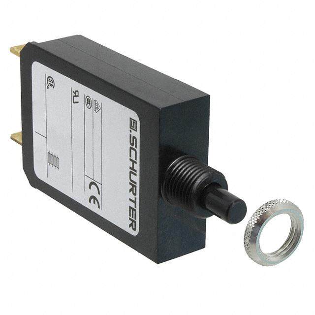
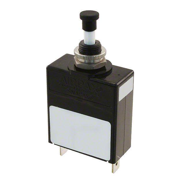
- 型号: 104-PR-0.5A
- 制造商: E.T.A. CIRCUIT BREAKERS
- 库位|库存: xxxx|xxxx
- 要求:
| 数量阶梯 | 香港交货 | 国内含税 |
| +xxxx | $xxxx | ¥xxxx |
查看当月历史价格
查看今年历史价格
104-PR-0.5A产品简介:
ICGOO电子元器件商城为您提供104-PR-0.5A由E.T.A. CIRCUIT BREAKERS设计生产,在icgoo商城现货销售,并且可以通过原厂、代理商等渠道进行代购。 104-PR-0.5A价格参考。E.T.A. CIRCUIT BREAKERS104-PR-0.5A封装/规格:断路器, Circuit Breaker Thermal 500mA 250V AC 48V DC Push to Reset Through Hole。您可以下载104-PR-0.5A参考资料、Datasheet数据手册功能说明书,资料中有104-PR-0.5A 详细功能的应用电路图电压和使用方法及教程。
| 参数 | 数值 |
| 产品目录 | |
| 描述 | CIR BRKR THRM 500MA 250VAC 48VDC |
| 产品分类 | |
| 品牌 | E-T-A |
| 数据手册 | |
| 产品图片 |
|
| 产品型号 | 104-PR-0.5A |
| rohs | 无铅 / 符合限制有害物质指令(RoHS)规范要求 |
| 产品系列 | 104 |
| 产品培训模块 | http://www.digikey.cn/PTM/IndividualPTM.page?site=cn&lang=zhs&ptm=24709 |
| 产品目录绘图 |
|
| 产品目录页面 | |
| 其它名称 | 104-PR-0.5AMP |
| 安装类型 | PCB |
| 断路器类型 | 热敏式 |
| 极数 | 1 |
| 标准包装 | 10 |
| 照明 | - |
| 照明电压(标称值) | - |
| 致动器类型 | 按下复位 |
| 额定电压-AC | 250V |
| 额定电压-DC | 48V |
| 额定电流 | 500mA |


- 商务部:美国ITC正式对集成电路等产品启动337调查
- 曝三星4nm工艺存在良率问题 高通将骁龙8 Gen1或转产台积电
- 太阳诱电将投资9.5亿元在常州建新厂生产MLCC 预计2023年完工
- 英特尔发布欧洲新工厂建设计划 深化IDM 2.0 战略
- 台积电先进制程称霸业界 有大客户加持明年业绩稳了
- 达到5530亿美元!SIA预计今年全球半导体销售额将创下新高
- 英特尔拟将自动驾驶子公司Mobileye上市 估值或超500亿美元
- 三星加码芯片和SET,合并消费电子和移动部门,撤换高东真等 CEO
- 三星电子宣布重大人事变动 还合并消费电子和移动部门
- 海关总署:前11个月进口集成电路产品价值2.52万亿元 增长14.8%


PDF Datasheet 数据手册内容提取
Thermal Overcurrent Circuit Breakers 104/105/106-... Description Miniaturised single pole thermal circuit breaker with push-to-reset, tease-free, trip-free, snap action mechanism (R-type TO CBE to EN 60934). Available in versions for PCB or panel mounting, snap-in or threadneck, or as an integral type. Approved to CBE standard EN 60934 (IEC 60934). For higher current ratings see type 1140. Typical applications Motors, transformers, solenoids, printed circuit boards, hand-held machines and appliances, marine applications, caravans. 1 Ordering information 104-... 105-... 106-... Type No. 104 PCB mounting type (-PR), or integral type (-P30/P10) Technical data 105 snap-in panel mounting 106 t hreadneck panel mounting with metal hex and plastic knurled nut For further details please see: www.e-t-a.de/ti_e (hardware bulk shipped with 5 pcs plus) 106-M2 threadneck panel mounting 3/8-27UNS with collar, metal hex nut Voltage rating AC 240 V; DC 48 V and plastic knurled nut (hardware bulk shipped with 5 pcs plus) (UL: AC 250 V; DC 48 V) Terminal design Current ratings 0.05...10 A P10 blade terminals A6.3-0.8 (QC .250) Typical life 0.05...5 A 1,000 operations at 2 x I , inductive P30 blade terminals A2.8-0.8 (QC .110) N DC 28 V: 3,000 operations at 2 x I , inductive PR solder terminal pins for PCB mounting (type 104 only) N 6...8 A 500 operations at 2 x I , inductive N PR3 PCB mounting (vertical), type 104 only 10 A 50 operations at 2 x I , inductive N Current ratings Ambient temperature -20...+60 °C (-4...+140 °F) T 60 0.05...10 A Insulation co-ordination rated impulse pollution 106 - P30 - 5 A ordering example (IEC 60664 and 60664 A) withstand voltage degree 2.5 kV 2 Please be informed that we have minimum ordering quantities to be observed. reinforced insulation in operating area Dielectric strength test voltage (IEC 60664 and 60664A) Preferred types operating area AC 3,000 V Insulation resistance > 100 MΩ (DC 500 V) Preferred types Standard current ratings (A) Interrupting capacity Icn 0.05...8 A 6 x IN AC 0.05...10 A 6 x I DC 0.5 0.8 1 1.2 1.5 2 3 4 5 6 8 10 N Interrupting capacity I U 106-P10- x x x x x x x x x x x x (UL 1077) 0N.05...10 A ACN 250 V 2,000 A 106-P30- x x x x x x x x x x x x 0.05...10 A DC 48 V 200 A Degree of protection operating area IP40 (IEC 60529/DIN 40050) terminal area IP00 Standard current ratings and typical internal resistance values Vibration 10 g (57-500 Hz) ± 0.76 mm (10-57 Hz), to IEC 60068-2-6, test Fc, 10 frequency cycles/axis Current Internal Current Internal rating (A) resistance (Ω) rating (A) resistance (Ω) Shock 25 g (11 ms) to IEC 60068-2-27, test Ea Corrosion 96 hours at 5 % salt mist, 0.05 285 1.8 0.28 to IEC 60068-2-11, test Ka 0.08 134 2 0.25 Humidity 240 hours at 95 % RH, to IEC 60068-2-78, test Cab 0.1 81 2.5 0.18 Mass approx. 10 g 0.2 22 3 0.11 0.3 8.7 3.5 0.076 Approvals 0.4 5.5 4 0.067 0.5 3.3 4.5 0.051 Authority Standard Rated voltage Current ratings 0.6 2.45 5 ≤ 0.05 VDE EN 60934 AC 240 V 0.02 A… 8 A DC 48 V 0.02 A…10 A 0.7 1.6 6 ≤ 0.05 UL UL1077 AC 250 V 0.05 A…10 A 0.8 1.45 7 ≤ 0.05 DC 48 V 0.05 A…10 A 1 0.9 8 ≤ 0.05 CSA C22.2 No 235 AC 250 V 0.05 A…10 A DC 48 V 0.05 A…10 A 1.2 0.6 10 ≤ 0.05 CQC GB 17701 AC 240 V 0.05 A…8 A 1.5 0.4 DC 48 V 0.05 A…10 A 1816 www.e-t-a.de 1
Thermal Overcurrent Circuit Breakers 104/105/106-... Dimensions 104-PR 104-P30 ø7 OFF ON .ø1457 OFF ON .276 .1ø547 9.5.374 9.5374 . 1 max. 3max .118 1.26.5.047.256 27.61.09 29.61.16 max. 3max .118 1.26.5.256.047 27.61.0929.61.16 3.5138 PCB mounting holes 9.5.374 . 104-PR 104-PR hole for mounting blade terminals 104-PR-A3 7...10 A screw M2 usable depth DIN 46244-A2.8-0.8 0.05...06. 5A 0.5 4.5 mm (.177 in.) 6.5 (QC .110) cut-out dimensions terminal design for .020 .020 .256 6.5 .013c9orrect stand-off d.i0110s.3t8a1.433n4.5ces.177 301.18 1 3 ø1.52.059 301.181 2 ø1.5.059 .3954 .71498 11.433 Ø 2.2.087 .256 7.3.287 9.1 .358 1.678.59 .3185±±0..0208 9.5 ø1.5 9.5 170..4.1-0P 3A0 19.2 .374 .059 .374 .756 21 17.5 8±0.2 .827 .689 .315±.008 104-PR3 0.05...6 A 105-P30 ø7 9.5 OFF374 ON .276 .1ø547 9.5OFF.374 ON ..11ø55477 2.079 .2ø776 . 56 6.5.256 1.2.04727.61.0929.61.17 6.2244 max. 3max. 118 6.1.2.25.047 27.61.0929.61.16 10.00.3943.81 15.4 .1457 max. 3max .118 .014.27 0.9 . .71498 9.5.374bD(QlIaNCd e4.1 6t1e20r4m)4-inAa2ls.8-0.8 .41313 .606 .014.27 .035 14.551 panel caut-out 12 .472 PCB mounting holes 25 hole for mounting screw M2x5 0.05...6 A .984 b 6.5 7.7 .256 .303 2.1.083 d a b 11433 mm inch mm inch .395.18 19.2 . 0.9.035 .1650.64 2011-...8053 .07...9000-335.199118 22221222...912 ....888866772604 .1414.53 ++0.0.312 d .756 105-P3 7...10 A 07...10 A 7 5.4 415 .213 7...10 A . 0.9035 7.7 . 5.4 4 .303 .213 .157 This is a metric design and millimeter dimensions take precedence ( mm ) inch 2 www.e-t-a.de 1816
Thermal Overcurrent Circuit Breakers 104/105/106-... Thermal Overcurrent Circuit Breakers 104/105/106-... Dimensions Installation drawings 106-P30 104-… operating area 3/8-27UNS-2A tightening torque max. 0.8 Nm FF N ø4 O O .157 13.5.531 10.5.413 7.276 max. 3max .118 1.2.047 0.7.02827.61.09 8.315 8.315 1 9.5.374 .3815 mounting area .3815 19 .748 11 blade terminals .433 105-… operating area 15.7 DIN 46244-A2.8-0.8 .618 (QC .110) S.5W5114 mounting hole 8.9 - 0.1.350 - .004 8.8346 . 9 9.6- 0.1 .354 .378 - .004 106-P30 7...10 A 8.315 8.315 8 8 .315 mounting area .315 106-… operating area 106-M2 3/8-27UNS-2A tightening torque max. 0.8 Nm mounting hole 8.9 - 0.1350 - .004 . 9.6 - 0.1 .378 - .004 8.315 8.315 8 mounting area 8 Terminal design .315 .315 104/105/106-P10 Internal connection diagrams 0.05...6 A 7...10 A blade terminals 10.394 D(QINC 4 .6225404)-A6.3-0.8 Types110045 6.3 106 .248 polarizing tooth 1 2 This is a metric design and millimeter dimensions take precedence ( mm ) inch 1816 www.e-t-a.de 3
Thermal Overcurrent Circuit Breakers 104/105/106-... Typical time/current characteristics at +23 °C/+73.4 °F Accessories 10000 0.05 - 6 A Water splash cover (transparent)/knurled nut assembly (type 106-... only) 7 - 10 A X 201 285 01 (IP64) 1000 ds n o c n se 100 1 e i m p ti Tri Knurled nut 3/8", plastic (standard) 10 Y 307 117 02 ø15 3 .591 .118 1 0.1 3/8-27UNS-2B 1 2 4 6 810 20 30 … times rated current The time/current characteristic curve depends on the ambient temperature prevailing. In order to eliminate nuisance tripping, please multiply the Hex nut 3/8", nickel-plated brass circuit breaker current ratings by the derating factor shown below. See also Y 300 192 01 section Technical information. Ambient temperature °F -4 +14 +32 +73.4 +104 +122 +140 3/8-27UNS-2B 2.5 °C -20 -10 0 +23 +40 +50 +60 .098 Derating factor 0.76 0.84 0.92 1 1.08 1.16 1.24 SW14 .551 This is a metric design and millimeter dimensions take precedence ( mm ) inch All dimensions without tolerances are for reference only. In the interest of improved design, performance and cost effectiveness the right to make changes in these specifications without notice is reserved.Product markings may not be exactly as the ordering codes. Errors and omissions excepted. 4 www.e-t-a.de 1816

 Datasheet下载


