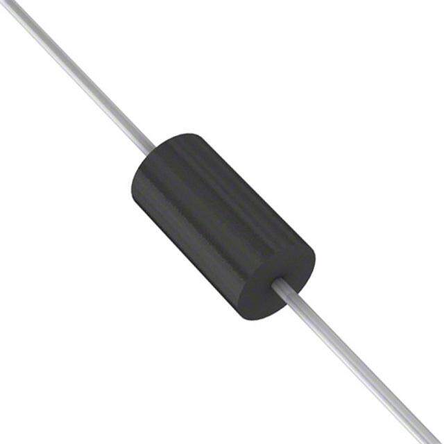
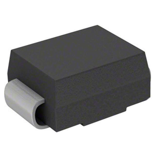
- 型号: 1.5SMC150CA
- 制造商: Littelfuse
- 库位|库存: xxxx|xxxx
- 要求:
| 数量阶梯 | 香港交货 | 国内含税 |
| +xxxx | $xxxx | ¥xxxx |
查看当月历史价格
查看今年历史价格
1.5SMC150CA产品简介:
ICGOO电子元器件商城为您提供1.5SMC150CA由Littelfuse设计生产,在icgoo商城现货销售,并且可以通过原厂、代理商等渠道进行代购。 1.5SMC150CA价格参考。Littelfuse1.5SMC150CA封装/规格:TVS - 二极管, 。您可以下载1.5SMC150CA参考资料、Datasheet数据手册功能说明书,资料中有1.5SMC150CA 详细功能的应用电路图电压和使用方法及教程。
| 参数 | 数值 |
| 品牌 | Littelfuse |
| 产品目录 | 半导体 |
| 描述 | TVS 二极管 - 瞬态电压抑制器 1.5SMC150CA |
| 产品分类 | 分离式半导体 |
| 产品手册 | |
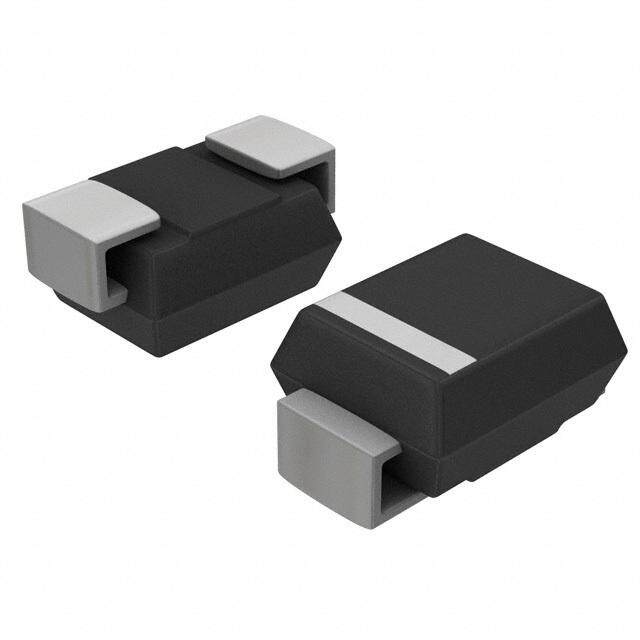
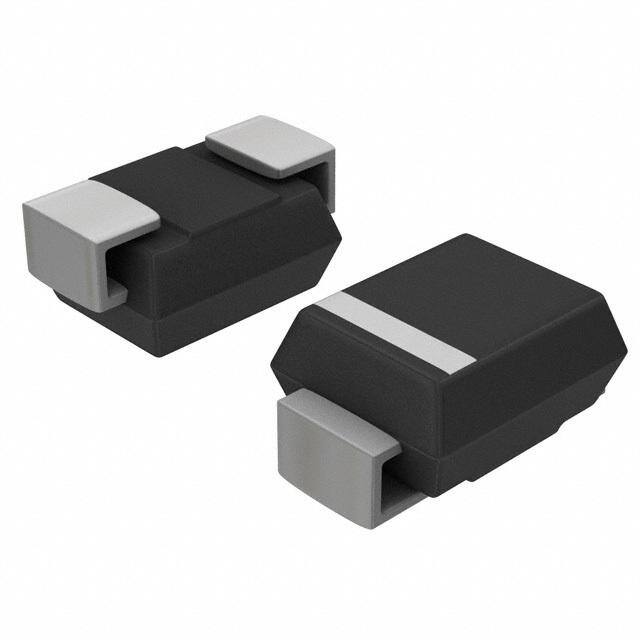
| 产品图片 |
|
| rohs | 符合RoHS |
| 产品系列 | 二极管与整流器,TVS二极管,TVS 二极管 - 瞬态电压抑制器,Littelfuse 1.5SMC150CA |
| 产品型号 | 1.5SMC150CA |
| 产品种类 | TVS 二极管 - 瞬态电压抑制器 |
| 击穿电压 | 143 V |
| 单位重量 | 210 mg |
| 商标 | Littelfuse |
| 安装风格 | SMD/SMT |
| 封装 | Reel |
| 封装/箱体 | DO-214AB |
| 尺寸 | 6.22 mm W x 7.11 mm L x 2.62 mm H |
| 峰值浪涌电流 | 7.3 A |
| 峰值脉冲功率耗散 | 1.5 kW |
| 工作电压 | 128 V |
| 工厂包装数量 | 3000 |
| 最大工作温度 | + 150 C |
| 最小工作温度 | - 65 C |
| 极性 | Bidirectional |
| 端接类型 | SMD/SMT |
| 系列 | 1.5SMC |
| 钳位电压 | 207 V |





- 商务部:美国ITC正式对集成电路等产品启动337调查
- 曝三星4nm工艺存在良率问题 高通将骁龙8 Gen1或转产台积电
- 太阳诱电将投资9.5亿元在常州建新厂生产MLCC 预计2023年完工
- 英特尔发布欧洲新工厂建设计划 深化IDM 2.0 战略
- 台积电先进制程称霸业界 有大客户加持明年业绩稳了
- 达到5530亿美元!SIA预计今年全球半导体销售额将创下新高
- 英特尔拟将自动驾驶子公司Mobileye上市 估值或超500亿美元
- 三星加码芯片和SET,合并消费电子和移动部门,撤换高东真等 CEO
- 三星电子宣布重大人事变动 还合并消费电子和移动部门
- 海关总署:前11个月进口集成电路产品价值2.52万亿元 增长14.8%


PDF Datasheet 数据手册内容提取
Features Applications NT *RoHS CHOAML&POLIGEAN FREE nnn RSBuroerHafaSkcd eco owMmnop uVlinaotnl tSta*Mg eaC:n 6dp. a8hc atklooa gg5ee5n0 fvreoelt*s* nnn IIIEEECCC 666111000000000---444---245 EESSFuTDrg e(Min. Level 4) ** n Peak Pulse Power: 1500 watts n Typical temperature coefficient: ∆VBR = 0.1 % x VBR @ 25 °C x ∆T NT MPLIA HS CO 1.5SMC Transient Voltage Suppressor Diode Series Ro * General Information The markets of portable communications, computing and video equipment are challenging the semiconductor industry to develop increasingly smaller electronic components. D FREE LEA Bourns offers Transient Voltage Suppressor Diodes for surge and ESD protection applications, in compact chip package DO-214AB (SMC) size format. The Transient Voltage Suppressor series offers a choice of Breakdown Voltages from 6.8 V up to 550 V. Typical fast response times are less than 1.0 picosecond for unidirectional devices and less than 5.0 picoseconds for bidirectional devices from 0 V to Minimum Breakdown Voltage. BmoiEnuilrmencisz®ter Csic hraoipll l C Dahwioaadryea.s c cteornifsotrimcs t o( @JE TDAE C= s2t5a n°dCa Urdns,l easres eOatshye trow hisaned LNVElREeAoRoD H SwISFt OeRCiNEtOdSEh MA)P RsLIE tAaNTn*dard pick and place equipment and their flat configuration Parameter Symbol Value Unit Minimum Peak Pulse Power Dissipation (TP = 1 ms) (Note 1,2) PPK 1500 Watts Peak Forward Surge Current 8.3 ms Single Half Sine Wave Superimposed on Rated Load IFSM 200 Amps (JEDEC Method) (Note 3) M(Faoxr imUnuimdi rIencsttiaonntaal nUenoiutss OFnolryw)ard Voltage @ IPP = 100 A 11..55SSMMCC62.280AA ~ ~ 11..55SSMMCC250500AA VF 35..50 Volts Operating Temperature Range TJ -55 to +150 °C Storage Temperature Range TSTG -55 to +150 °C 1. Non-repetitive current pulse, per Pulse Waveform graph and derated above TA = 25 °C per Pulse Derating Curve. 2. Thermal Resistance Junction to Lead. 3. 8.3 ms Single Half-Sine Wave duty cycle = 4 pulses maximum per minute (unidirectional units only). How to Order 1.5SMC 6.8 CA - H Series Asia-Pacific: 1.5SMC = SMC/DO-214AB Tel: +886-2 2562-4117 Breakdown Voltage Email: asiacus@bourns.com 6.8 to 550 = 6.8 to 550 VBD Suffix Europe: A = 5 % Tolerance Unidirectional Device Tel: +36 88 520 390 CA = 5 % Tolerance Bidirectional Device Email: eurocus@bourns.com Reel The Americas: (blank) = 13 inch reel -H = 7 inch reel Tel: +1-951 781-5500 Email: americus@bourns.com www.bourns.com * RoHS Directive 2002/95/EC Jan. 27, 2003 including annex and RoHS Recast 2011/65/EU June 8, 2011. **Bourns considers a product to be “halogen free” if (a) the Bromine (Br) content is 900 ppm or less; (b) the Chlorine (Cl) content is 900 ppm or less; and (c) the total Bromine (Br) and Chlorine (Cl) content is 1500 ppm or less. Specifications are subject to change without notice. The device characteristics and parameters in this data sheet can and do vary in different applications and actual device performance may vary over time. Users should verify actual device performance in their specific applications.
1.5SMC Transient Voltage Suppressor Diode Series Electrical Characteristics (@ TA = 25 °C Unless Otherwise Noted) Maximum Maximum Maximum Working Peak Breakdown Voltage Reverse Reverse Reverse Unidirectional Device Bidirectional Device Reverse VBR (Volts) Voltage Leakage Voltage Surge @ VRWM @ IRSM Current Part No. Marking Part No. Marking Min. Max. @ IT (mA) VRWM (V) IR (μA) VRSM (V) IRSM (A) 1.5SMC6.8A 6V8A 1.5SMC6.8CA 6V8C 6.45 7.14 10 5.8 1000 10.5 144.8 1.5SMC7.5A 7V5A 1.5SMC7.5CA 7V5C 7.13 7.88 10 6.4 500 11.3 134.5 1.5SMC8.2A 8V2A 1.5SMC8.2CA 8V2C 7.79 8.61 10 7.02 200 12.1 125.6 1.5SMC9.1A 9V1A 1.5SMC9.1CA 9V1C 8.65 9.5 1 7.78 50 13.4 113.4 1.5SMC10A 10A 1.5SMC10CA 10C 9.5 10.5 1 8.55 10 14.5 104.8 1.5SMC11A 11A 1.5SMC11CA 11C 10.5 11.6 1 9.4 5 15.6 97.4 1.5SMC12A 12A 1.5SMC12CA 12C 11.4 12.6 1 10.2 5 16.7 91 1.5SMC13A 13A 1.5SMC13CA 13C 12.4 13.7 1 11.1 1 18.2 83.5 1.5SMC15A 15A 1.5SMC15CA 15C 14.3 15.8 1 12.8 1 21.2 71.7 1.5SMC16A 16A 1.5SMC16CA 16C 15.2 16.8 1 13.6 1 22.5 67.6 1.5SMC18A 18A 1.5SMC18CA 18C 17.1 18.9 1 15.3 1 25.2 60.3 1.5SMC20A 20A 1.5SMC20CA 20C 19 21 1 17.1 1 27.7 54.9 1.5SMC22A 22A 1.5SMC22CA 22C 20.9 23.1 1 18.8 1 30.6 49.7 1.5SMC24A 24A 1.5SMC24CA 24C 22.8 25.2 1 20.5 1 33.2 45.8 1.5SMC27A 27A 1.5SMC27CA 27C 25.7 28.4 1 23.1 1 37.5 40.5 1.5SMC30A 30A 1.5SMC30CA 30C 28.5 31.5 1 25.6 1 41.4 36.7 1.5SMC33A 33A 1.5SMC33CA 33C 31.4 34.7 1 28.2 1 45.7 33.3 1.5SMC36A 36A 1.5SMC36CA 36C 34.2 37.8 1 30.8 1 49.9 30.5 1.5SMC39A 39A 1.5SMC39CA 39C 37.1 41 1 33.3 1 53.9 28.2 1.5SMC43A 43A 1.5SMC43CA 43C 40.9 45.2 1 36.8 1 59.3 25.6 1.5SMC47A 47A 1.5SMC47CA 47C 44.7 49.4 1 40.2 1 64.8 23.5 1.5SMC51A 51A 1.5SMC51CA 51C 48.5 53.6 1 43.6 1 70.1 21.7 1.5SMC56A 56A 1.5SMC56CA 56C 53.2 58.8 1 47.8 1 77 19.7 1.5SMC62A 62A 1.5SMC62CA 62C 58.9 65.1 1 53 1 85 17.9 1.5SMC68A 68A 1.5SMC68CA 68C 64.6 71.4 1 58.1 1 92 16.5 1.5SMC75A 75A 1.5SMC75CA 75C 71.3 78.8 1 64.1 1 103 14.8 1.5SMC82A 82A 1.5SMC82CA 82C 77.9 86.1 1 70.1 1 113 13.5 1.5SMC91A 91A 1.5SMC91CA 91C 86.5 95.5 1 77.8 1 125 12.2 1.5SMC100A 100A 1.5SMC100CA 100C 95 105 1 85.5 1 137 11.1 1.5SMC110A 110A 1.5SMC110CA 110C 105 116 1 94 1 152 10 1.5SMC120A 120A 1.5SMC120CA 120C 114 126 1 102 1 165 9.2 1.5SMC130A 130A 1.5SMC130CA 130C 124 137 1 111 1 179 8.5 1.5SMC150A 150A 1.5SMC150CA 150C 143 158 1 128 1 207 7.3 1.5SMC160A 160A 1.5SMC160CA 160C 152 168 1 136 1 219 6.9 1.5SMC170A 170A 1.5SMC170CA 170C 162 179 1 145 1 234 6.5 1.5SMC180A 180A 1.5SMC180CA 180C 171 189 1 154 1 246 6.2 1.5SMC200A 200A 1.5SMC200CA 200C 190 210 1 171 1 274 5.5 1.5SMC220A 220A 1.5SMC220CA 220C 209 231 1 185 1 328 4.6 1.5SMC250A 250A 1.5SMC250CA 250C 237 263 1 214 1 344 4.4 1.5SMC300A 300A 1.5SMC300CA 300C 285 315 1 256 1 414 3.7 1.5SMC350A 350A 1.5SMC350CA 350C 332 368 1 300 1 482 3.2 1.5SMC400A 400A 1.5SMC400CA 400C 380 420 1 342 1 548 2.8 1.5SMC440A 440A 1.5SMC440CA 440C 418 462 1 376 1 602 2.5 1.5SMC480A 480A 1.5SMC480CA 480C 456 504 1 408 1 658 2.3 1.5SMC510A 510A 1.5SMC510CA 510C 485 535 1 434 1 698 2.1 1.5SMC530A 530A 1.5SMC530CA 530C 503.5 556.5 1 477 1 725 2.1 1.5SMC540A 540A 1.5SMC540CA 540C 513 567 1 486 1 740 2 1.5SMC550A 550A 1.5SMC550CA 550C 522.5 577.5 1 495 1 760 2 Notes: 1. Suffix ‘A’ denotes a 5 % tolerance unidirectional device. 3. For bidirectional devices with a VR of 10 volts or less, the IR limit is double. 2. Suffix ‘CA’ denotes a 5 % tolerance bidirectional device. Specifications are subject to change without notice. The device characteristics and parameters in this data sheet can and do vary in different applications and actual device performance may vary over time. Users should verify actual device performance in their specific applications.
31.351S2M -C 2 T mramns SieMntD V Tolrtiamgme Sinugp pProetsesnotri oDmioedtee rSeries Rating 1&00 Chara1c0t0eristic Curves 200 200 STUhpseeePPP rcdsiuuufie svclllPeak Pulse Derating in Percent ofhsssiacotPeak Pulse Derating in Percent ofeeeeiI, Peak Pulse Current (%)Peak Pulse Derating in Percent ofuPeak Power or CurrentoP, Peak Power (KW)P PclndDWRI, Peak Pulse Current (%)Peak Power or CurrenthP, Peak Power (KW)I, Peak Pulse Current (%)PsPeak Power or Current P, Peak Power (KW)PPav752 P1ea1aar1e150500511a0rrt752r0.10v000e7521000c01iia150500105f 10n150500t005yes.1000e0001t00.00 000u00Peak Pulse Derating in Percent of0g.rifa001i0nb0o1cs 0 1Peak Pulse Derating in Percent ofx.Tjµ0tI, Peak Pulse Current (%)tPeak Pulse Derating in Percent ofC1Peak Power or Current.eg0r P, Peak Power (KW)uPi1As 1cP cxm Taµ 2I, Peak Pulse Current (%)= xPeak Power or Currentus0TtµI, Peak Pulse Current (%) P, Peak Power (KW)PTPeak Power or CurrentAlsC5 P, Peak Power (KW)P12 P T 0Ast752P1Pa12dr=o051R201=T150500nu055ve12P1TT100 5 7520=2.P1T°00cd000752vW051001.R0Pe0re150501C0b15005Rh0i15050 P10010 a05 c1v=.p0P1°0 y0 a0000W 1a.005=.00kµe°000eW00Cb100 .va. en00e1C 0b1a0Rs1Hµ 0 y0eva0ra1A5pg kµ.0 y0a 1sa.5 faxav0k.T µµ01E 0mRes. o1veHµ 0ml le1v 01RsAsHAµ fu.1.rev rsA. faxa0 TA. µbw2fs=Em.mxfTeaoav00µel loEmToAsi.5 fu12. llaT7Arts0ie1fu1 A(.r Pb2tre=mSelTv05 Aa2R5nbI0=mhmTu00evi.5rNR2 TPaTP7s10 he5ti. 21o(=T s Pea07°e WSlT51 Pµa(a. Ro5n,SeI0oTu05S=C lTb1DRu0a0 5nNIRPPus10s hinanPt wNMRP=e 1e Psn° y0aht t We= µ5.o °eTk,Sµeoc-IWuT m=Cb1D.0 µ1 e vo,S nofRTnCb1r1s0)= 0DanRPs, HewµtMlei2a y0esva0e nPs ewAMnh5eT ky0o.µap2S-I Tusime5.1k fµaa.vT0p ne0f-IiRnur1mE)e 0mviR1s0, oHeµtnlnifiMR12 0rllevRs)s0 e Hµ,es Aminl difue2v.p.2WSr0Tre Asisc .n Pf.aa.0 pApe20tbSsTn.aiEmefmaadt00e1o.vedpe0iiMenETmlleeo i0hueemtiw.iti dMlflu. eWars07 reeadm.iPfuu d.A1 A( rtWbrlea1vmd(PS e1cAalT v0ba5stnihtItmTaeerdu1v0idu1m tiw.itieiNhR0aT aseeas0P7s ieuhPie.ed=rttiewtiu A 1a(7 ee2s0µele1 vdi (Sy u1 ca l(T A 0 µa o5sn h,SItlorP 1vsuSTrlTu1ds0(xdca=a Ds5fmn0 Ws5I (sehNhtR02sasu0ePr1s sedhPe=mnP itNeRe)whM0°l Phuase se2eµhep en Pte=e y e5s 1 eµ o 2T,SµeCorP -Is uuTtdxya m t =µfDoflW1s,S5e (o ener2Ps TfseRue=od rDxss)0hi fnPiWs,5()wM°l2)l svueiee2s°nenPn0ed iwc Ms) e5s e1°nl eu TeCp0e2Sn-ITute eiwaCmtf5s l1T1.5tep-nCeIe0iu feRnmto r ast1)0h1efil 0,ne0 fifelRf)aviieM3r2°)Won s10hd,0i pe0d esl imcin)o2v ed °5p0e0n2eW SrTsd ds eiwCn cP.e.5p2 e.pS0ee T0te inawea wC1er.d0 01p50e0e00eb fn%aiai M3t eWT e110d p0 eiuaem0iimttwMnfitoa d3ahW5 eW1rs0d pe0dsm vadyi idhP.ou A.Wr5 kmte lwds a1vPrd p0(.1ca 0 0t.0b e %saveih attw Tdea1rra10i( duoa0m0m ittbw itR%aeTht0heGaseis0 upc feveatPamwsedy=itTtiehu tAhes0nkm2 µelfdov1 aivyu hA(y ca 0u. efklsmv h lr1tvr P Psua(car1 dx( 10dop fsEm hdWs5et(Riove hIr0G2s rasa1aedc f( eme oPrse=eicTehR0)tasP°Gl um2e )eµ7Pefoce=foen .es rT ry p t5s 1u2.µ fe r Cfr aPA o Psuy d tdxa1tpfm flEeu WsS.5f(o5riP rIres 2usaPdexeho f1sp0Whsr5i(Einto)2sIrP°)el vu.amoe)n7°onin.rd)r rMp° i5l s uP1eem )n7Co0eA .t 1rt5s eorwaC1ptfmleS5Ct5 ieeAt e athfo ls10hmie nSve5i00ef)av.o3 sn.°0hhWnin1dp0dnM )vioe°.n n50edta1 ds e MwCe .5t0ee.s e te 1wCmw 1r520 e40t00r b0 f%aa3 t1.W 1dp0.0amfait03oWyh.15dp00 .ids v ayohs.5. kme 0ds mw .r2 0.4 0 0 e 0b e%avw tm r0ai200( 4oabm %attRhGn0 a.mcfvetasyThsht km00v.afyohs kmu0.ef v 0r Pa ( 1opevE 0dRo IrGaa( ocfersRTGtPcmf)e7fosoT.rtirp u.ffor A Pf 1up.mfEeSro5 iIrPa1phfEronIrPa.m)n7roe.rrMPpm)7o.Ar t1rpmeSrt5iA Junction Capacitance (pF) ChmeS5in0 -e.hJn.nM.nt1M ntt1 mJunction Capacitance (pF) CI- Peak Forward Surge Current (A)2t40 -JJunction Capacitance (pF) CFSM.RM(AV) Steady State Power Dissipation (W)t0 -.J0 . sa0 mI- Peak Forward Surge Current (A)1240mFSMRM(AV) Steady State Power Dissipation (W)2I- Peak Forward Surge Current (A)4pFSMRM(AV) Steady State Power Dissipation (W)100.s0.0sp110000111111010l10005i1024680246834210c10010000.1111121000000000000.....0a100011111200010050000024680246801000342105t10000246802468034210.1000000i000000100001.....0Junction Capacitance (pF) C.0000o100000000000000000 -.....0J000100 00000n TfV10MTS1 Junction Capacitance (pF) C 1I- Peak Forward Surge Current (A)01 -Junction Capacitance (pF) CsJ sJFSMRM(AV) Steady State Power Dissipation (W)= - Jyi TfV t g =a TfV I- Peak Forward Surge Current (A)a1es1J FSMRM(AV) Steady State Power Dissipation (W)= I- Peak Forward Surge Current (A) p sJFSM RM(AV) Steady State Power Dissipation (W) n=10 i =. x 2g =i a 0 1 100dig1 = 1 11111 51i 10c 5U1000= .d5M 10 2 2468m 024682=0a34210. 100 0210000n°0 .100 a111112 500000000005c H..... 50111112y U C1000 5i0001005M 00000 100024685 U 024680d2m342105tM 02468l zu024680 10000n° 234210.u1 0 1000000i0000 000000n5°1 H......0C 0 r 0000i 000000000100V5S.....000000H dJmCa 000 100 iem 00000z dm p TfV10i zl c 1 1 r0 u itV -1 VNsJ =rt ed V pa pi e i TfVB ocu gp n eTfV = N- cV N s1J 5 = Rtnt -m sJv V Np= i t i = .B 0cp eoau2gii 6= i 0Bo ogu = 15 c b Rn l 5m-1 0 5 t R 5nU I=m B.e 0 1eM @ a 2nT=6 2.n P0 i 0 R2 a0 n°6 b0 r i H0 l 5o-L 05 d d bp H 5lU C5 I ei B-- 01eM @ 5 UT oo d2mInzV,B Mi1ue R @ e0vz 2 n°TRnrr niH0 0 R n°i Lf5RddHLriH0eec C r erRi 5VL wHdd C 7 od miezV e ,fiCu cret v z dm o pezrV ,ioe u z i si v5fRc CLr taeec rvyiR Vf- RVNsLiee7 erec r t RVep C dcoretcpe 7 e pi miCe Bcreti s5 o c pu a tsnalB evyr i sc5 - VN s5ieteaeTLR vtyn - VmNtdo acspeie1tr a i ips iBdpo0ceeoo aiu e 6snlDlBvB i t0onu 5esn bTLlB Rmnla a mt - 5Vaae0ie 1Rr anTL 1mI c s tBia01e1eo@ arkdet T6 tl n ve s0i 0aReo 6 epe 0 o= bl vriH0ml0Bcadia -Va Le0 b d6d lm 1aIae- 0B e0V a ver1er @ kdoIT io1t Bn zmV ,1 ei@ 0uR ikdTvdp00nr o=t r r iH0aBRwd Lpf 0Rrd6t od=ei H0 Lae ec B dieRL e0 dd r 6 o raH7 eio zVVa, e0i C0nut r t cretdvoo 0 irezV,r iu we0 uvy i sd5f0Rrr Lzi a tae ec w ivyR f cSURn L V eseci a erH7 Rrin V Cnt dcore t7 c e rtHev VneCio cretent u 1i s5i ez tsnea lcB uivy su5 ocaU 1 igtlVaszi e e vyTLr 0 c Udt(tsdoiaeVc e 1tn r rr neadioo2s cie1e° i 0teo re iisnne llvyBo o01a ir1 i glsn elCB 5TL0mo a adt(gCt1 iVaeaeel TL1nlr0 1tead2t as(i1 °or0eon)kde istlc iav20@aeo°0er gp il0vC o5= e0mB aadva (r tuVaege C65lma a1 e V Vaeie0e r)lkdo e1 i tco e @ 0kd) d p 0t0 V )r o= c r@Bwdr p(t0 n C o= 6 Bad i V R (iet 0 6r vorH i oea V0V i r0ntt o1d i0V )re o 0 wudi0nrl uV ) z aw eim5 R c Un aV rHir VaV R nt r1H teV0a nent ro u11eli ze u5 ocU=l1 zi lV rr0cVU5 dt (.V rtn0Vne ao2 1 te°i 00neio 1 0oai= r1 igl C 5 0o 1 d=ti(le 0 nl n dt(ea2 n° 0)V ia2c °0 @a 0 ri gC5 a 0 r1g (tteC5 l e Vei l )V e 7 co @ ) V cV )@ 1 1 1 (tn 5 (1 tVRi 0 0V 7 oia 1 oV )7 101 V n0)l 5 115n R 5 00RVa 0 10a00 100l 05 l0= 5 V0 2V00 0 0 0= = 2 0 2V 0 0 0 01 0 V 07 V 1115 1 007 71 010511500000000002002020000 Peak Forward Surge Current (Amps)P- Peak Pulse Power (kW)PPMPeak Forward Surge Current (Amps)Peak Forward Surge Current (Amps)P- Peak Pulse Power (kW)12PPMP- Peak Pulse Power (kW)PPM00111210000120001110000111.1000010100001000 11.00µ11.1s µ Peak Forward Surge Current (Amps)0CµP- Peak Pulse Power (kW)s.PPMCos3Peak Forward Surge Current (Amps)0CpPeak Forward Surge Current (Amps)o0CS1P- Peak Pulse Power (kW)212.PPMCoP- Peak Pulse Power (kW)ppPPM3.Coi P00131pnoxepS12po12u(S1000012 pgrp12e0i PJ0p1p0011l 10nxi0 Pelp001rs1P1E.nxe3eu (p10000 g1rµeue1(00000J0D Pa1 gr11l 0e00J0l H1 r1sPs0l 1E.0de3µ laW rsE1P. 1Ee3µe ”a1DPa 1sdµeC DHPa A1sld iµH(aW 0CE sfdµd ”aW AEra8 sMd”.CCaoS etAts dl3C.ir( dAh0C fld0pa io0C(ieAr 8eS5f 12dM n .ArCo8S sett p-Mpa.t83Co.rSi PextNdhte3 h0p.anroxiesedhepS5.P12p0 ao n- iSue(1e5123suo p-g8r pant8 eWi PspJxN0u p1-ea th8l 0in P mxdesxN.lpers.P PhnEx mee3-l0spu (13uo.P g8r )su(a-µee1W3 uJog0rµuDPa1 8b1 el 0J Wmd01e.luHvs rl smPsE0m mddle3sl0 .rsaeW PEE )e3ms eaµl0e” aµDP a Wb )1sµe rdaCDPma eµHv1s Abms l dsHie (vaeW ssE mfdo des aW ”EeAra8 1iW erMd)”aCmdS f etWAtdNwTrlC .imr0 A( dh lfo id0ta (Ci AefAr8e5 1idoo aM )hnA r8 dSfs1iettMNwT -)at8y. Sdr0etnvtf xNdhNwT e1 .h=0rta0dChi Ase(e5c.oP0aea t h-ineC- Ae5103suoSo -8anha t8lyr sWfnv x-2Nua et8e1 hy=0 0 mxeoNdnvs.ee( c h.P1e= m-s5-l0s(1.P0c3uoS p e8 r)c--slar13uWof0S28µu µ be lmrW020 mfeodueo2e.evas°em0 mdm0eo5.sl0sseep 0m t r)cslC0e5ntas µpµ)s W ibrac r m2µmeoetbµvas ° dm6m2 esevossiema°0t osCentvess0 01itWeiCrnt) mdWtfeirNwTd6) m 0ti d6 oHt vCiAs0o1ioap)hvs01difeNwT))zy d f0nvNwT eu )1H= 0t 1 CA(coteHap hC-Alo0Sa h pszlyr fnv2um e1yz =1nv0eo eeu(1c=e1-5(lsc0eS p - rcslrls0fS5 2mµ le rsmP, Peak Power (KW)f202eoeoeemea°0eoP05essep0 t5rcCsnts5p rµc i mP, Peak Power (KW)2s5µeo t a°dm26P, Peak Power (KW)P0eosa°i0tP0Csntv1s00tCint 1ited 6)10 tid6.H iv1s0000vp1s010e)1z0 e)u.1 0H 1.1000H p1l000p sz0um 1z1.uµe1 11l01m lss0s5 m 1s00P, Peak Power (KW)mµe1 P0es0m s0s5m0sP, Peak Power (KW)5P, Peak Power (KW)0P0sP0s11101.100011.010011.0.100 01.000µ00 1.sµ1 110µms0 100s1µ s0 m0sm00ss110.011 µ 0.µ0s Tsµ µPss, Puls11e00 W11 0µ00 isµ d0Tµst Pshµ,s Puls11e0. 0W110 0. mi0µd0 sst mhµss 110.1 01m0 .m 0sm smss 101 m0 sms 1.00.1 µs 11.0.00. 1µ sµs 110.0 µ µsTsP, Pulse11 00W 0µi dsTµtPsh, Pulse11 0.W00 i mdµtssh 110.0 m mss 10 ms TP, Pulse WidTtPh, Pulse Width
1.53S3M1C2 T- r2a nmsimen St MVoDlt aTgreim Smupinpgre Pssooter nDtiioodme eSteerries Product Dimensions Recommended Footprint A A a CATHODE BAND A (FOR UNIDIRECTIONAL PRODUCTS ONLY) B B B C b C c F D Dimension SMC (DO-214AB) 4.69 a (Max.) (0.185) C G E 3.07 b (Min.) D (0.121) 1.52 c (Min.) F (0.060) Dimension SMC (DO-214AB) MM DIMENSIONS: 6.60 - 7(.IN1C1H ES) MM A DIMENSIONS: (0.260 - 0.280) (INCHES) E5.59 - 6.22 B (0.220 - 0.245) 2.90 - 3.20 Physical Specifications C (0.115 - 0.125M)M DIMENSIONS: Case ...........................................Molded plastic per UL Class 94V-0 7.75 - 8.1(3IN CHES) D Polarity.......................Cathode band indicates unidirectional device (0.305 - 0.320) No cathode band indicates bidirectional device 0.05 - 0.202 E (0.002 - 0.008) 2.00 - 2.62 F Environmental Specifications (0.079 - 0.103) 0.76 - 1.52 Moisture Sensitivity Level ................................................................1 G (0.030 - 0.060) ESD Classification (HBM).............................................................3B MM DIMENSIONS: (INCHES) Specifications are subject to change without notice. The device characteristics and parameters in this data sheet can and do vary in different applications and actual device performance may vary over time. Users should verify actual device performance in their specific applications.
C1D.5DSFMNC5 -T0r5a0n4sNie -n tT VVoSl/tSatgeee rSinugp pDrieosdseo rA Drriaoyde Series Packaging Information The product will be dispensed in tape and reel format (see diagram below). P 0 P1 E T d Index Hole 120 ° F D2 W B D1 D P A C Trailer Device Leader ....... ....... ....... ....... W1 End ....... ....... ....... ....... Start MM DIMENSIONS: (INCHES) 10 pitches (min.) 10 pitches (min.) Devices are packed in accordance with EIA standard Direction of Feed RS-481-A and specifications shown here. SMC (DO-214AB) Item Symbol 7 Inch Reel 13 Inch Reel 6.0 ± 2.0 Carrier Width A (0.236 - 0.079) 8.3 ± 0.20 Carrier Length B (0.327 ± 0.008) 2.5 ± 0.20 Carrier Depth C (0.098 ± 0.008) 1.50 ± 0.10 Sprocket Hole d (0.059 ± 0.004) 178 330 Reel Outside Diameter D (7.008) (12.992) 50.0 Reel Inner Diameter D1 (1.969) MIN. 13.0 +0.50/-0.20 Feed Hole Diameter D2 (0.512 +0.020/-0.008) 1.75 ± 0.10 Sprocket Hole Position E (0.069 ± 0.004) 7.50 ± 0.10 Punch Hole Position F (0.295 ± 0.004) 8.00 ± 0.10 Punch Hole Pitch P (0.315 ± 0.004) 4.00 ± 0.10 Sprocket Hole Pitch P0 (0.157 ± 0.004) 2.00 ± 0.10 Embossment Center P1 (0.079 ± 0.004) 0.30 ± 0.10 Overall Tape Thickness T (0.012 ± 0.004) 16.00 ± 0.30 Tape Width W (0.630 ± 0.012) 22.4 Reel Width W1 (0.882) MAX. Quantity per Reel -- 500 3,000 REV. 07/17 Specifications are subject to change without notice. The device characteristics and parameters in this data sheet can and do vary in different applications and actual device performance may vary over time. Users should verify actual device performance in their specific applications.
 Datasheet下载

