ICGOO在线商城 > 射频/IF 和 RFID > RF 天线 > 0920AT50A080E
- 型号: 0920AT50A080E
- 制造商: Johanson Dielectrics Inc.
- 库位|库存: xxxx|xxxx
- 要求:
| 数量阶梯 | 香港交货 | 国内含税 |
| +xxxx | $xxxx | ¥xxxx |
查看当月历史价格
查看今年历史价格
0920AT50A080E产品简介:
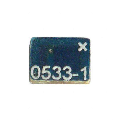
ICGOO电子元器件商城为您提供0920AT50A080E由Johanson Dielectrics Inc.设计生产,在icgoo商城现货销售,并且可以通过原厂、代理商等渠道进行代购。 0920AT50A080E价格参考。Johanson Dielectrics Inc.0920AT50A080E封装/规格:RF 天线, 920MHz 芯片 RF 天线 880MHz ~ 960MHz -0.7dBi 焊接 表面贴装。您可以下载0920AT50A080E参考资料、Datasheet数据手册功能说明书,资料中有0920AT50A080E 详细功能的应用电路图电压和使用方法及教程。
| 参数 | 数值 |
| 产品目录 | |
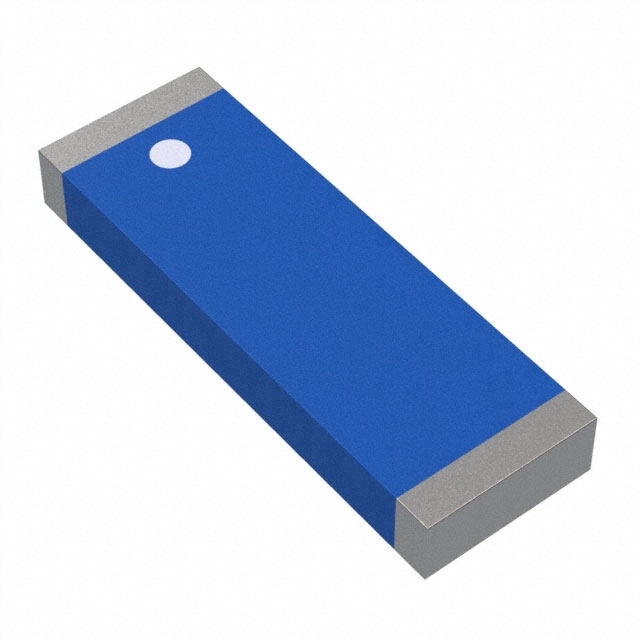
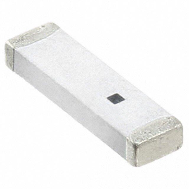
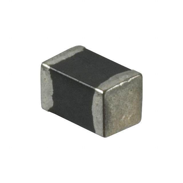
| 描述 | ANTENNA CHIP ISM 920 MHZ天线 920MHz ANTENNA |
| 产品分类 | |
| 品牌 | Johanson Technology |
| 产品手册 | |
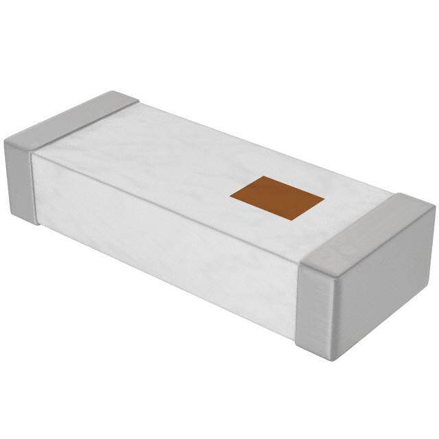
| 产品图片 |
|
| rohs | 符合RoHS不受无铅要求限制 / 符合限制有害物质指令(RoHS)规范要求 |
| 产品系列 | Johanson Technology 0920AT50A080E- |
| 数据手册 | |
| 产品型号 | 0920AT50A080E |
| VSWR | - |
| 产品培训模块 | http://www.digikey.cn/PTM/IndividualPTM.page?site=cn&lang=zhs&ptm=10258 |
| 产品目录页面 | |
| 产品种类 | 天线 |
| 其它名称 | 712-1002-6 |
| 功率额定值 | 5 W |
| 包装 | Digi-Reel® |
| 商标 | Johanson Technology |
| 增益 | - 2.6 dB |
| 天线类型 | 芯片 |
| 安装类型 | 表面贴装 |
| 安装风格 | SMD/SMT |
| 宽度 | 5.1 mm |
| 封装 | Reel |
| 尺寸 | 11 mm L x 5.1 mm W x 1.5 mm H |
| 工厂包装数量 | 1000 |
| 技术类型 | Internal SMD Chip Antenna |
| 标准包装 | 1 |
| 特色产品 | http://www.digikey.com/cn/zh/ph/Johanson/IntegratedPassives.html |
| 端接 | 表面贴装型 |
| 端接类型 | SMD/SMT |
| 系列 | 0920AT |
| 长度 | 11 mm |
| 阻抗 | 50 Ohms |
| 频带数 | 1 |
| 频率 | 920 MHz |
| 频率范围 | 880 MHz to 960 MHz |
| 高度 | 1.5 mm |
| 高度(最大值) | 0.059"(1.50mm) |



- 商务部:美国ITC正式对集成电路等产品启动337调查
- 曝三星4nm工艺存在良率问题 高通将骁龙8 Gen1或转产台积电
- 太阳诱电将投资9.5亿元在常州建新厂生产MLCC 预计2023年完工
- 英特尔发布欧洲新工厂建设计划 深化IDM 2.0 战略
- 台积电先进制程称霸业界 有大客户加持明年业绩稳了
- 达到5530亿美元!SIA预计今年全球半导体销售额将创下新高
- 英特尔拟将自动驾驶子公司Mobileye上市 估值或超500亿美元
- 三星加码芯片和SET,合并消费电子和移动部门,撤换高东真等 CEO
- 三星电子宣布重大人事变动 还合并消费电子和移动部门
- 海关总署:前11个月进口集成电路产品价值2.52万亿元 增长14.8%
PDF Datasheet 数据手册内容提取
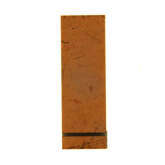
"High Frequency Ceramic Solutions" 920 MHz Antenna P/N 0920AT50A080 Detail Specification: 11/26/12 Page 1 of 3 General Specifications Part Number 0920AT50A080 Impedance 50 Ω Frequency (MHz) 880 - 960 Mhz Input Power 5W max. Peak Gain (XZ-total) -0.7 dBi typ. Operating Temperature -40 to +85°C Average Gain (XZ-tota -2.6 dBi typ. Reel Quanity 1,000 Return Loss 8.5 dB max. Part Number Explanation Bulk Suffix = S eg. 0920AT50A080S Packing Style T & R Suffix = E eg. 0920AT50A080E P/N Suffix 100% Tin Suffix = E or S eg. 0920AT50A080(E or S) Termination style Tin / Lead Please Consult Factory Mechanical Dimensions Terminal Configuration In mm No. Function L 0.433 ± 0.012 11.00 ± 0.30 1 NC W 0.201 ± 0.012 5.10 ± 0.30 2 Feeding Point T 0.059 ± 0.008 1.50 ± 0.20 3 NC a 0.039 ± 0.008 1.00 ± 0.20 4 NC b 0.020 ± 0.012 0.50 ± 0.30 5 NC c 0.020 ± 0.012 0.50 ± 0.30 6 NC b c 7 NC 8 NC 4 a W 6 1 7 2 8 3 L T 5 Mounting Considerations Mount these devices with brown mark facing up. Units: mm Line width JTI P/N for Matching Circuit: Cap (3.9pF): 500R07S3R9BV4T should be designed to provide 50 Ω impedance matching characteristics. Inductor (10nH): L-07C10NJV6T Via 1.5 mm 9.6 mm 0.7 mm 1.3 mm 3.9 pF 5.5 mm 4.5 mm 4.3 pF 0 Ohm 0.7 mm 10 nH 0.8 0. 6mm 0.7 mm 12.6 mm a) Without Matching Circuits b) With Matching Circuits www.johansontechnology.com 4001 Calle Tecate • Camarillo, CA 93012 • TEL 805.389.1166 FAX 805.389.1821 Ver 1.0 2012 Johanson Technology, Inc. All Rights Reserved
"High Frequency Ceramic Solutions" 920 MHz Antenna P/N 0920AT50A080 Detail Specification: 11/26/12 Page 2 of 3 Typical Electrical Characteristics (T=25°C) Test Board 80.1 mm ) ) 50 Ohm feed line Shorting Piece 40 mm 31.9 mm 96. 2 mm Ground clearance Return Loss a) Without Matching Circuits Johanson Technology, Inc. reserves the right to make design changes without notice. Please confirm the specifications and delivery conditions when placing your order. All sales are subject to Johanson Technology, Inc. terms and conditions. www.johansontechnology.com 4001 Calle Tecate • Camarillo, CA 93012 • TEL 805.389.1166 FAX 805.389.1821 Ver 1.0 2012 Johanson Technology, Inc. All Rights Reserved
"High Frequency Ceramic Solutions" 920 MHz Antenna P/N 0920AT50A080 Detail Specification: 11/26/12 Page 3 of 3 Typical Electrical Characteristics (T=25°C) Test Board 80.1 mm ) ) ) 50 Ohm feed Matching Circuit 40 mm ) 31.9 mm 96. 2 Ground clearance Return Loss b) With Matching Circuits Johanson Technology, Inc. reserves the right to make design changes without notice. Please confirm the specifications and delivery conditions when placing your order. All sales are subject to Johanson Technology, Inc. terms and conditions. www.johansontechnology.com 4001 Calle Tecate • Camarillo, CA 93012 • TEL 805.389.1166 FAX 805.389.1821 Ver 1.0 2012 Johanson Technology, Inc. All Rights Reserved
"High Frequency Ceramic Solutions" 920 MHz Antenna P/N 0920AT50A080 Detail Specification: 11/26/12 Page 3 of 3 Typical Electrical Characteristics (T=25°C) Typical Radiation Patterns XY cut @ 920 MHz Vertical XY-V/XY-H Z Horizontal 180° X 90° 270° Y 0° XY-cut scanning direction XZ-V/XZ-H XZ cut @ 920 MHz Y Vertical Horizontal 180° X 90° 2 70° Z 0° XZ-cut scanning direction ) YZ cut @ 920 MHz YZ-V/YZ-H X Vertical Horizontal 180° Y 90° 2 70° Z 0° YZ-cut scanning direction Johanson Technology, Inc. reserves the right to make design changes without notice. Please confirm the specifications and delivery conditions when placing your order. All sales are subject to Johanson Technology, Inc. terms and conditions. www.johansontechnology.com 4001 Calle Tecate • Camarillo, CA 93012 • TEL 805.389.1166 FAX 805.389.1821 Ver 1.0 2012 Johanson Technology, Inc. All Rights Reserved
 Datasheet下载


