- 型号: 0440008.WR
- 制造商: Littelfuse
- 库位|库存: xxxx|xxxx
- 要求:
| 数量阶梯 | 香港交货 | 国内含税 |
| +xxxx | $xxxx | ¥xxxx |
查看当月历史价格
查看今年历史价格
0440008.WR产品简介:
ICGOO电子元器件商城为您提供0440008.WR由Littelfuse设计生产,在icgoo商城现货销售,并且可以通过原厂、代理商等渠道进行代购。 0440008.WR价格参考。Littelfuse0440008.WR封装/规格:保险丝, 8A 32V AC 32V DC Fuse Board Mount (Cartridge Style Excluded) Surface Mount 1206 (3216 Metric)。您可以下载0440008.WR参考资料、Datasheet数据手册功能说明书,资料中有0440008.WR 详细功能的应用电路图电压和使用方法及教程。
| 参数 | 数值 |
| 产品目录 | |
| DC冷态电阻 | 0.00634 欧姆 |
| 描述 | FUSE 32V HIGH I2T 1206 8A表面贴装式保险丝 32V High I2T 1206 8A |
| 产品分类 | |
| 品牌 | Littelfuse |
| 产品手册 | |
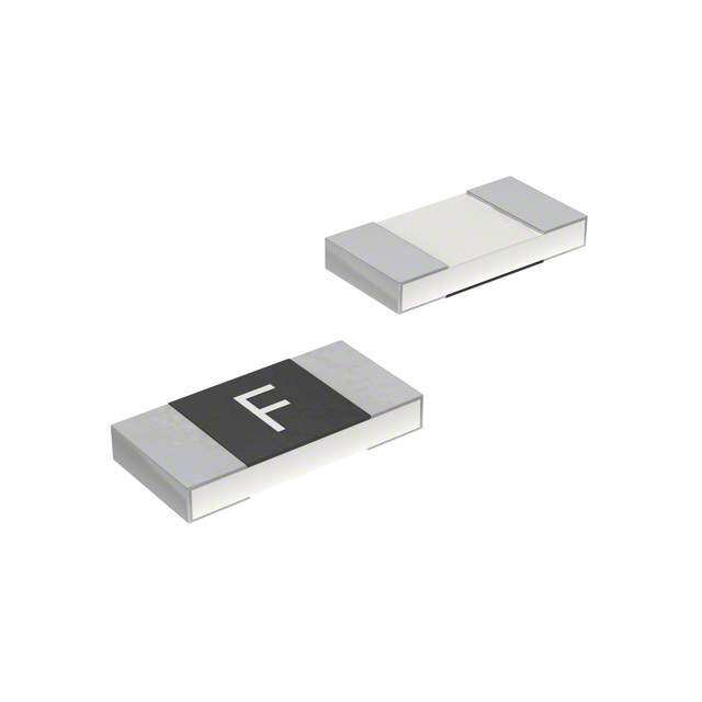
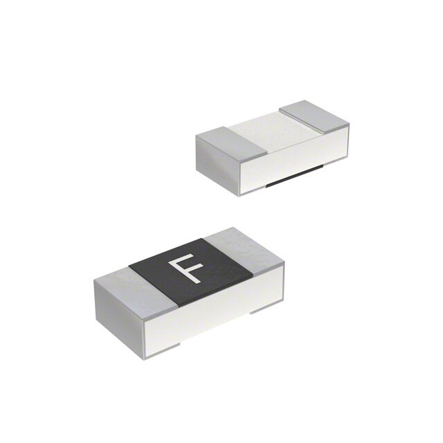
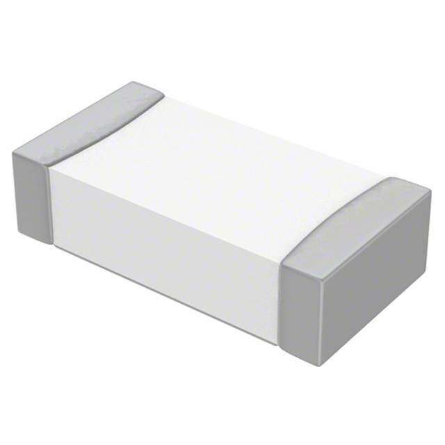
| 产品图片 |
|
| rohs | 符合RoHS无铅 / 符合限制有害物质指令(RoHS)规范要求 |
| 产品系列 | 表面贴装式保险丝,Littelfuse 0440008.WR440 |
| mouser_ship_limit | 该产品可能需要其他文件才能进口到中国。 |
| 数据手册 | |
| 产品型号 | 0440008.WR |
| 不同额定电压时的熔断能力 | 50A |
| 中断额定值 | 50 Amps at 32 VoltsDC |
| 产品 | Surface Mount Fuses |
| 产品种类 | 表面贴装式保险丝 |
| 产品类型 | Surface Mount Fuse |
| 保险丝大小/组 | 1206 (3216 metric) |
| 保险丝类型 | Fast Blow |
| 其它名称 | F1610-1 |
| 包装 | 剪切带 (CT) |
| 响应时间 | 快速 |
| 商标 | Littelfuse |
| 外壳宽度 | 1.63 mm |
| 外壳长度 | 3.2 mm |
| 外壳高度 | 0.8 mm |
| 大小/尺寸 | 0.126" 长 x 0.064" 宽 x 0.032" 高(3.20mm x 1.63mm x 0.82mm) |
| 安装类型 | 表面贴装 |
| 封装 | Reel |
| 封装/外壳 | 1206(3216 公制) |
| 尺寸 | 3.2 mm L x 1.63 mm W |
| 工作温度 | -55°C ~ 150°C |
| 工作温度范围 | - 55 C to + 150 C |
| 工厂包装数量 | 3000 |
| 标准包装 | 1 |
| 电压额定值AC | 32 V |
| 电压额定值DC | 32 V |
| 电流额定值 | 8 A |
| 电阻 | 6.46 mOhms |
| 类型 | Ceramic Surface Mount Fuse |
| 系列 | 440 |
| 融断I²t | 12.95 |
| 认可 | CSA,UL |
| 颜色 | - |
| 额定电压-AC | 32V |
| 额定电压-DC | 32V |
| 额定电流 | 8A |






- 商务部:美国ITC正式对集成电路等产品启动337调查
- 曝三星4nm工艺存在良率问题 高通将骁龙8 Gen1或转产台积电
- 太阳诱电将投资9.5亿元在常州建新厂生产MLCC 预计2023年完工
- 英特尔发布欧洲新工厂建设计划 深化IDM 2.0 战略
- 台积电先进制程称霸业界 有大客户加持明年业绩稳了
- 达到5530亿美元!SIA预计今年全球半导体销售额将创下新高
- 英特尔拟将自动驾驶子公司Mobileye上市 估值或超500亿美元
- 三星加码芯片和SET,合并消费电子和移动部门,撤换高东真等 CEO
- 三星电子宣布重大人事变动 还合并消费电子和移动部门
- 海关总署:前11个月进口集成电路产品价值2.52万亿元 增长14.8%


PDF Datasheet 数据手册内容提取
Surface Mount Fuses Ceramic Fuse > 440 Series 440 Series, 1206 High I2t Fuse RoHS Pb Description The 440 Series is a 100% Lead-free, RoHS compliant and Halogen-free fuse series designed specifically to provide over-current protection to circuits that operate under high working ambient temperatures up to 150ºC and high inrush currents. The general design ensures excellent temperature stability and performance reliability. This high I2t fuse series is designed to have ultra high inrush current withstand capability to avoid nuisance fuse open. Features • Operating Temperature • Suitable for both leaded from -55ºC to +150ºC and lead-free reflow / wave soldering • 100% Lead-free, RoHS compliant and Halogen-free • Ultra high I2t values Agency Approvals Applications AGENCY AGENCY FILE NUMBER AMPERE RANGE • LCD Displays • Scanners E10480 0.25A - 8A • Servers • Data Modems 29862 0.25A - 8A • Notebook Computers • Hard Disk Drives • Printers Electrical Characteristics for Series Additional Information % of Ampere Ampere Rating Opening Time at 25ºC Rating 100% 0.25A - 8A 4 hours, Minimum 350% 0.25A - 8A 5 secs., Maximum Datasheet Resources Samples Electrical Specifications by Item Ampere Max. Nominal Nominal Nominal Voltage Nominal Power Agency Approvals Amp Interrupting Rating Rating Voltage Resistance Melting I2t Drop At Rated Dissipation At Code (AC/DC)1 (A) Rating (V) (Ohms)2 (A2Sec.)3 Current (V)4 Rated Current (W) 0.250 .250 125 2.140 0.00649 0.5260 0.132 x X 50 A @ 125 V AC/DC 0.375 .375 125 1.216 0.01455 0.4993 0.187 x X 0.500 .500 63 50 A @ 63 V AC/DC 0.8140 0.02642 0.4831 0.242 x X 0.750 .750 63 50 A @ 63 V AC/DC 0.4624 0.09312 0.3983 0.299 x X 1.00 001. 50 0.3096 0.21054 0.3457 0.346 x X 50 A @ 50 V DC 1.25 1.25 50 0.2265 0.379 0.3240 0.405 x X 50 A @ 50 V AC 1.50 01.5 50 0.1759 0.50652 0.3215 0.482 x X 1.75 1.75 32 0.0450 0.3312 0.0777 0.136 x X 2.00 002. 32 0.0385 0.4326 0.0792 0.158 x X 2.50 02.5 32 0.02850 0.8191 0.0747 0.187 x X 3.00 003. 32 0.02252 1.232 0.0742 0.223 x X 3.50 03.5 32 50 A @ 32 V AC/DC 0.01845 1.789 0.0757 0.265 x X 4.00 004. 32 0.01553 2.601 0.0709 0.284 x X 5.00 005. 32 0.0120 4.761 0.0654 0.327 x X 7.00 007. 32 0.00753 8.464 0.0696 0.487 x X 8.00 008. 32 0.00634 12.95 0.0655 0.524 x X Notes: 1. AC Interrupting Rating tested at rated voltage with unity power factor. DC Interrupting Devices designed to carry rated current for 4 hours minimum. It is recommended that Rating tested at rated voltage with time constant < 0.8 msec. devices be operated continuously at no more than 80% rated current. See “Temperature 2. Nominal Resistance measured with < 10% rated current. Derating Curve”for additional derating information. 3. Contact Littelfuse if application transient surges are less than 1 ms. Devices designed to be mounted with marking code facing up. 4. Nominal Voltage Drop measured at rated current after temperature has stabilized. © 2018 Littelfuse, Inc. Specifications are subject to change without notice.Application testing is strongly recommended. Revised: 12/13/18
Surface Mount Fuses Ceramic Fuse > 440 Series Temperature Rerating Curve Average Time Current Curves 140 100 G120 N TI A R100 F 10 O T N80 E C R E P60 S D 1 N O C 40 E S -65 -45 -25 -5 15 35 55 75 95 115 135 155 N TEMPERATURE (°C) E I M TI 0.1 Note: 1. Rerating depicted in this curve is in addition to the standard derating of 20% for continuous operation. 0.01 Example: For continuous operation at 75 degrees celsius, the fuse should be derated as follows: I = (0.80)(0.85)I = (0.68)I RAT RAT 0.001 0.1 1.0 10.0 100.0 1000. CURRENT IN AMPERES Soldering Parameters Reflow Condition Pb-free assembly tP T P Critical Zone - Temperature Min (T ) 150°C Ramp-up TL to TP s(min) T Pre Heat -- TTeimmep e(Mraitnu rteo MMaaxx )( T(ts()max)) 2600 0–° C180 seconds eruTS(maxL) tL s ta Average Ramp-Up Rate (Liquidus Temp re Ramp-down 3°C/second max. p Preheat (T) to peak) mT L S(min) T to T - Ramp-up Rate 5°C/second max. eT tS S(max) L - Temperature (T) (Liquidus) 217°C Reflow L 25 - Temperature (tL) 60 – 150 seconds time (tto 2 p5eºCak t ote pmepaekr)ature Time Peak Temperature (T ) 260+0/-5 °C P Time within 5°C of actual peak 10 – 30 seconds Temperature (t ) p Ramp-down Rate 6°C/second max. Time 25°C to peak Temperature (T ) 8 minutes max. P Do not exceed 260°C Wave Soldering 260°C, 10 seconds max. © 2018 Littelfuse, Inc. Specifications are subject to change without notice. Revised: 12/13/18
Surface Mount Fuses Ceramic Fuse > 440 Series Product Characteristics Moisture Resistance MIL-STD-202, Method 106 Body: Advanced Ceramic Materials Terminations: Ag / Ni / Sn (100% Lead-free) MIL-STD-202, Method 107, Thermal Shock Element Cover Coating: Lead-free Glass Condition B MIL-STD-202, Method 213, Moisture Mechanical Shock Condition A IPC/JEDEC J-STD-020, Level 1 Sensitivity Level Vibration MIL-STD-202, Method 201 Solderability IPC/ECA/JEDEC J-STD-002, Condition C Vibration, MIL-STD-202, Method 204, High Frequency Condition D Humidity Test MIL-STD-202, Method 103, Conditions D Dissolution of IPC/ECA/JEDEC J-STD-002, Metallization Condition D Resistance to MIL-STD-202, Method 210, Condition B Solder Heat Terminal Strength IEC 60127-4 Dimensions Part Marking System Amp Code Marking Code Amp Code Marking Code 3.200 ± .1778 [.126 ± .007] .250 D 002. N .375 E 02.5 O X .500 F 003. P .750 G 03.5 R 1.000 1.63 + .10/ -.20 [.039] [.064 + .004/ -.008] 001. H 004. S 1.25 J 005. T 01.5 K 007. W 1.75 L 008. X Part Numbering System .8179 +.046/ -.076 [.0322 +.0018/ -.003] 0440 008. W R TERMINATION SERIES AMP CODE QUANTITY CODE W = 3000 pcs 0.520 ± .200 [.020 ± .008] PACKING CODE R = Reel Pack 1.000 1.500 [.039] [.059] Packaging 1.800 [.071] Packaging Packaging Quantity & Quantity Option Specification Packaging Code 3.500 [.138] 8mm Tape EIA-481, IEC 60286, 3000 WR and Reel Part 3 Disclaimer Notice - Littelfuse products are not designed for, and shall not be used for, any purpose (including, without limitation, automotive, military, aerospace, medical, life-saving, life-sustaining or nuclear facility applications, devices intended for surgical implant into the body, or any other application in which the failure or lack of desired operation of the product may result in personal injury, death, or property damage) other than those expressly set forth in applicable Littelfuse product documentation. Warranties granted by Littelfuse shall be deemed void for products used for any purpose not expressly set forth in applicable Littelfuse documentation. Littelfuse shall not be liable for any claims or damages arising out of products used in applications not expressly intended by Littelfuse as set forth in applicable Littelfuse documentation. The sale and use of Littelfuse products is subject to Littelfuse Terms and Conditions of Sale, unless otherwise agreed by Littelfuse. Information furnished is believed to be accurate and reliable. However, users should independently evaluate the suitability of and test each product selected for their own applications. Littelfuse products are not designed for, and may not be used in, all applications. Read complete Disclaimer Notice at www.littelfuse.com/disclaimer-electronics. © 2018 Littelfuse, Inc. Specifications are subject to change without notice. Revised: 12/13/18
 Datasheet下载

