 Datasheet下载
- 型号: 0306ZD224KAT2A
- 制造商: AVX
- 库位|库存: xxxx|xxxx
- 要求:
| 数量阶梯 | 香港交货 | 国内含税 |
| +xxxx | $xxxx | ¥xxxx |
查看当月历史价格
查看今年历史价格
0306ZD224KAT2A产品简介:
ICGOO电子元器件商城为您提供0306ZD224KAT2A由AVX设计生产,在icgoo商城现货销售,并且可以通过原厂、代理商等渠道进行代购。 0306ZD224KAT2A价格参考。AVX0306ZD224KAT2A封装/规格:陶瓷电容器, 0.22µF ±10% 10V 陶瓷电容器 X5R 0306(0816 公制)。您可以下载0306ZD224KAT2A参考资料、Datasheet数据手册功能说明书,资料中有0306ZD224KAT2A 详细功能的应用电路图电压和使用方法及教程。
| 参数 | 数值 |
| 产品目录 | |
| 描述 | CAP CER 0.22UF 10V 10% X5R 0306多层陶瓷电容器MLCC - SMD/SMT 10volts 0.22uF |
| 产品分类 | |
| 品牌 | AVX |
| 产品手册 | |
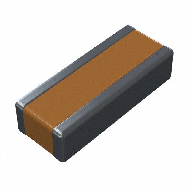
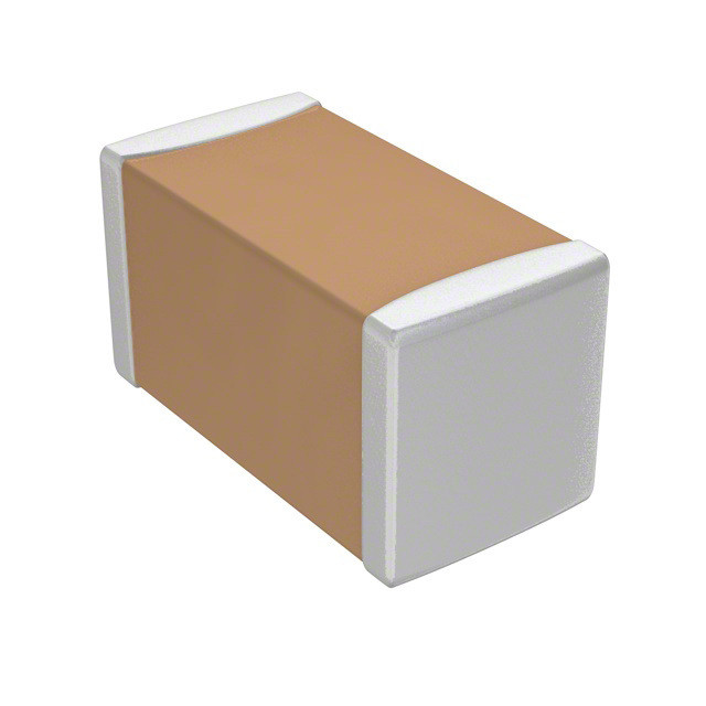
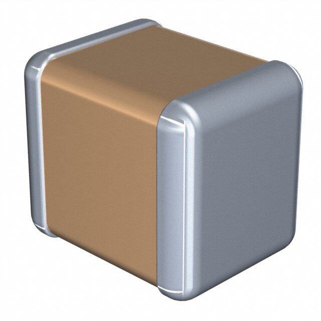
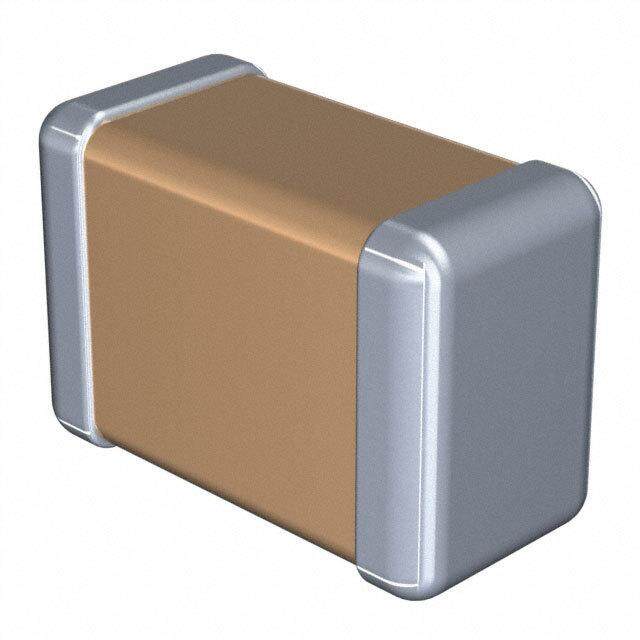
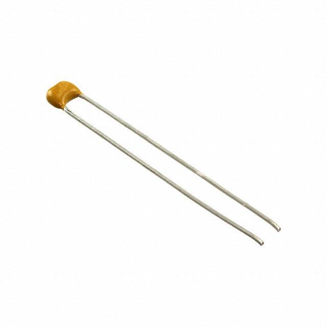
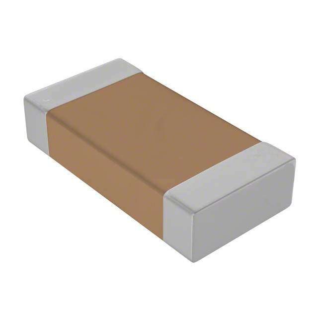
| 产品图片 |
|
| rohs | 符合RoHS无铅 / 符合限制有害物质指令(RoHS)规范要求 |
| 产品系列 | MLCC,多层陶瓷电容器MLCC - SMD/SMT,AVX 0306ZD224KAT2A- |
| 数据手册 | |
| 产品型号 | 0306ZD224KAT2A |
| 产品 | Reverse Geometry Type MLCCs |
| 产品培训模块 | http://www.digikey.cn/PTM/IndividualPTM.page?site=cn&lang=zhs&ptm=21795 |
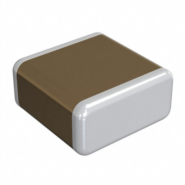
| 产品目录绘图 |
|
| 产品种类 | 多层陶瓷电容器MLCC - SMD/SMT |
| 其它名称 | 478-6191-6 |
| 包装 | Digi-Reel® |
| 厚度(最大值) | 0.024"(0.61mm) |
| 商标 | AVX |
| 外壳代码-in | 0306 (Reversed) |
| 外壳代码-mm | 0816 (Reversed) |
| 外壳宽度 | 1.52 mm |
| 外壳长度 | 0.31 mm |
| 外壳高度 | 0.51 mm |
| 大小/尺寸 | 0.032" 长 x 0.063" 宽(0.81mm x 1.60mm) |
| 安装类型 | 表面贴装,MLCC |
| 容差 | 10 % |
| 封装 | Reel |
| 封装/外壳 | 0306(0816 公制) |
| 封装/箱体 | 0306 (Reversed) |
| 工作温度 | -55°C ~ 85°C |
| 工作温度范围 | - 55 C to + 125 C |
| 工厂包装数量 | 5000 |
| 应用 | 旁通,去耦 |
| 引线形式 | - |
| 引线间距 | - |
| 最大工作温度 | + 85 C |
| 最小工作温度 | - 55 C |
| 标准包装 | 1 |
| 温度系数 | X5R |
| 温度系数/代码 | +/- 15 % |
| 特性 | 低 ESL 型(倒置结构) |
| 电介质 | X5R |
| 电压-额定 | 10V |
| 电压额定值 | 10 V |
| 电压额定值DC | 10 V |
| 电容 | 0.022 uF |
| 端接类型 | SMD/SMT |
| 等级 | - |
| 类型 | Low Inductance Capacitor, Reversed |
| 高度-安装(最大值) | - |


- 商务部:美国ITC正式对集成电路等产品启动337调查
- 曝三星4nm工艺存在良率问题 高通将骁龙8 Gen1或转产台积电
- 太阳诱电将投资9.5亿元在常州建新厂生产MLCC 预计2023年完工
- 英特尔发布欧洲新工厂建设计划 深化IDM 2.0 战略
- 台积电先进制程称霸业界 有大客户加持明年业绩稳了
- 达到5530亿美元!SIA预计今年全球半导体销售额将创下新高
- 英特尔拟将自动驾驶子公司Mobileye上市 估值或超500亿美元
- 三星加码芯片和SET,合并消费电子和移动部门,撤换高东真等 CEO
- 三星电子宣布重大人事变动 还合并消费电子和移动部门
- 海关总署:前11个月进口集成电路产品价值2.52万亿元 增长14.8%


PDF Datasheet 数据手册内容提取
Low Inductance Capacitors Introduction The signal integrity characteristics of a Power Delivery Network (PDN) The ESL of a capacitor determines the speed of energy transfer to a are becoming critical aspects of board level and semiconductor load. The lower the ESL of a capacitor, the faster that energy can be package designs due to higher operating frequencies, larger power transferred to a load. Historically, there has been a tradeoff between demands, and the ever shrinking lower and upper voltage limits around energy storage (capacitance) and inductance (speed of energy low operating voltages. These power system challenges are coming delivery). Low ESL devices typically have low capacitance. Likewise, from mainstream designs with operating frequencies of 300MHz higher capacitance devices typically have higher ESLs. This tradeoff or greater, modest ICs with power demand of 15 watts or more, and between ESL (speed of energy delivery) and capacitance (energy operating voltages below 3 volts. storage) drives the PDN design topology that places the fastest low ESL capacitors as close to the load as possible. Low Inductance MLCCs are The classic PDN topology is comprised of a series of capacitor stages. found on semiconductor packages and on boards as close as possible Figure 1 is an example of this architecture with multiple capacitor to the load. stages. An ideal capacitor can transfer all its stored energy to a load instantly. A real capacitor has parasitics that prevent instantaneous transfer of a capacitor’s stored energy. The true nature of a capacitor can be modeled as an RLC equivalent circuit. For most simulation purposes, it is possible to model the characteristics of a real capacitor with one capacitor, one resistor, and one inductor. The RLC values in this model are commonly referred to as equivalent series capacitance (ESC), equivalent series resistance (ESR), and equivalent series inductance (ESL). Slowest Capacitors Fastest Capacitors Semiconductor Product VR Bulk Board-Level Package-Level Die-Level Low Inductance Decoupling Capacitors Figure 1 Classic Power Delivery Network (PDN) Architecture LOW INDUCTANCE CHIP CAPACITORS INTERDIGITATED CAPACITORS The key physical characteristic determining equivalent series inductance The size of a current loop has the greatest impact on the ESL (ESL) of a capacitor is the size of the current loop it creates. The smaller characteristics of a surface mount capacitor. There is a secondary the current loop, the lower the ESL. A standard surface mount MLCC is method for decreasing the ESL of a capacitor. This secondary method rectangular in shape with electrical terminations on its shorter sides. uses adjacent opposing current loops to reduce ESL. The InterDigitated A Low Inductance Chip Capacitor (LICC) sometimes referred to as Capacitor (IDC) utilizes both primary and secondary methods of Reverse Geometry Capacitor (RGC) has its terminations on the longer reducing inductance. The IDC architecture shrinks the distance between side of its rectangular shape. terminations to minimize the current loop size, then further reduces inductance by creating adjacent opposing current loops. When the distance between terminations is reduced, the size of the current loop is reduced. Since the size of the current loop is the An IDC is one single capacitor with an internal structure that has been primary driver of inductance, an 0306 with a smaller current loop has optimized for low ESL. Similar to standard MLCC versus LICCs, the significantly lower ESL then an 0603. The reduction in ESL varies by EIA reduction in ESL varies by EIA case size. Typically, for the same EIA size, however, ESL is typically reduced 60% or more with an LICC versus size, an IDC delivers an ESL that is at least 80% lower than an MLCC. a standard MLCC. 74
Low Inductance Capacitors Introduction LAND GRID ARRAY (LGA) CAPACITORS LOW INDUCTANCE CHIP ARRAYS (LICA®) Land Grid Array (LGA) capacitors are based on the first Low ESL The LICA® product family is the result of a joint development effort MLCC technology created to specifically address the design needs between AVX and IBM to develop a high performance MLCC family of of current day Power Delivery Networks (PDNs). This is the 3rd low decoupling capacitors. LICA was introduced in the 1980s and remains inductance capacitor technology developed by AVX. LGA technology the leading choice of designers in high performance semiconductor provides engineers with new options. The LGA internal structure and packages and high reliability board level decoupling applications. manufacturing technology eliminates the historic need for a device to be LICA® products are used in 99.999% uptime semiconductor package physically small to create small current loops to minimize inductance. applications on both ceramic and organic substrates. The C4 solder The first family of LGA products are 2 terminal devices. A 2 terminal ball termination option is the perfect compliment to flip-chip packaging 0306 LGA delivers ESL performance that is equal to or better than an technology. Mainframe class CPUs, ultimate performance multi-chip 0306 8 terminal IDC. The 2 terminal 0805 LGA delivers ESL performance modules, and communications systems that must have the reliability that approaches the 0508 8 terminal IDC. New designs that would have of 5 9’s use LICA®. used 8 terminal IDCs are moving to 2 terminal LGAs because the layout LICA® products with either Sn/Pb or Pb-free solder balls are used for is easier for a 2 terminal device and manufacturing yield is better for a decoupling in high reliability military and aerospace applications. These 2 terminal LGA versus an 8 terminal IDC. LICA® devices are used for decoupling of large pin count FPGAs, ASICs, LGA technology is also used in a 4 terminal family of products that AVX CPUs, and other high power ICs with low operating voltages. is sampling and will formerly introduce in 2008. Beyond 2008, there are When high reliability decoupling applications require the very lowest new multi-terminal LGA product families that will provide even more ESL capacitors, LICA® products are the best option. attractive options for PDN designers. 470 nF 0306 Impedance Comparison 1 0306 2T-LGA 0306 LICC 0306 8T-IDC 0603 MLCC s) 0.1 m h o e ( c n a d e p m 0.01 I 0.001 1 10 100 1000 Frequency (MHz) Figure 2 MLCC, LICC, IDC, and LGA technologies deliver different levels of equivalent series inductance (ESL). 75
Low Inductance Ceramic Capacitors LICC (Low Inductance Chip Capacitors) 0306/0508/0612 RoHS Compliant GENERAL DESCRIPTION The key physical characteristic determining equivalent series inductance (ESL) of a capacitor is the size of the current loop it creates. The smaller the current loop, the lower the ESL. A standard surface mount MLCC is rectangular in shape with electrical terminations on its shorter sides. A Low Inductance Chip Capacitor (LICC) sometimes referred to as Reverse Geometry Capacitor (RGC) has its terminations on the longer sides of its rectangular shape. The image on the right shows the termination differences between an MLCC and an LICC. When the distance between terminations is reduced, the size of the current loop is reduced. Since the size of the current loop is the primary driver of inductance, an 0306 with a smaller current loop has significantly lower ESL then an 0603. The reduction in ESL varies by EIA size, however, ESL is typically reduced 60% or more with an LICC versus a standard MLCC. MLCC LICC AVX LICC products are available with a lead-free finish of plated Nickel/Tin. PERFORMANCE CHARACTERISTICS Capacitance Tolerances K = ±10%; M = ±20% X7R = -55°C to +125°C Operation X5R = -55°C to +85°C Temperature Range X7S = -55°C to +125°C Temperature Coefficient X7R, X5R = ±15%; X7S = ±22% Voltage Ratings 4, 6.3, 10, 16, 25 VDC 4V, 6.3V = 6.5% max; 10V = 5.0% max; Dissipation Factor 16V = 3.5% max; 25V = 3.0% max Insulation Resistance 100,000MΩ min, or 1,000MΩ per μF (@+25°C, RVDC) min.,whichever is less HOW TO ORDER 0612 Z D 105 M A T 2 A* Size Voltage Dielectric Capacitance Capacitance Failure Rate Terminations Packaging Thickness 0306 4 = 4V C = X7R Code (In pF) Tolerance A = N/A T = Plated Ni Available Thickness 0508 6 = 6.3V D = X5R 2 Sig. Digits + K = ±10% 4 = Automotive** and Sn 2 = 7" Reel mm (in) 0612 Z = 10V W = X6S Number of Zeros M = ±20% 4 = 13" Reel 0.56 (0.022) Y = 16V Z = X7S 0.76 (0.030) 3 = 25V 1.02 (0.040) 5 = 50V 1.27 (0.050) *See the thickness tables on the next page. **Select voltages for Automotive version, contact factory NOTE: Contact factory for availability of Termination and Tolerance Options for Specific Part Numbers. TYPICAL IMPEDANCE CHARACTERISTICS 76 081919
Low Inductance Ceramic Capacitors 0306/0508/0612 RoHS Compliant LICC (Low Inductance Chip Capacitors) 0306/0508/0612 RoHS Compliant PHYSICAL DIMENSIONS AND SIZE 0306 0508 0612 Packaging Embossed Embossed Embossed PAD LAYOUT mm 0.81 + 0.15 1.27 + 0.25 1.60 + 0.25 Length (in.) (0.032 ± 0.006) (0.050 ± 0.010) (0.063 ± 0.010) mm 1.60 + 0.15 2.00 + 0.25 3.20 + 0.25 Width (in.) (0.063 ± 0.006) (0.080 ± 0.010) (0.126 ± 0.010) Cap Code WVDC 4 6.3 10 16 25 6.3 10 16 25 50 6.3 10 16 25 50 W t 102 Cap 0.001 A A A A S S S S V S S S S V 222 (μF) .0022 A A A A S S S S V S S S S V 332 0.0033 A A A A S S S S V S S S S V T 472 0.0047 A A A A S S S S V S S S S V 682 0.0068 A A A A S S S S V S S S S V L 103 0.01 A A A A S S S S V S S S S V 153 0.015 A A A A S S S S V S S S S W 223 0.022 A A A A S S S S V S S S S W 333 0.033 A A A S S S V V S S S S W 473 0.047 A A A S S S V A S S S S W PHYSICAL DIMENSIONS 683 0.068 A A A S S S A A S S S V W mm (in.) 104 0.1 A A A S S V A A S S S V W Size L W t 154 0.15 A A S S V S S S W W 0.81 ± 0.15 1.60 ± 0.15 0.13 min. 224 0.22 A A S S A S S V W 0306 (0.032 ± 0.006) (0.063 ± 0.006) (0.005 min.) 334 0.33 V V A S S V 1.27 ± 0.25 2.00 ± 0.25 0.13 min. 474 0.47 V V A S S V 0508 (0.050 ± 0.010) (0.080 ± 0.010) (0.005 min.) 684 0.68 A A V V W 1.60 ± 0.25 3.20 ± 0.25 0.13 min. 105 1 A A A V V A 0612 (0.063 ± 0.010) (0.126 ± 0.010) (0.005 min.) 155 1.5 A W W 225 2.2 A A T - See Range Chart for Thickness and Codes 335 3.3 A 475 4.7 PAD LAYOUT DIMENSIONS 685 6.8 106 10 mm (in.) Size A B C Solid = X7R = X5R = X7S = X6S 0306 0.31 (0.012) 1.52 (0.060) 0.51 (0.020) 0508 0.51 (0.020) 2.03 (0.080) 0.76 (0.030) 0612 0.76 (0.030) 3.05 (0.120) 0.635 (0.025) mm (in.) mm (in.) mm (in.) 0306 0508 0612 Code Thickness Code Thickness Code Thickness A 0.56 (0.022) S 0.56 (0.022) S 0.56 (0.022) V 0.76 (0.030) V 0.76 (0.030) A 1.02 (0.040) W 1.02 (0.040) A 1.27 (0.050) “B” C “A” C 77 041416