- 型号: 0157010.DR
- 制造商: Littelfuse
- 库位|库存: xxxx|xxxx
- 要求:
| 数量阶梯 | 香港交货 | 国内含税 |
| +xxxx | $xxxx | ¥xxxx |
查看当月历史价格
查看今年历史价格
0157010.DR产品简介:
ICGOO电子元器件商城为您提供0157010.DR由Littelfuse设计生产,在icgoo商城现货销售,并且可以通过原厂、代理商等渠道进行代购。 0157010.DR价格参考。Littelfuse0157010.DR封装/规格:保险丝, 10A 125V AC 125V DC Fuse Board Mount (Cartridge Style Excluded) Holder, Surface Mount 2-SMD, Square End Block with Clip。您可以下载0157010.DR参考资料、Datasheet数据手册功能说明书,资料中有0157010.DR 详细功能的应用电路图电压和使用方法及教程。
| 参数 | 数值 |
| 产品目录 | |
| DC冷态电阻 | 0.0058 欧姆 |
| 描述 | FUSE BRD MNT 10A 125VAC/VDC SMD表面贴装式保险丝 260C 10A SMF NANO CLIP VFA |
| 产品分类 | |
| 品牌 | Littelfuse |
| 产品手册 | |
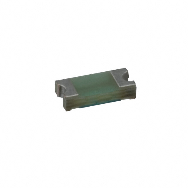
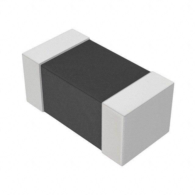
| 产品图片 |
|
| rohs | 符合RoHS无铅 / 符合限制有害物质指令(RoHS)规范要求 |
| 产品系列 | 表面贴装式保险丝,Littelfuse 0157010.DRNANO²® 157 |
| mouser_ship_limit | 该产品可能需要其他文件才能进口到中国。 |
| 数据手册 | |
| 产品型号 | 0157010.DR |
| 不同额定电压时的熔断能力 | 35A AC,50A DC |
| 中断额定值 | 35 Amps at 125 VoltsAC / 300 Amps at 32 VoltsDC / 50 Amps at 125 VoltsDC |
| 产品 | Surface Mount Fuses |
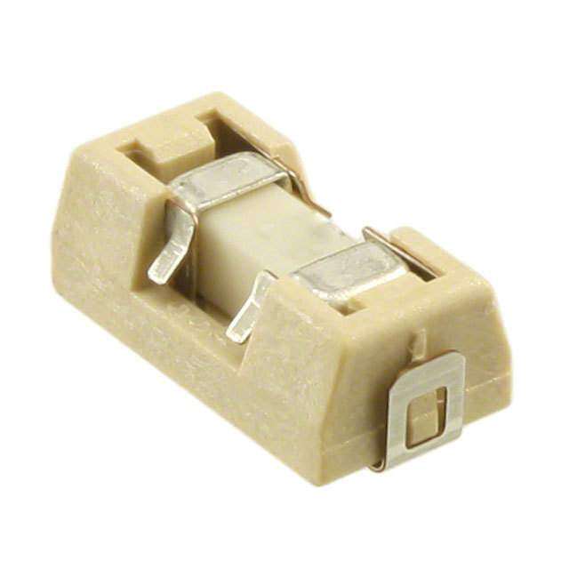
| 产品目录绘图 |
|
| 产品目录页面 | |
| 产品种类 | 表面贴装式保险丝 |
| 产品类型 | Surface Mount Fuse with Fuse Holder |
| 保险丝大小/组 | NANO |
| 保险丝类型 | Fast Blow |
| 其它名称 | F2973CT |
| 包装 | 剪切带 (CT) |
| 响应时间 | 快速 |
| 商标 | Littelfuse |
| 外壳宽度 | 2.69 mm |
| 外壳长度 | 6.5 mm |
| 外壳高度 | 2.69 mm |
| 大小/尺寸 | 0.256" 长 x 0.146" 宽 x 0.154" 高 (6.50mm x 3.70mm x 3.90mm) |
| 安装类型 | 支座/表面贴装 |
| 封装 | Reel |
| 封装/外壳 | 2-SMD,带夹子的方形端块 |
| 尺寸 | 6.5 mm L x 2.69 mm W |
| 工作温度 | -55°C ~ 125°C |
| 工作温度范围 | - 55 C to + 125 C |
| 工厂包装数量 | 1500 |
| 标准包装 | 1 |
| 电压额定值AC | 125 V |
| 电压额定值DC | 125 V |
| 电流额定值 | 10 A |
| 电阻 | 5.8 mOhms |
| 类型 | Nano SMD/SMT Fuse and Holder Combination |
| 系列 | 157 |
| 融断I²t | 26.46 |
| 认可 | cULus,PSE |
| 颜色 | - |
| 额定电压-AC | 125V |
| 额定电压-DC | 125V |
| 额定电流 | 10A |





- 商务部:美国ITC正式对集成电路等产品启动337调查
- 曝三星4nm工艺存在良率问题 高通将骁龙8 Gen1或转产台积电
- 太阳诱电将投资9.5亿元在常州建新厂生产MLCC 预计2023年完工
- 英特尔发布欧洲新工厂建设计划 深化IDM 2.0 战略
- 台积电先进制程称霸业界 有大客户加持明年业绩稳了
- 达到5530亿美元!SIA预计今年全球半导体销售额将创下新高
- 英特尔拟将自动驾驶子公司Mobileye上市 估值或超500亿美元
- 三星加码芯片和SET,合并消费电子和移动部门,撤换高东真等 CEO
- 三星电子宣布重大人事变动 还合并消费电子和移动部门
- 海关总署:前11个月进口集成电路产品价值2.52万亿元 增长14.8%
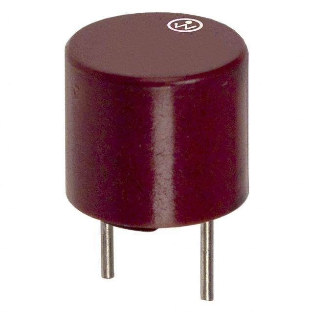
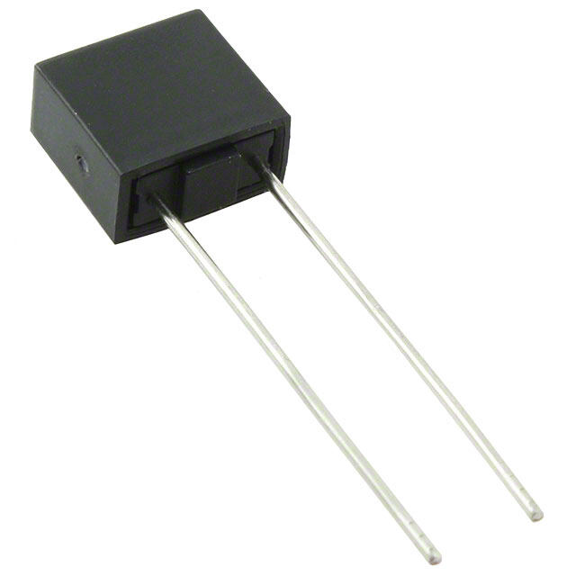

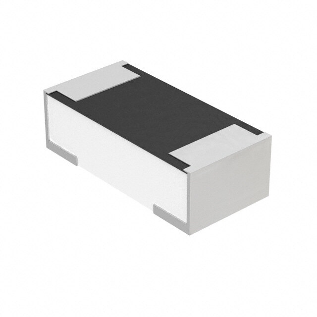

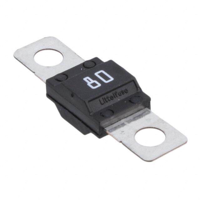
PDF Datasheet 数据手册内容提取
Surface Mount Fuses NANO2® > 157 Fuse and Holder Combination 157 Series – Standard Nano2® Fuse and Clip Assembly RoHS PS E Description The 157 Series – Standard Nano Fuse/Clip assembly is a small, square, very fast-acting surface mount fuse that is assembled in surface mountable fuse clips. The fuse clip and pre-installed fuse combination can be automatically placed in PC Board in one efficient manufacturing operation. It permits quick and easy replacement of fuses without performing desoldering process, even in the field and without exposing the PC Board to detrimental effects of rework solder heat. Features Agency Approvals • Surface Mountable assembly. • Very Fast-Acting Fuse • Easily replaceable on PC Agency Agency File Number Ampere Range Board (Field Replaceable) • Fully compatible with E14721 0.062A - 10A RoHS/Pb-Free solder • RoHS compliant and NBK030205-E10480A 1A - 1.6A alloys and higher Halogen Free PES NNBBKK013001120055--EE11804468505B 6.23AA -- 51A0A temperature profiles • Available in ratings of associated with leadfree 0.062 ~ 10 Amperes. Electrical Characteristics for Series Applications % of Ampere Rating Opening Time at 25ºC • Instrumentation • Telecommunications 100% 4 hours Minimum • Base Stations 200% 5 secs. Maximum Electrical Specifications by Item Nominal Agency Approvals Ampere Amp Max Voltage Interrupting Fuse Nominal Cold Melting Rating (A) Code Rating (V) Rating (A) Furnished Resistance (Ohms) PS I2t (A2sec) E 0.062 0.062 125 451.062 5.5372 0.00019 X - 0.08 0.08 125 451.08 4.0500 0.00033 X - 0.1 0.1 125 451.1 3.1000 0.00138 X - 0.125 0.125 125 451.125 1.7059 0.00286 X - 0.16 0.16 125 453.16 1.2157 0.0048 X - 0.2 0.2 125 453.2 1.3971 0.00652 X - 0.25 0.25 125 453.25 1.0496 0.01126 X - 0.315 0.315 125 453.315 0.3881 0.0311 X - 0.375 0.375 125 453.375 0.4518 0.0442 X - 0.4 0.4 125 453.4 0.4212 0.0551 X - 0.5 0.5 125 453.5 0.3031 0.0824 X - 0.63 0.63 125 453.63 0.2012 0.1381 X - 0.75 0.75 125 453.75 0.1437 0.2143 X - 50A @ 125 VAC/VDC 0.8 0.8 125 453.8 0.1348 0.2654 X - 1.0 1.0 125 453001.0 0.0776 0.6029 X X 300A @ 32 VDC 1.25 1.25 125 4531.25 0.078 0.664 X X 1.5 1.5 125 45301.5 0.0634 0.853 X X 1.6 1.6 125 45301.6 0.0580 1.06 X X 2.0 2.0 125 453002.0 0.0373 0.53 X X 2.5 2.5 125 45302.5 0.0288 1.029 X X 3.0 3.0 125 453003.0 0.0229 1.65 X X 3.15 3.15 125 4533.15 0.0215 1.92 X X 3.5 3.5 125 45303.5 0.0203 2.469 X X 4.0 4.0 125 453004.0 0.0163 3.152 X X 5.0 5.0 125 453005.0 0.0127 5.566 X X 6.3 6.3 125 45306.3 0.0098 9.17 X X 7.0 7.0 125 453007.0 0.0092 10.32 X X 8.0 8.0 125 453008.0 0.0079 20.23 X X 35A @ 125 VAC / 50A @125 VDC 10.0 10.0 125 453010.0 0.0058 26.46 X X 300A @ 32VDC 1. Cold resistance measured at less than 10% of rated current at 23ºC. 4. Have special electrical characteristic needs? Contact Littelfuse to learn more about application specific 2. I2t values stated for 8ms opening time. options. 3. Agency Approval Table Key: X=Approved or Certified, P=Pending and Blank=Not Approved © 2020 Littelfuse, Inc. Specifications are subject to change without notice. Revised: 03/18/20
Surface Mount Fuses NANO2® > 157 Fuse and Holder Combination Temperature Re-rating Curve Average Time Current Curves 62mA80mA100mA 125mA160mA 200mA 250mA 315mA 375mA 400mA500mA 630mA 750mA 800mA 1A 1.25A 1.5A1.6A2A2.5A3A3.15A3.5A 4A 5A 6.3A7A 8A10A 100 10 1 S D N O C SE N ME I TI 0.1 Note: 1. Rerating depicted in this curve is in addition to the standard derating of 25% for continuous operation. 0.01 0.001 0.01 0.1 1 10 100 1000 10000 CURRENT IN AMPS Soldering Parameters Reflow Condition Pb – Free assembly t P - Temperature Min (T ) 150°C T s(min) P Critical Zone Pre Heat - Temperature Max (T ) 200°C Ramp-up TL to TP s(max) - Time (Min to Max) (ts) 60 – 180 secs TL t Average ramp up rate (Liquidus Temp (TL) to peak 5°C/second max. eruTS(max) L T to T - Ramp-up Rate 5°C/second max. ta S(max) L re Ramp-down - Temperature (T) (Liquidus) 217°C p Preheat Reflow L mTS(min) - Temperature (tL) 60 – 150 seconds eT tS Peak Temperature (T) 260+0/–5 °C P Time within 5°C of actual peak Temperature (t) 20 – 40 seconds 25 p time to peak temperature Ramp-down Rate 5°C/second max. (t 25ºC to peak) Time Time 25°C to peak Temperature (T) 8 minutes max. P Do not exceed 260°C © 2020 Littelfuse, Inc. Specifications are subject to change without notice. Revised: 03/18/20
Surface Mount Fuses NANO2® > 157 Fuse and Holder Combination Product Characteristics Body: Ceramic Operating Temperature -55ºC to 125ºC with proper derating Cap: For 0.062A ~ 0.125A – Au plated Brass For 0.200A MIL-STD-202, Method 107, Materials ~ 10A – Silver plated Brass Thermal Shock Test Condition B Clip Plating: Matte Tin (5 cycles -65ºC to +125ºC) MIL-STD-202, Method 201 Product Marking Body: Brand Logo, Current Rating Vibration (10-55 Hz) Force applied at fuse center, perpendicular to the long Clip Retention MIL-STD-202, Method 106, axis (@ 0.75 lbs. MIN) Moisture Resistance 10 cycles MIL-STD-202, Method 208 / IPC/ EIA / JEDEC Solderability MIL-STD-202, Method 101, J-STD-002, Test Condition A Salt Spray/ Atmosphere Test Condition B (48 hrs.), Humidity Test MIL –STD-202, Method 103 @ 85ºC / 85%RH, 1000 5% NaCl in De-ionized Water hours MIL-STD-202, Method 213, Resistance to MIL-STD-202, Method 215 (3 solvent types) Shock Test Condition I (100 G’s peak for 6 Solvents milliseconds) Dimensions Part Numbering System 6.50 ± 0.20 [0.256] 0157 001. D R 6.10 [0.240] 2.69 [0.106] Series LF 1A 3.[70 ±.1 406.1]3 [02.1.6096] Packing Option Amp Code R = Tape and Reel 1.45 [0.057] Quantity Code 3.70 D = 1500 pcs [0.146] 3.9[00 .±1 504.1]3 Packaging 3.40 2.[500. 0±9 80].2 [0.134] PaOcpkatigoinng SpPaecckifiacgaintigo n Quantity PacQkuaagnintigty C &od e Tape and Reel Surface Mount 1500 DR "A" "B" 0.10 7.26 [0.29] Additional Information 2.46 3.00 [0.10] [0.12] Datasheet Resources Samples 2.40 [0.09] PCB Recommendation for Thermal Management 1. Minimum Copper Layer Thickness = 100um 2. Minimum Copper Trace Width = 10mm Note: Alternate methods of thermal management may be used. In such cases, under normal operations, the maximum temperature of the fuse body should not exceed 80ºC in a 25ºC ambient environment. Disclaimer Notice - Information furnished is believed to be accurate and reliable. However, users should independently evaluate the suitability of and test each product selected for their own applications. Littelfuse products are not designed for, and may not be used in, all applications. Read complete Disclaimer Notice at: www.littelfuse.com/disclaimer-electronics. © 2020 Littelfuse, Inc. Specifications are subject to change without notice. Revised: 03/18/20

 Datasheet下载


